The Meeting of Elevators and Technology by Richard Taylor
Dec 1, 2015

A sea change in how the industry transfers data is taking place.
Not too long ago, it was “good enough” for elevators to just shuttle people and goods from one floor to another. Those rides had no frills or thrills, but they were safe as they ascended and descended people throughout the bowels of buildings across the world. Elevator components included the necessary basics to accomplish their mission in the vertical-transportation industry. Wires and cables only had to carry power and signals for fans, lights, buttons, phones, doors and parts critical to safe operation. Those days are quickly disappearing.
The migration of modern technology into the elevator cab began with security. The need arose to monitor the happenings inside the elevator cab. This was (and still is, in many cases) done through closed-circuit TV (CCTV). CCTV cameras posed as a deterrent for vandalism and even more serious crimes within the confines of the elevator cab. Along with CCTV came access control and card readers, which can control where people are allowed to go throughout the building. The signals for these forms of security and technology were able to travel along coaxial cable or shielded twisted pair within the traveling cables that run from the machine room to the elevator cab. In summary, as data-transmission requirements evolve, these traditional cable components are challenged to meet the requirements.
In the past decade, we have seen a vast and fast advance in technology. We are requiring more and more data to be transferred to and from the car. These data signals are carrying wireless internet video, voice, security and control instructions, just to name a few. The birth of cables rated in categories ushered in the ability to carry much broader bandwidths and support greater data transfer rates. These cables are constructed to carry the greater bandwidths at greater speeds. Their construction, however, is also their downfall.
Rated Cables
Let’s look at Category 6 cables (Cat6) for a moment. These can support 10-gigabit ethernet (10 GBe) and are rated up to 100 m (328 ft.) in ideal conditions. However, there is no such thing as “ideal conditions” in an elevator system. There will always be lights, motors, wires carrying current to outlets and inherent installation obstructions in any installation. These cables are also prone to crosstalk. This is the condition of signals bleeding from one pair to the other. In fact, in a good installation environment, Cat6 can be limited to as little as 36 m (120 ft.). Now, imagine rated cables in a traveling cable for elevators: current-carrying conductors supplying power to motors, lights, fans, phones, buttons and whatever else needs power in the cab, along with movement of the cable up and down the shaft. Combine all this, and there are now multiple sources of electromagnetic interference (EMI) and/or radio-frequency interference (RFI). These interferences are caused when conductors move through the magnetic or electric fields of adjacent conductors. EMI and RFI cause signal distortion and degradation.
Not only are rated cables not recommended for use in traveling cables, they are generally not allowed in that capacity in North America by the National Electrical Code (NEC). The code states that nothing smaller than 20 AWG can be used in elevator traveling cables. Most rated cables are 22 AWG or smaller.
Fiber Optic Cable
The growing need for data transmission in the elevator traveling cable can easily be handled by a thin strand of glass. This glass is known as fiber optic cable. Though it is glass, fiber is more flexible than copper. It is also much lighter and can carry many times more data. EMI has no effect on fiber, which is allowed to be used in elevator traveling cable. Draka Elevator Products has been putting fiber optic components in its traveling and hoistway cables for more than 20 years with zero reported failures.
The fiber used in elevator cables is not the same as that found in average telephone wiring. The outer jacket is a little more robust to protect the inner components during the movement of the traveling cable as the elevator cab makes its journey.
The core is the pure-glass portion in the center of the fiber optic strand. This is the area through which the light signals travel. Covering the core is the cladding. This coating is 125-µm thick and helps to contain the light signals to the core. Next is the ultraviolet-cured buffer. This coating improves the strength and handling capabilities of the fiber member. The tight buffer provides a tight protective (typically polyvinyl chloride) coating on the fiber that also helps with flexibility. Aramid fiber (from which bulletproof vests are made) is used in the next layer as added protection and serves as a strength member. Finally, the outer jacket, also known as the loose buffer, keeps the fiber package neat.
Types
There are two primary types of fiber: single mode (SM) and multi mode (MM). SM has the smallest core of the group, commonly referred to as 9/125 µm. This means it has a core that is 8.3-10 µm in diameter and a cladding that is 125µm in diameter. SM gives the user a higher transmission rate and up to 50 times the distance than MM, but it costs more. SM requires a light source with a very narrow spectral width (basically a laser). The equipment used to transmit, receive and convert the signals of SM fiber will be the primary source of the increased cost.
MM’s most common core sizes are 50 and 62.5 µm with a cladding of 125µm. 50/125µm is becoming the most popular MM fiber. MM’s larger core allows for multiple paths of light propagation, as opposed to the single path through SM. This has its advantages and disadvantages. The greatest advantage is much lower equipment cost. The disadvantage is a bit less transmission distance than SM.
To determine which type of fiber is needed for a certain application, these questions need to be answered: How tall is the building? How long is the traveling cable? What is going to be transferred on the fiber? Is wireless internet being provided to the car (common in healthcare applications)? Will security devices such as cameras and card readers need the stability that fiber offers in traveling cables? Will TV monitors be provided in the cab? Advances have been made that allow control of signal functions, such as buttons and phones, to be done over fiber.
For older types of optical MM (OM), with designations OM1 and OM2, LEDs are used as a light source. The problem with using an LED to create the light pulses necessary for transmission, however, is that they are limited to how fast they can turn on and off. To overcome these limitations, laser optimized multi‐mode fiber (LOMMF) was developed (OM3 and OM4). As mentioned previously, laser equipment for fiber transmission can be costly. To dodge this cost, the vertical‐cavity surface‐emitting laser (VCSEL) was developed. The VCSEL is a semiconductor-based laser diode that emits a highly efficient optical beam. VCSELs allow the LOMMF to transfer much more data at much higher rates over longer distances. In summary, for most elevator applications, MM fiber is sufficient for use. Table 1 shows that it is possible to transmit 10 GB over OM3 at a range of 300 m (980 ft.). This table also shows the link length of different LAN applications.
Connections
There must be a means of connecting this tiny piece of glass to the transmission equipment or devices at each end. This is where we will talk about some of the connectors used in the industry.
The ST connector utilizes a bayonet twist‐lock connection with a 2.5-mm ferrule. Available in SM and MM, the ST connector features reliable and durable field installation. This connector is under spring tension to maintain connection. If the cable gets tugged, it may cause optical disconnect.
The SC connector is a non‐optical disconnect connector with a 2.5-mm pre‐radiused zirconia ferrule. Available in simplex and duplex styles, this connector features a push/pull connection design for quick patching of cables into rack or wall mounts.
The LC connector, licensed by Lucent Technologies, provides a pull‐proof design and small size perfect for high‐density applications. Available in simplex or duplex versions, the LC connector is provided with a 1.25-mm zirconia ferrule. The LC also incorporates a unique latching mechanism for stability in system rack mounts. Its compact size, ease of installation and reliability is quickly making it the connector of choice.
Termination Styles
Heat cure epoxy and polish was the original fiber‐optic termination, which is still popular with high‐volume installation or factory assembly houses due to its low cost, low loss, and dependability. This style is typically too cumbersome for field use, and unless done in a controlled environment, the yield will be low. It also requires the most supervised skills training, especially for polishing.
Easy-cure epoxy and polish (hot‐melt, anaerobic, etc.) is popular with contractors accustomed to this type of termination. While field installable and relatively low cost, low loss, dependable and stable in most environments except those experiencing very hot temperatures, they still require polishing, offer less than 100% yield and are relatively time consuming.
No‐epoxy/no‐polish connectors (pre-polished connectors with mechanical splice) are the fastest and easiest to install, making it a popular choice for anyone who needs to terminate optical fiber in the field. Latest advancements in this type of connector have improved yield, and little or no training is required. The downside is that these connectors are relatively expensive, and although no‐epoxy/no‐polish connectors are dependable, factory fusion splices are more robust. Proprietary tooling is required, and there is the possibility of back reflection issues with some SM applications.
Fusion splice connectors (no‐epoxy/no‐polish/fusion splice) are popular with telecommunications companies and the military due to the fact that their performance is as good as a factory pre‐terminated connectors with very low back reflection. The equipment that makes these connections is very easy to operate and can be learned in a very short time. Once someone is comfortable with the equipment, handling the fiber and using the tools, connections can be made in under a minute. Due to the reliability of these connections, they are the most recommended for the elevator industry.
Transmission Equipment
We use a data converter at each end of the fiber to convert from electrical signals to light signals or vice‐versa. These data converters provide the interface between fiber optics and electronics. As mentioned previously, multiple devices can be run over fiber. Keep in mind that two-way communications are desired or required in most cases.
Draka has invested in the equipment and training to make fusion connections. We now have the ability to train the field in this type of fiber termination. We can offer this training in a classroom environment and make it available for elevator mechanics to get their required training credits. Draka also offers fiber optic tools, equipment and data converters.
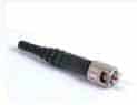
ST connector 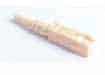
SC connector 
LC connector 
Get more of Elevator World. Sign up for our free e-newsletter.