
Cyrus W. Baldwin was the first to introduce the VT community — at home and abroad — to this concept.
The successful debut of Elisha Otis’ improved safety device in 1854 and its subsequent patent in 1861 established the top of the car or platform as the obvious location for such devices. This remained the dominant paradigm throughout most of the 19th century. However, in 1870, a rival system appeared that challenged this approach. The new system was developed and patented by Cyrus W. Baldwin (1820-1898), the inventor of the water balance elevator.
Baldwin’s 1870 patent concerned a safety device whose design was developed in direct response to the perceived limitations of safeties mounted on the platform’s crossbar:
“As heretofore constructed the safety device or stop of elevator-carriages has been applied to the crosshead … my invention consists in applying the safety device … to the underside of the platform … I have contemplated the application of the principle of my present invention to elevators formerly constructed, in which toothed racks and two bent levers, operated by a semi-elliptic spring … were the means employed for arresting the accidental descent of the carriage. As so constructed, the supporting-rope is at all times connected to the eye-bolt, and, consequently, to the safety device, and thus is liable, by being caught and drawn taut accidentally at any time after the breakage or release thereof, to release the hold of the bolts upon the racks, and start the carriage again upon its illegitimate descent.”[1]
Baldwin was not the first inventor to contrast a design to Otis’ ratchet-and-pawl safety, nor was he the first to comment on its limitations. What separated him from his peers was his decision to place the safety under the platform.
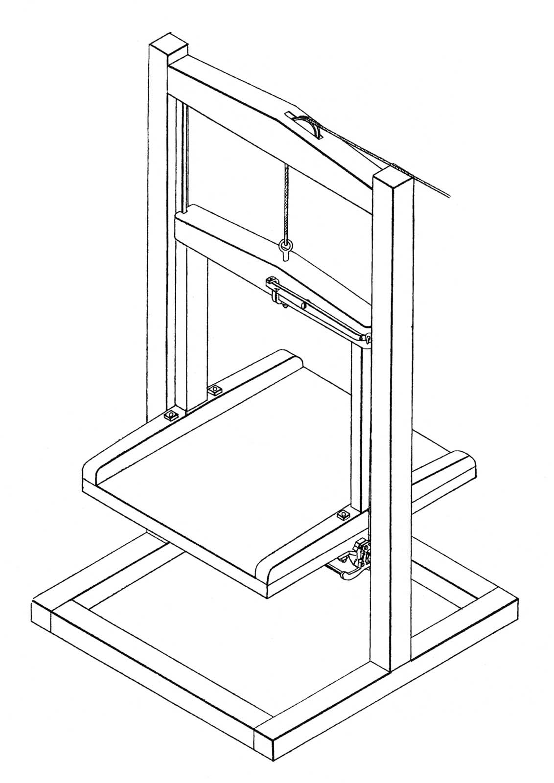
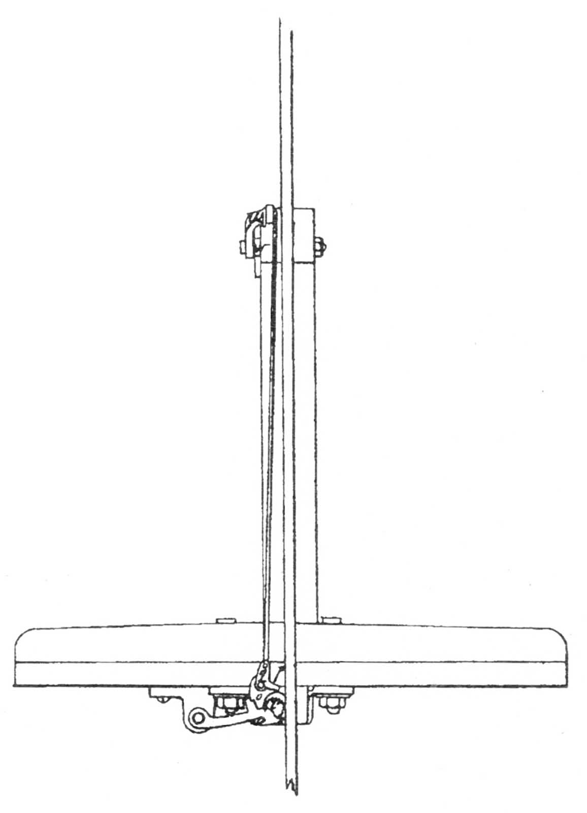
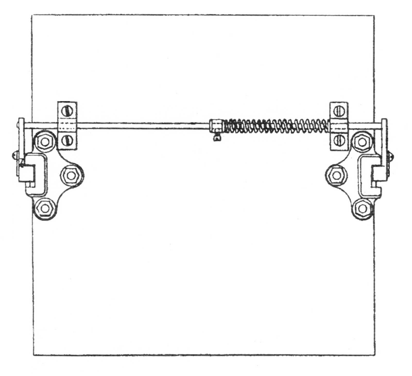
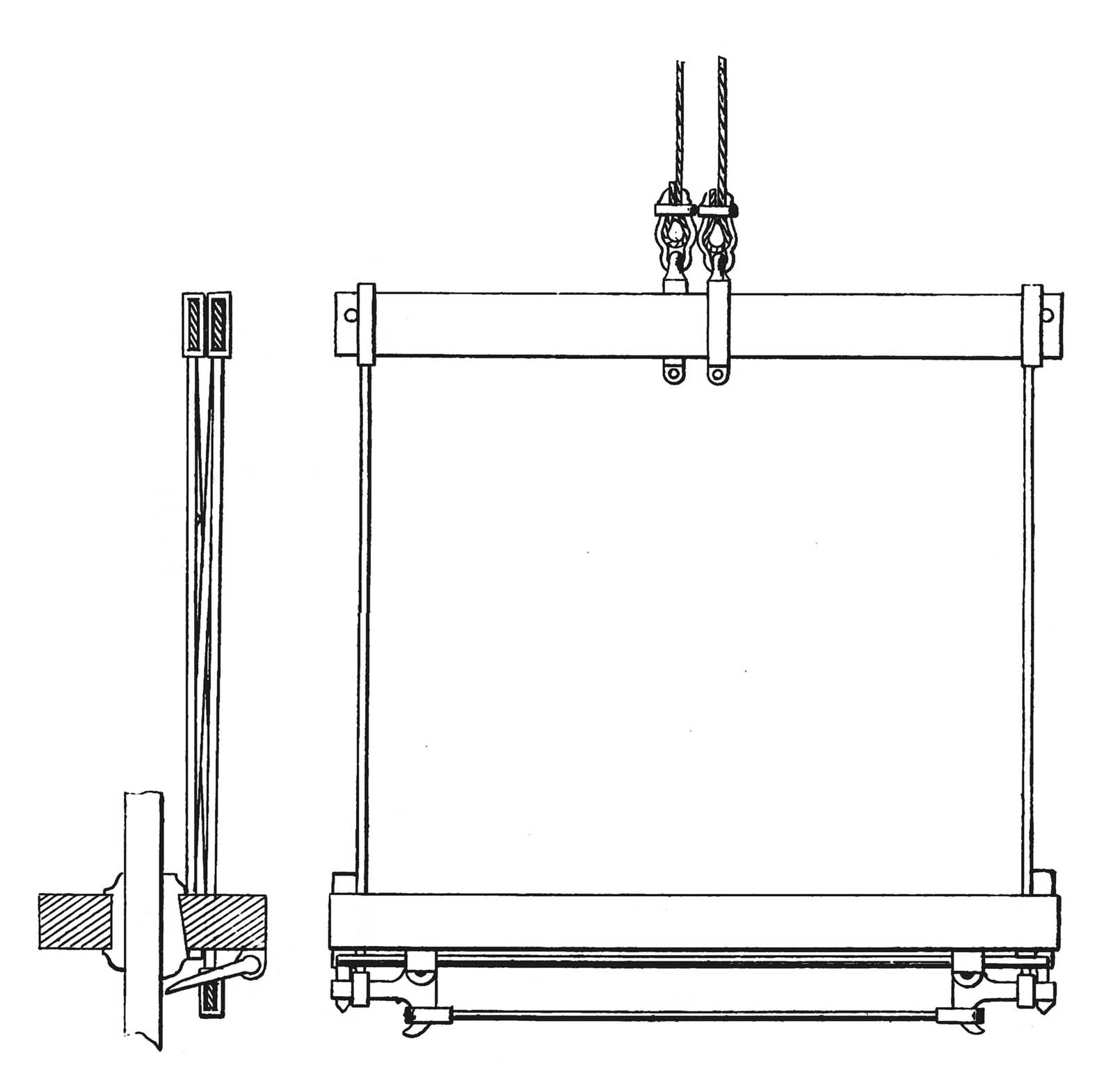
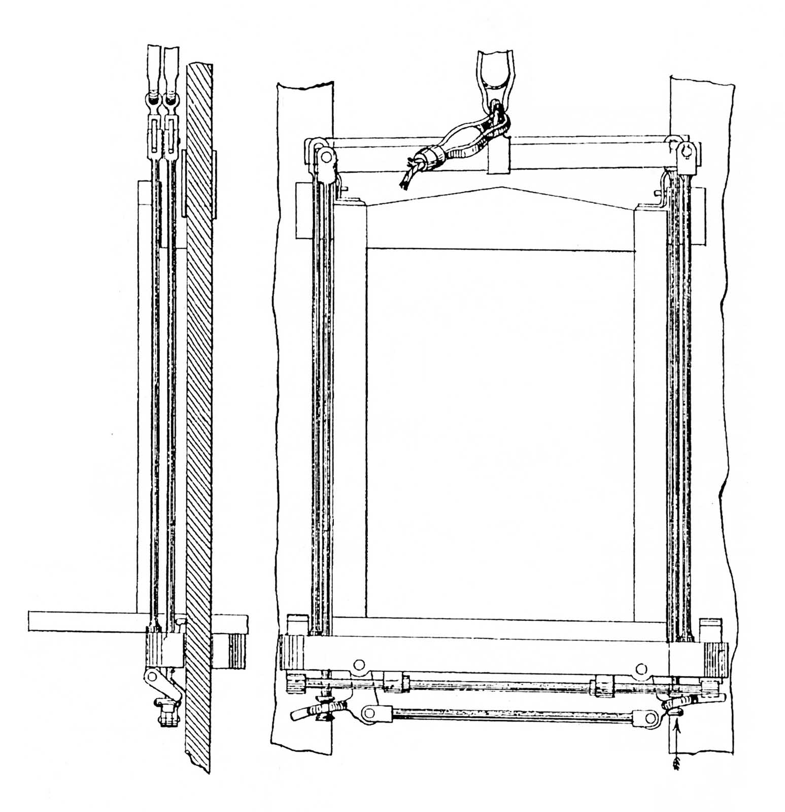
His safety, like Otis’, was activated by the failure of the hoisting rope. The rope was attached to an eyebolt attached to a short vertical rod, equipped with a spring, housed in the crossbar. The rod was connected to a horizontal bar that was in turn attached to a vertical rod that ran down the outside edge of a side post (between the platform and guiderail), which was attached to a “trigger” that activated the safety (Figures 1 and 2). The weight of the car kept the crossbar spring compressed, which held the safety in its “off” position. If the rope failed or became slack, the spring expanded, which pushed the end of the horizontal bar down; this action raised the vertical bar and released the trigger that activated the safety device. Once the trigger was released, even if the rope regained its tension on the spring, the safety remained activated. The device employed two recessed brackets that functioned as guides, and which housed fluted rollers (Figure 3). The rollers were attached to the ends of a rocker shaft, which featured a spring that prevented the shaft from rotating and thus held the rollers away from the guiderails. When the safety trigger was released, the spring rotated the shaft, forcing the fluted rollers into contact with the guiderails, stopping the platform’s descent.
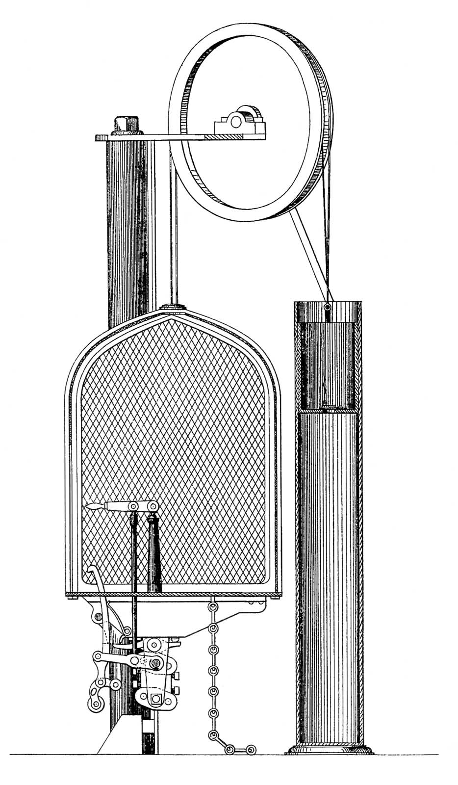
In an 1872 patent, Baldwin proposed applying an under-car safety to a water balance elevator. In this scheme, the hoisting ropes were also attached to the bottom of the platform (Figure 4):
“My present invention consists, first, in suspending and operating an elevator-carriage from the bottom thereof, in lieu of the top as now universally practiced, my purpose in so doing being … to obtain more nearly absolute means of safety against accidental fall of an elevator-carriage, since there are no connections between the platform and top, the sundering of which would precipitate the former to the bottom of the building.”[2]
Baldwin’s “absolute means of safety” was achieved by the application of a complicated safety device:
“My present improvements will be found to consist in a novel mode of attaching the hoisting-ropes or suspensories to the carriage-floor or platform, and the combination therewith of a safety stop-motion or device, which, upon fracture of any one suspensory, sets free the said stop-motion and allows it to arrest the descent of the carriage and prevent accidents; this second portion of these improvements consisting in connecting the suspensories to the upper ends of a series of upright rods, playing in suitable brackets or housings, applied to one or both sides of the platform and provided with springs to depress them under certain conditions, the lower ends of said rods resting upon the inner extremity of a tilting or oscillating lever fulcrumed to the side of the platform and below the brackets or housings above named, the outer or front extremity of the said lever being situated below the inner and free end of an arm or tripper fixed to one end of a horizontal rocker-shaft, which rocks in suitable bearings placed below the carriage-platform, the last element in this safety device being a fluted roller, which, in turn, rests upon the free end of the tripper above named and is deposited in a converging channel, contracted at the top, said channel being a groove or recess created in the housing or bracket above named and in which an upright rail or slide is situated, the arrangement of parts being such that upon fracture of one suspensory, the rod to which it is attached is suddenly lowered by the action of its spring, the descent of the rod, through the agency of the oscillating lever and tripper above named, having the effect of throwing the fluted roller with a quick movement upward into the contracted portion of its channel and between the front wall of the latter and the bar or slide above referred to, the roller being so firmly wedged between the two as to lock them together, and consequently arrest instantly the descent of the carriage.”[2]
A careful reading of this somewhat tortured text reveals that the safety’s operation was, more or less, the same as had been proposed in his 1870 patent.
In 1878, Baldwin patented an under-car safety design that replaced the fluted rollers with “friction blocks or wedges,” which, when forced against the guiderails, stopped the car.[3] While the action of the safety was, once again, controlled by the failure of the hoisting rope, this system, which required the use of two hoisting ropes, employed a redesigned crossbar. Instead of a solid wooden support, the crossbar was composed of two parallel metal plates. Each plate had one end attached to a fixed vertical rod and one end attached to a movable rod that was connected to a trigger on the safety. The plates were arranged in an opposing fashion such that the safety employed two triggers (one located on each side of the platform). Baldwin’s description of this device included the first use of the term “safety plank”:
“My car is shown as resting upon a plank or timber constituting the safety. This plank is represented as having in its ends recesses or notches which embrace the slides, and by which the car is guided and kept in position at the bottom. These recesses or notches are wider than the slides and carry in them wedges or keys, which rest on shoulders near their tops, parallel with and arranged in bearings underneath the plank. I place a shaft or bar, whose ends are provided with projecting fingers, having one or more points which are in close proximity to the slides, and which rest immediately under the ends of the wedges or keys, which project below the lower surface of the plank. Pivoted underneath and near the ends of the safety plank or timber are two bell-crank levers, which are held in proper position by a cross rod running from one to the other, so that a movement of one of the said bell cranks will cause a simultaneous movement of the other. The arms of these bell cranks are kept in a horizontal position by the cross rod, and project underneath the fingers or points, and hold them in position … If the suspensory be broken it releases the cross bar and bell crank. The whole weight of the car being thrown on to the cross bar the arm of the bell crank is pulled violently upward, bringing the points of the fingers in contact with the slides. The further movement of the car downward, owing to their angles, forces them deeply into the said slides, and the keys or wedges resting upon them are forced upward between the slides and the walls of the recesses or notches in the ends of the safety plank or timber locking said safety plank or timber firmly to the slides.”[3]
Baldwin’s intended audience was not, however, his American colleagues. The first people to encounter this new technical term were the members of the British vertical-transportation (VT) industry.
The description was found in a British patent (Baldwin filed the application on July 18, 1878, and the patent was sealed on September 2). The patent presents a slight mystery. It included content derived from two of his American patents: the first concerned a vertical hydraulic elevator engine (the application of which was filed on February 8, 1878) and the second concerned an under-car safety device (the application of which was filed on November 1, 1878).[4] However, the British text and illustrations differed from its American counterparts. The application timeline also reveals that the British patent, with regard to the safety device, preceded its American counterpart by three months. The primary difference between the description of the safety found in the patents was the inclusion of more detailed drawings in the American patent and the surprising exclusion of a critical aspect: The phrase “safety plank” was not included in the American patent (Figures 5 and 6).
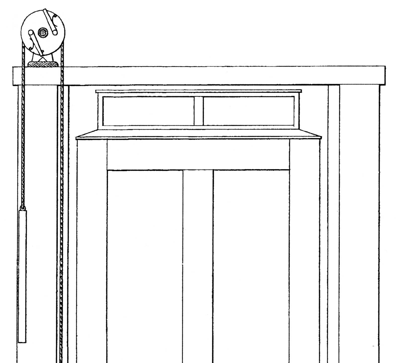
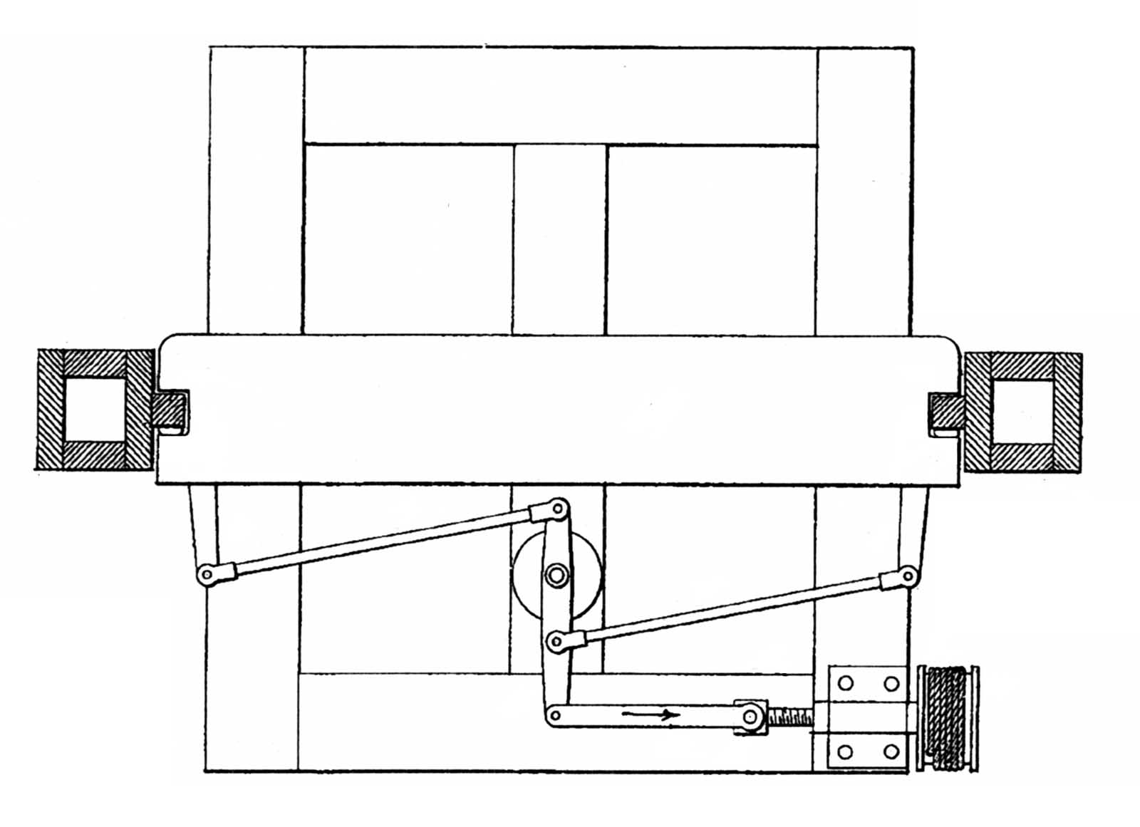
Baldwin waited four years before introducing the American VT industry to the term “safety plank.” While the reasons behind this delay remain unknown (as do the reasons behind its British debut), the wait was, perhaps, worthwhile. In his 1882 patent, Baldwin revealed a new version of his safety that eliminated the reliance on the hoisting rope for its operation. He connected the safety to a secondary rope that used a counterweight to sustain the required tension, and which passed over a combination sheave and governor at the top of the shaft (Figure 7). If the car exceeded a preset speed, the governor grasped the rope, which activated the safety (Figure 8):
“The cage slides between the usual guides, which extend into recesses or grooves in the guide-plates on the safety-plank; levers are pivoted to said plates and provided with loosely-attached clamp-blocks, which, by the outward movement of the levers, may be brought against the guides as brakes to reduce the speed of the cage or to pinch the plates tightly against the guides and arrest the cage … The clamps may be applied … (by) a revolving governor … any undue increase of speed shall effect the clamping or retarding of a rope, which, when arrested, causes the brakes to be applied … (via) a screw-shaft, turning in a box-on the bottom of the cage, and carrying a traveling nut, pivoted to a link, connected to a lever, to which are also connected rods attached to the ends of the brake-levers. At the end of the shaft is a drum, round which the rope is wound. When the travel of the rope is arrested the drum and its shaft are turned, the nut is carried outward in the direction of the arrow, and the brakes not only applied with great force, but held fixedly in the position to which they are set.” [5]
While Baldwin’s decision to make the safety’s action independent from the hoisting rope and dependent on the speed of the car paralleled the efforts of other designers, his insistence on its location beneath the car set him apart from the majority of VT engineers. Although he was joined by a small number of like-minded inventors in the pursuit of an under-car safety device, he was the only one who consistently pursued the development of this safety type throughout the 1870s. And, he was the first to introduce the VT community — at home and abroad — to the concept of the “safety plank.”
References
[1] Cyrus W. Baldwin, Improvement in Elevators, U.S. Patent No. 109,169 (November 15, 1870).
[2] Cyrus W. Baldwin, Improvement in Elevators, U.S. Patent No. 123,761 (February 20, 1872).
[3] Cyrus W. Baldwin, Safety Hydraulic Lifts, British Patent No. 2,863 (September 2, 1878).
[4] Cyrus W. Baldwin, Improvement in Hydraulic Elevators, U.S. Patent No. 201,980 (April 2, 1878) and Improvement in Elevators, U.S. Patent No. 216,013 (June 3, 1879).[5] Cyrus W. Baldwin, Safety Apparatus for Elevators, U.S. Patent No. 258,691 (May 30, 1882).

Get more of Elevator World. Sign up for our free e-newsletter.
![]()


![]()