The Royal Institution’s Micro Leveling Elevator
Oct 1, 2018

A rare Otis Construction Handbook sheds light on the story of a unique, newly restored elevator in London’s Faraday Museum.
London is filled with architectural, cultural, historical and technological treasures. One such treasure is in the Mayfair neighborhood at 21 Albemarle Street. There, visitors will find the Royal Institution of Great Britain, more commonly known as the Royal Institution (RI). Founded on March 7, 1799, it was described by its creators as an:
“Institution for diffusing the knowledge, and facilitating the general introduction, of useful mechanical inventions and improvements; and for teaching, by courses of philosophical lectures and experiments, the application of science to the common purposes of life.”[1]
Over its history, the RI has supported and housed the work of a remarkable group of scientists, including Humphry Davy, Michael Faraday, John Tyndall, James Dewar, Lord Rayleigh, William Henry Bragg, Henry Dale, Eric Rideal, William Lawrence Bragg and George Porter. Today, the RI continues its mission of supporting research into and educating the public on the “application of science to the common purposes of life.” Its activities include a variety of public lectures and educational events held throughout the year. The RI also houses the Faraday Museum, which contains a collection of scientific instruments dating from 1799, as well as Faraday’s “magnetic laboratory displayed as it was in the 1850s.”[1]
An added attraction here for elevator- industry members is a recently restored 1929 Waygood-Otis Micro Leveling Elevator (Figures 1 and 2). The restoration effort was led by John Nichols and Derek Smith, both of whom are retired from Otis. Their work has been well chronicled in a series of illustrated articles published in Elevation (available as Online Extras during October at www.elevatorworld.com). The articles highlight the challenges of the renovation project, as well as the innovative aspects of the almost-90- year-old elevator, which was one of the first machine types designed to automatically stop level with floor landings. In 1931, Frederick Hymans described the primary components of micro-leveling elevators as follows:
“They comprise a main machine for the hoisting operations between floors and an auxiliary machine to which the load is transferred shortly before the stop, and which brings the car to the landing at slow speed. It is the slow speed of the auxiliary machine and its control by a leveling switch that enable the micro-drive machine to make its exceedingly accurate stop. The main machine may be either worm geared or gearless; but, the auxiliary machine, in order to obtain the required slow speed, is always a worm-gear machine In the micro-machine, then, the purpose of the main
machine is to hoist the load at full speed and to stop the car within the leveling zone of the desired landing. At this point, the leveling switch takes control and operates the auxiliary machine to bring the car at slow speed to a stop level with the landing.”[2]
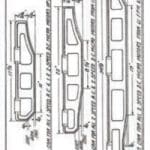
Hymans also provided a detailed plan drawing that depicts a machine similar in design to the RI elevator (Figure 3). In the late 1920s, this system represented the state of the art in electric elevator design. Its restoration allows it to take its place alongside other museum exhibits, with the added advantage of its operational character.
Of course, the Faraday Museum is more than a visual collection of machines and instruments. The exhibits emphasize the intellectual concepts that informed the creation and operation of the museum’s collection. Thus, if the museum were to have an exhibit on the history of its elevator, it would probably include pictures of the 1929 installation, pictures of the restored machine, original tools used to install and maintain the machinery, and — to address the intellectual and engineering basis for the system’s design and operation — two small, black, leatherbound binders (Figure 4).
The introduction of micro-leveling elevators in the early 1920s coincided with the publication of the Otis Construction Handbook, which was designed to be used by “servicemen.” The handbook was necessary because of the increasing complexity of new systems and the need for greater precision in machine installation and maintenance. The handbook was designed for durability (materials were placed in black, leatherbound three-ring binders) and to fit in toolboxes (each binder was approximately 6.5 X 4.5 in. in size). The three-ring-binder format also allowed for easy updating. The handbook’s contents were organized into 22 “groups,” which included sections on general information and material that concerned specific installation types. Examples of the various groups include:
- “I. Rails, rail fasteners, beams, foundations, gratings, etc.”
- “II. Deflector sheaves, overhead sheaves, sheave boxes, etc.”
- “III. Machines, alignment gauges, gears, thrust bearings, driving sheaves, motors, generators, compensators, commutators, armatures, brushes, brakes, brake magnets, etc.”
- “IV. Main controllers, micro controllers, floor controllers, floor switches, overload relays, reverse phase relays, transformers, etc.”
- “V. Car switches, push buttons, throwover switches, leveling switches, limit switches, wire, conduit, electrical fittings, etc.”
- “VI. Car safeties, governors, buffers, releasing carriers, etc.”
- “VII. Ropes, counterweights, compensating ropes and chains, etc.”
- “VIII. Door locks, retiring cams, door and gate contacts, lubricants, etc.”
Each group was further subdivided into discrete subjects, such as “V-25: Installation and adjustment of leveling switches for micro leveling elevators.” Each data sheet featured a title block at the bottom of the page that gave the publication date, content group or subsection designation, and page number (Figure 5).
The Otis Construction Handbook was first published in January 1924. The dynamic quality of the resource is evident in the fact that Otis issued 25 updates between January 1924 and July 1931. The need for continual updates speaks to the pace of development and refinement of Otis’ elevator systems, particularly its micro- leveling machines. The latter is apparent when comparing photographs published between 1921 and 1939 (Figure 6). The handbook’s contents reveal the complex nature of these machines, illustrated by the installation instructions for a single-wrap geared-traction micro machine:
“First — Always insert 1/4” packing plates under the main bed. Never set the main machine on the beams or concrete floor without packing as it has been found that without said packing plates under the main machine the micro machine cannot be properly aligned.
“Second — Both bedplates must be carefully leveled. This is very important as the factory bolts the two bedplates together before planing, and the two beds are then planed as one unit.“Third — Check the distance from the top of the spot pieces for the main motor to the top of the spot pieces for the small brake on
the micro machine. These distances should be as follows for the various sizes of machines:
| “#2 A.C. & D.C | Distance = 5-3/8” |
| 3 A.C. | Distance = 8-1/8” |
| 3 D.C | Distance = 7” |
| 4 A.C. & D.C. | Distance = 7” |
| 5 A.C. & D.C. | Distance = 8-17/32” |
| 7 A.C. & D.C. | Distance = 5-23/32” |
“Fourth — After setting main motor in place on bedplate align main motor and worm shaft.
“Fifth — Align revolving micro brake shoe frame and pulley by means of two set screws in the tapped holes provided in the brake frame by the factory.
“Sixth — The micro gear case, motor, brake and bedplate are always shipped in one unit, and in most cases if carefully set and leveled as described above should not require realignment, but the alignment of the micro motor and worn shaft must always be checked after all of the above steps have been followed and, if necessary, realign.”[3]
A similar level of detail was provided for all aspects of machine installation and operation, with most groups featuring drawings of key components. Examples of these drawings include those provided for the car leveling switch and leveling-switch contacts (Figure 7). In addition to machine installation and component operation instructions, the handbook also included a detailed description of how to adjust a fully assembled system:
“In adjusting automatic elevators equipped with the micro drive leveling device, great care must be exercised in setting the main machine floor controller, micro-leveling cams in the hatchway, and the micro-leveling switch on the car frame.
“After the normal slide of the car with balanced load has been determined by test, set the machine floor controller so that car makes a level stop without the functioning of the micro-leveling machine. Obviously, then, with full load descending, the car will stop below the floor, and, with no load descending, the car will stop above the floor. This setting of the main floor controller provides for the shortest possible period operation of the micro motor and with ordinary loads the least use of the motor.
“The micro-leveling switch and the micro-leveling hatchway cams should then be located so that the micro-leveling switch arm rollers are on the center of the steep incline of both micro-leveling hatchway cams when the car platform is in exact register with the floor. In this position, the micro switch contacts will be opened and the circuit of the micro motor will be interrupted. With this setting, should the car platform move out of exact register with the floor, due to stretch of ropes or for any other reason, the up/down micro-switch arm roller will immediately be deflected, closing either the up or down contact in the switch, which connects in the micro motor and brings the platform to an exact register with the floor.”[4]
The clarity of this description is such that it is easy to imagine Waygood-Otis servicemen following these instructions and the resulting “magic” of the elevator’s automatic leveling.
It should be noted that the presence of an Otis Construction Handbook onsite at the RI in 1929 cannot be confirmed. It is, however, a reasonable assumption, based on Otis’ overall approach to marketing and technical support during this period. In fact, the presence of these handbooks outside the world of Otis is rare. This fact is explained by the explicit instructions found on the handbook’s inside cover:
“The person to whom this Handbook is issued is held personally responsible for its proper care and safekeeping. It must not be loaned or transferred without proper authority, and when a position is vacated, the holder must return the Handbook to the Company.”
Fortunately, a former Otis employee clearly disregarded this mandate (the consequences for this action remain unknown), and two handbooks (one covering “Groups G to IV, Inclusive,” and one covering “Groups V and Up”) were discovered and now reside in my collection of historic materials. (Note: excerpts from the handbook are available as Online Extras). While, regrettably, the handbooks’ contents are incomplete, they contain enough material to shed significant light on Otis elevator installation and operation in the 1920s. They also effectively illustrate critical aspects of the RI’s 1929 micro-leveling elevator, a unique unit in an equally unique setting.
Acknowledgements
Your author thanks Charlotte New, curator of collections at the RI, for inviting me to visit the RI and see this elevator in September 2017. He would also like to thank John Nichols and Derek Smith, who graciously shared “their” elevator and wealth of knowledge.
Their dedication to this project and its successful conclusion is a remarkable story.
-

- Figure 1: 1929 Waygood-Otis Micro Leveling Elevator Machine, RI, London
-

- Figure 2: 1929 Waygood-Otis Micro Leveling Elevator Shaft, RI, London
-

- Figure 3: Micro Leveling Elevator, circa 1930: Parts: (a) motor, (b) worm gear, (c) driving sheave, (d) auxiliary motor, (e) brake, (f) worm gear, (g) revolving brake and coupling
-

- Figure 4: Otis Construction Handbook, Otis (1924-1931)
-
- Figure 5: Typical data sheet, Otis Construction Handbook (1924-1931
-
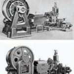
- Figure 6: Micro Leveling Elevator Machines: (bottom to top) 1921, 1923, 1925, 1939.
-
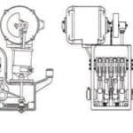
- Figure 7: Car leveling switch and leveling switch contacts; drawings derived from datasheets published in the Otis Construction Handbook (1931).
References
[1] Royal Institution of Great Britain (www.rigb.org).
[2] Frederick Hymans, Electric Traction Elevators, International Textbook Co. (1931).
[3] Otis Construction Handbook, “Group III-1. Handling, Setting and Aligning Machines: Single Wrap Geared Traction Micro Machines” (May 1, 1929).
[4] Otis Construction Handbook, “Group V-25. Installation and Adjustment of Leveling Switches for Micro Leveling Elevators: Adjustment of Leveling Switch for Micro Drive Automatic Button Control Elevators” ( January 1, 1924).

Get more of Elevator World. Sign up for our free e-newsletter.


