The Two Modes of Failure of Escalator Braking Systems
Jun 3, 2022

This paper was first presented virtually at the 12th Lift & Escalator Technologies Symposium in September 2021 and printed at the symposium website at liftsymposium
Keywords: Escalator braking systems, runaway condition, escalator kinematics, passenger falls, intelligent braking systems deceleration, jerk
Abstract
The braking system in an escalator is the most critical safety component. Failure of the escalator braking system can lead to passenger injury and even fatalities. Escalator braking systems can fail in two modes: In the first mode of failure, the braking system fails to arrest the descending load and slow it down when it is not correctly adjusted or completely out of adjustment. This leads to a runaway situation.
The second mode of failure is when the escalator braking system is so tightly adjusted that it leads to a severe stop of the escalator and consequential passenger falls. Passenger falls on escalators are one of the major causes of accidents including cuts, bruises, finger entrapment and, in certain cases, crushing leading to suffocation. The paper provides an overview of these two types of failures, their causes and possible solutions. One of the technical solutions previewed is the use of intelligent escalator braking systems to control the deceleration of a stopping escalator. Two technologies exist for controlling escalator braking systems: electrical and hydraulic.
1. Introduction
The braking system in an escalator is the most critical component. Failure of the braking system on an escalator can lead to passenger injuries or fatalities.
This paper attempts to review the failure of the braking system that leads to passenger injuries. There are two modes of failure for escalator braking systems. The first mode of failure of the braking system is when it fails to slowdown and stop the loaded escalator. This leads to a dangerous increase in speed and the consequential passenger injuries caused by the formation of a “human pile” at the lower landing of the escalator. The second mode of failure of the escalator braking system is when the braking system applies too harshly when it is lightly loaded, causing passengers to lose balance and fall, with consequential injuries in the form of cuts, bruises and even finger entrapments.
It could be argued that these two types of failures are not failures in the classical sense of the work (e.g., a classical failure is when a component is damaged, or a sensor fails to send a signal). While this is true, these two failures are basically forms of maladjustment leading to the inability of the braking system to perform its function. Hence, they have been classified as failures in this paper.
It is worth noting that the first mode of failure is easily reversible if detected in good time. It is also worth noting that there are other failure modes in the escalator that are irreversible. A better understanding of the contents of this paper can be gained by understanding the status of safety regulations for major escalators in the world.
This paper reviews the research and practical work carried out to date in all the areas above. The paper provides some necessary background information about escalator braking in terms of the passenger accident causation model (Section 2), the anatomy of an escalator stop (Section 3), the standard requirements regarding escalator braking system performance (Section 4) and the requirement for weight testing in public service escalators (Section 5). The problem of escalator runaway accidents is reviewed in Section 6, including suggested new methodology for testing the escalator braking system without the use of weight to avoid this failure mode. Section 7 examines the experimental work done in finding a relationship between the kinematics and mechanics of the stopping escalator and the risk of passengers falls. The work done in this area provides a recommended value for the maximum value of deceleration that should not be exceeded during an escalator stop. Section 8 reviews two types of intelligent braking systems that are used to prevent the deceleration of the stopping escalator exceeding these recommended values: hydraulic braking systems and electrical braking systems. Conclusions are drawn in Section 9.
2. The Escalator Passenger Accident Causation Model
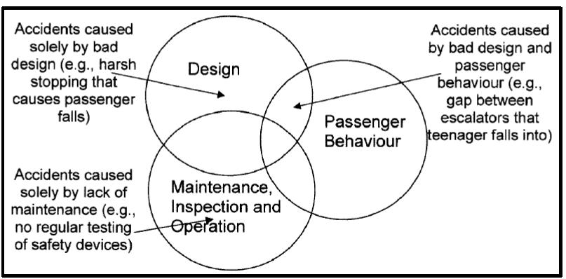
It is useful at this stage to discuss the passenger causation model in escalators. Previous research has identified three categories that lead to passenger accidents on escalators:[1]
Design: During the design phase of the escalator braking system, the risk of brake failure can be reduced or eliminated.
Inspection and maintenance: Inspection is critical in identifying problems in the braking system early and addressing them via maintenance.
Passenger behaviour: Passenger awareness is important in avoiding accidents. Good awareness could avoid the risk of passenger falls (e.g., holding onto the handrail and facing the direction of travel).
This model provides a guidance framework for the prevention of passenger accidents (Figure 1). By analysing the three categories above (or a combination thereof), it is possible to identify the root causes of an accident and prevent it. More on passenger accidents on escalators can be found in References [2] and [3].
3. Anatomy of an Escalator Stop Under the Influence of the Braking System
Another useful tool that can be essential in understanding brake operation, and thus brake failure, is the speed-time profile of the escalator step-band during a stop. The speed-time profile is a plot of the speed of the step-band of the escalator against time.
Figure 2 shows the speed-time profiles for a public service escalator. The braking systems comprise two parts: An operational brake and an auxiliary brake (using EN 115-1:2008 terminology). Both brakes are hydraulically lifted and spring-applied (for obvious safety reasons).
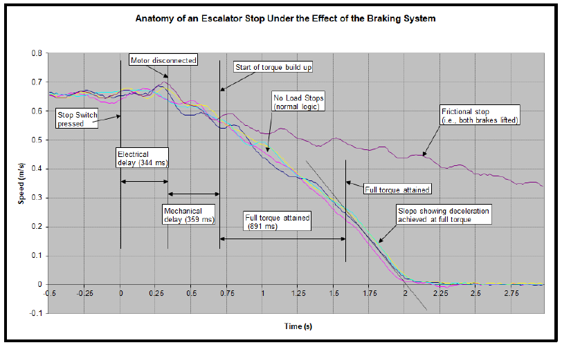
As can be seen, the stopping time (from the time that the stop-switch is pressed until the escalator comes to a complete standstill) is around 2 s. This stopping time includes the electrical delay (around 350 ms), the mechanical delay (around 360 ms), the brake torque build-up (around 890 ms) and the final stopping time under full brake torque (around 400 ms).
The figure also shows the comparison with a frictional stop (where the escalator stops under the effect of friction only, without any braking torque). This is useful for indicating the mechanical status of the step-band.
It is believed that the maximum value of the deceleration during an escalator stop is inversely proportional to the risk of passenger falls.
4. Brake Performance Requirements
The brake performance requirements as set out in the European Standard EN 115 stipulate only maximum and minimum stopping distance. The maximum stopping distance relates to the fully loaded escalator running in the down direction. The minimum stopping distance relates to empty stopping escalator (see Table 1).
The rationale for this is that the escalator should not stop too abruptly when empty, so that it does not cause passenger falls when passengers are travelling on it. When fully loaded, it should be able to stop within a reasonable distance to protect passengers from a runaway situation.
| Rated speed | Stopping distance |
| 0.50 m/s | min. 0.20 m; max. 1.00 m |
| 0.65 m/s | min. 0.30 m; max. 1.30 m |
| 0.75 m/s | min. 0.35 m; max. 1.50 m |
The American Standard (ASME A17.1-2010/CSA B44-10) specifies the maximum value of deceleration of the escalator as 0.91 m/s2.
The stopping distance on its own is a poor indicator of brake performance. Based on several pieces of research, there is strong evidence to suggest that the maximum value of deceleration is the best indicator of passenger stopping comfort and the risk of passenger falls.[4] It is believed that the maximum value of the deceleration during an escalator stop is inversely proportional to the risk of passenger falls. EN 115 has been re-drafted to specify an additional maximum deceleration requirement of 1 m/s2, in addition to the stopping distances.
5. Weight Testing Requirements on Public Service Escalators
Prior to discussing the mode of failure where the braking system fails to slow down the loaded escalator and bring it to a standstill, it is useful to look at the weight testing that is carried out on public service escalators to mitigate the risk of such a failure.
The function or the braking system on the escalator is to ensure that the fully loaded escalator is brought safely to a standstill when required to do so following the tripping of a safety device or the activation of the passenger emergency stop switch. Recent developments have introduced the use of electrical braking systems to complement the mechanical braking systems.[5]
It is generally a requirement that full-load weight testing be carried out for new, refurbished and partially refurbished escalators to prove that the braking system is capable of (and has been set up to) arresting the fully loaded escalator running in the down direction at rated speed and bringing it to a standstill within the distances stipulated by EN 115-1:2008.
Weight testing is a very lengthy and costly process. It is carried out when an escalator has been replaced or refurbished or where the braking system has been altered. This is especially critical on public service escalators. Public service escalators are subjected to high levels of passenger traffic, which makes the safety of the brakes even more critical.
A value of 150 kg per step is generally assumed in order to calculate the motor or inverter size for public service escalators. The 150 kg is equivalent to two passengers per step weighing 75 kg each and is over and above the requirement of EN 115-1: 2008.
Much research has been carried out on the energy drawn by escalators[6] that have shown that the power drawn by an escalator in kilowatts can be calculated as follows (and is central to the weightless weight testing methodology that is discussed later in this section: by finding the no-load power drawn by the escalator, it then becomes possible to find the frictional torque in the escalator):
PNL = 0.47 ⋅ r + 1.74
Where:
PNL is the power drawn by the escalator at rated speed and no load in kilowatt
r is the escalator rise in m
A previous paper[7] presented a measurement-based-model that allows the prediction of the stopping distance of an escalator under loaded conditions to obviate the need for the full-load weight testing. Such a model will enhance the level of safety in escalators and allow a more scientific approach to the subject of weight testing and proofing of the brakes.
If the relationship between the steady-state speed, deceleration and stopping distance is clarified under the regulatory standards, physical information that leads to the status of accident countermeasures can be obtained.
6. Runaway Conditions on Escalators
Runaway situations are one main source of serious passenger injuries on escalators. A runaway situation takes place when a heavily loaded escalator accelerates downward, exceeding its rated speed and causing a passenger pile at the lower landing. An example of a runaway situation was the accident at the CN Tower in Toronto that took place in 1988. The following is an excerpt from the news item in the press (ELEVATOR WORLD, December 1988):
“Nine children were taken to the hospital after being in a human pile-up on an escalator at the base of Toronto’s CN Tower, but were quickly released. Staff-Sergeant Doug Ecklund of the Metro Police said witnesses reported that the escalator seemed to accelerate before halting after the emergency stop button was pushed. He said an adult pushed the button after becoming concerned about congestion at the base of the escalator.”
Runaway situations take place when the braking system of the escalator is not properly adjusted and cannot bring the loaded escalator to rest. When the escalator stops unloaded or lightly loaded, the friction in the escalator is sufficient to stop it. However, when the escalator is heavily loaded with passengers (as is the case during rush hours or following major events, such as football matches or concerts), the braking system is unable to stop the loaded escalator when the stop button is pressed. Passengers are reported as saying: “I pressed the stop switch a number of times, but the escalator did not stop!” Tests carried out after the accident do not reveal the problem, as the escalator is stopped with no load on it, and friction is sufficient to bring it to rest.
What happens during a runaway situation is outlined here. A down-moving heavily loaded escalator is given a command to stop (either by someone pressing the stop switch or by a spurious safety device trip). The motor is then disconnected from the source of supply by the tripping of the main contactors. By taking the power away from the motor, the escalator is left to move freely under gravity. As the braking system is ineffective, the escalator and its load start accelerating downward. Attempts by passengers to stop it by pressing the stop switch are futile, as the escalator is already “electrically” stopped, and is, in fact, mechanically under gravity. The escalator accelerates to dangerously high speeds (speeds as high as 2 m/s have been reported). Passengers get to the lower landing falling on each other and forming a “human pile.” Once a significant number of passengers have been “thrown” off the escalator, the escalator starts slowing down until it stops under friction.
In cases where the heavily loaded escalator is moving upward, the escalator slows to a standstill and then reverses direction and accelerates downward in the same sequence of events discussed above for the case of the downward moving escalator.
In certain cases, the cause of the runaway is not a defective braking system, but a mechanical shearing of the top shaft of the escalator. The sequence of events, however, is similar.
If the problem is not detected by operational staff, what happens sometimes is that the escalator is left in service (in a stationary condition) following the accident. New passengers arriving find the escalator stationary and think that it is in service as a fixed staircase. Once sufficient passengers have boarded the stationary, defective escalator, it starts moving downward under gravity, repeating the sequence of events above.
The following are examples of runaway incidents:
- Toronto CN Tower, December 1988 (down)
- MARTA (Metropolitan Atlanta Rapid Transit Authority), Atlanta, Georgia, U.S., Escalators locked off to prevent free-wheeling during crowded conditions
- London Underground, London, U.K., Oxford Circus Station, Escalator number 4, August 1999 (sheared top shaft)
- 18 January 2000, Nashville International Airport, U.S.
- Newcastle, England, U.K., Metro escalator, 1 May 2001 (up)
- Newcastle, Metro escalator, 9 February 2002 (down).
- London Underground, London, U.K., Waterloo Station, 2002.
- Anaheim, California, baseball fans, 7 May 2002, 15 passengers with minor injuries (down)
- Coors Field Stadium, Denver, Colorado, U.S., July 2003, 20 injured.
- Raffles City Shopping Centre, Singapore, May 2003, (up), 1 person hospitalised
- Escalator reversed direction, Xinzhuang Station, Shanghai, China, number one subway line, 38 people injured (up)
A recent paper by David Cooper more comprehensively covers this type of failure.[8] The current status of risk control for escalators can be grasped by describing the diffusion rate of safety measures after the revision of EN 115-1:2008.
7. Research Into the Effect of the Kinematics of a Stop on Passenger Falls
The other mode of failure is the escalator stopping harshly when lightly loaded and causing passengers to fall. Passenger falls on escalators can be caused by escalator stops. It has been shown that 2.5% of escalator unplanned stops can lead to passenger falls. Passenger falls on escalators can lead to a range of injuries, starting from cuts and bruises upon impacting the steps, finger entrapment between the steps and the skirts and as severe as crushing at the lower landing due to other passengers falling on each other with the risk of suffocation.[9]
Three studies have been carried out into the relationship between the risk of passenger falls on a stopping escalator and the kinematics of the stop. The methodology is based on asking volunteers to assess the quality of the stop either in words [4],[10] or on a numeric scale from 1 to 10.[11]
The work in References [4] and [11] concludes that a value of 1 m·s-2 for the value of acceleration during an escalator stop seems to be a reasonable limit to impose on the maximum value of acceleration during a stop.
This method is based on the use of human subjects who would ride the escalators during the stop and provide a subjective assessment of the quality of the stop and their assessment of the risk of falling. An example of this empirical approach can be found in Reference [10], where experimental tests on subjects were used to find their perception threshold of movement in relation to age and other factors.
The research in this area can be summarised as follows:
- General research on the risk of passenger falls[12],[13],[14]
- The qualitative relationship between passenger falls and the kinematics of a stop[11],[4],[10]
- The quantitative relationship between passenger falls and the kinematics of a stop using analytical models[15]
- The outcome of all these pieces of research (both quantitative and qualitative) shows that:
- The most important factor in causing passenger falls during an escalator stop is the maximum value of the deceleration.
- Placing an upper limit on the value of deceleration of a stopping escalator of 1 m/s2 would ensure that most passenger falls caused by the escalator stop are eliminated.
This value would be the recommended target design and testing value that would be used as a testing criterion for the acceptability or otherwise the performance of the escalator braking system. Such a criterion would eliminate the risk of passenger falls caused by the escalator’s unplanned stoppage. The next section discusses how the use of intelligent braking systems is applied to achieve this requirement.
8. Intelligent Braking Systems
As discussed in the earlier sections, a limit must be placed on the maximum value of the acceleration of a stopping escalator to ensure that passenger falls are avoided when a lightly loaded escalator stops (especially in response to a safety device tripping or a manually operated stop switch).
The maximum allowable value of the deceleration of the stopping escalator can be used as the control variable in the intelligent braking system. An intelligent braking system is a system that controls the stopping speed profile of the escalator to achieve the required stopping distance or speed. A block diagram of a generic intelligent braking system is shown in Figure 3 below.
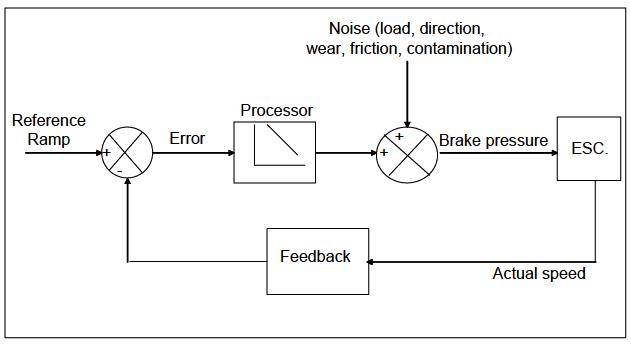
It is now possible with the use of modern escalator braking systems (electrically or hydraulically based intelligent braking system) to continuously monitor the value of speed and acceleration of the escalator in real time and adjust the electrical braking effort in order to avoid the deceleration exceeding the target value. This is outlined in detail in References [5] and [16].
Hydraulically based systems: Hydraulically based systems require that one of the conventional brakes be hydraulically lifted. Hydraulic systems control the hydraulic pressure lifting the brake pads off the disk. This can be done by either the use of a linearly proportional valve or using on/off modulation by varying the duty ratio (i.e., on/off ratio). Hydraulically based intelligent braking systems are discussed in more detail in Reference [16].
Electrically based systems: Modern escalator control systems are equipped with variable speed drives that are used for starting the escalator and running it at different speeds during the day. This drive can also be used to implement the intelligent braking function. Electrically based systems employ the variable speed drive (usually a VF drive) to bring the escalator to a standstill and then apply the mechanical brakes as holding devices. In this case, the mechanical brakes that are used for conventional braking become merely parking brakes applied once the escalator has come to a standstill. The inverter used on this system does not employ closed loop feedback, and it relies on the fact that the motor will follow the speed that is set by the frequency sent by the drive.
An example of the performance of an electrically based intelligent braking system is shown in Figure 4. It is clear from the figure how the braking system achieves the same deceleration regardless of the load on the escalator.[5]
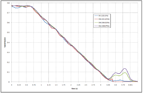
Generally, the electrically based intelligent braking system is now becoming more widely used, compared to the hydraulically based systems. A comparison is shown below:
- The electrical braking system is generally found to be faster in responding to changes in the speed of the escalator, and thus achieves a much closer control on the speed profile.
- In general, the cost of the electrical braking system is lower than the hydraulically braking system, as many of the modern escalators already contain a variable speed drive. In order to implement a hydraulic based intelligent braking system, a special controller is needed as well as a pulse width modulation (PWM) feature, in order to control the operational brake valve.
- The implementation of the electrical braking system contravened older version of the EN 115, but this has now been addressed in the latest revision of EN 115-1:2008.
9. Conclusions
There are two modes of failure of escalator braking systems. The first mode of failure is when the escalator braking system is badly adjusted or worn so that it fails to slow down and stop a fully loaded escalator. This can lead to serious passenger injuries (e.g., suffocation) where the downward speed of the escalator significantly exceeds the rated speed of the escalator. This risk of failure is mainly prevented by regular inspection and maintenance. To avoid the need for weight testing on public service escalators, modern modelling techniques can be used to predict the performance of a fully loaded escalator from deceleration measurements on unloaded escalators.
The second mode of failure is when the braking system causes a harsh stop for the lightly loaded escalator, such that it causes passenger falls. Passenger falls can cause a number of injuries, such as cuts, bruises and even finger entrapments between the step side and the skirting.
It is worth noting that the first mode of failure is easily reversible if detected in good time. It is also worth noting that there are other failure modes in the escalator that are irreversible.
Runaway situations are one main source of serious passenger injuries on escalators.
Research has been carried out into the relationship between risk of passenger falls and the kinematics of the stop. It has been found that there is strong correlation between the deceleration of the stopping escalator and the risk of passenger falls. Kinematic modelling has also found that a restriction of 1 m/s2 must be placed on the value of the deceleration of a stopping escalator to prevent passenger falls on a stopping escalator. This value of deceleration can be used in intelligent braking systems.
Intelligent braking systems can be used on escalators to control the stopping distance and speed of an escalator, regardless of the fluctuations in the load on the escalator and the direction of travel. Two types of such systems can be used: electrically based and hydraulically based. The electrically based system uses the variable speed drive that is part of the electrical control system of the escalator. The hydraulically based system employs an operational brake hydraulic system with a pulse width modulated valve. The electrically based system has been used with good results and shows accurate control of the stopping speed profile regardless of the load.
References
[1] Al-Sharif L. Escalator Stopping, Braking and Passenger Falls. Lift Report, 1996. November/December 1996.
[2] Ferrario M and Hubbard A. Investigation into the Causes of Passenger Accidents on Escalators: Management Report. Human Reliability Associates, reference R93/06, May 1993.
[3] Ferrario M and Hubbard A. Investigation into the Causes of Passenger Accidents on Escalators: Technical Report 3: Behavioural Analysis. Human Reliability Associates, reference R93/06, May 1993.
[4] Stein W et al. Brakes for Escalators & Moving Walks. Lift Report 2003; 29(1).
[5] Al-Sharif L, Seaborne K, Austin D. Electrical based intelligent escalator braking systems. Proceedings of Elevcon 2010, the 18th International Congress on Vertical Transportation Technologies, Lucerne, Switzerland, 2 to 4 June 2010.
[6] Al-Sharif L. Experimental Investigation into the Effect of Mechanical Design of an Escalator and Passenger Loading on its Energy Consumption. The World Congress on Engineering, London, U.K. 2008; 2: 1542-1547.
[7] Al-Sharif L. Escalator Brake Testing without the Use of Weights. Lift Report, 2017; 43(4): 38-44.
[8] Cooper D A. Escalator Runaways.
[9] Al-Sharif L. Escalator Human Factors: Passenger Behaviour, Accidents and Design. Lift Report, 2006; 32(6):1-10.
[10] Ise Y, Sakaue M, Fukuda T. Escalators that are friendly to humans and the environment. Proceedings of Elevcon 2010, the 18th International Congress on Vertical Transportation Technologies, Lucerne, Switzerland, 2 to 4 June 2010.
[11] Al-Sharif L. Experimental Investigation into the Relationship between Passenger Comfort on a Stopping Escalator and the Kinematics of the Stop. Proceedings of the 6th Jordanian International Mechanical Engineering Conference (JIMEC’6), 22-24 October 2007, Amman – Jordan.
[12] Pittard V. Research into human behavior on escalators at rail transport installations: Human factors investigation. IR/L/EWP/95/8, Health and safety laboratory, 1995.
[13] Swift and Brenan. Research into human behavior on escalators at rail transport installations: Acceleration measurements. IR/L/ME/95/3, Health and Safety Laboratory, 1995.
[14] Dorn M R. Escalator safety dynamic modeling: Final report, FNC5094/9630R. Frazer-Nash Consultancy Ltd., 1995.
[15] Al-Sharif L, Dado M H, Habash N, El Rawashdeh Z, and Al-Shubbak A. Modeling and verification of the kinematics of passenger falls on escalators. SIMULATION: Transactions of the Society for Modeling and Simulation International, 2012; 88(8): 988–998. doi:10.1177/0037549712436433.
[16] Al-Sharif L. Intelligent Braking Systems for Public Service Escalators. Proceedings of the 1st International Conference Building Electrical Technology Professional Network (BETNET) Conference, BETNET 2004, October 2004, Hong Kong, China.
N.B. Reference has been made to the older EN 115 standard 2008, rather than the latest standard 2017.
Get more of Elevator World. Sign up for our free e-newsletter.


