The Water-Balance Elevator, Part Two
Sep 1, 2017

Intriguing hydraulic system makes its way west to Chicago and beyond.
One of the most intriguing hydraulic elevator systems developed in the 19th century was the water-balance elevator. Part One of this article (ELEVATOR WORLD, August 2017) examined the origins of this system in Boston during the late 1860s and early 1870s. Part Two continues this story, tracing the gradual expansion of the water-balance elevator into Chicago and the western U.S.
Over the course of three days in October 1871, the Great Chicago Fire destroyed thousands of buildings and killed hundreds of people. The rebuilding effort that followed attracted a host of architects and engineers to the city and provided an extraordinary laboratory for experiments in new building technologies and systems. Many of these new systems sought to ensure that a safer, more fire-resistant city rose from the ashes. One such effort was the proposed use of artesian wells to provide an ample water supply that would meet the needs of a given building and be readily available to fight fires. One of the earliest projects to pursue the use of an artesian well was a five-story building designed for Hale, Emerson & Co., which began construction in February 1872. The well was intended to provide water for the building’s occupants, fight fires and “run an elevator.”[1]
A contemporary newspaper account on this topic reported that “the idea of running an elevator by water is not new, that method having been practiced in Boston with some success.”[1] The building’s owners, in a letter to the editor that outlined the rationale behind their decision to drill an artesian well, offered a description of the proposed elevator system:
“We propose to use a water elevator, manufactured in Boston. It is so arranged that the water is used to overbalance and thus raise the load, so that, when the water is at the top of the building, the power is ready for raising any required weight, and if the water flows from the well to the upper stories (as we expect it will), the cost of running the elevator will be simply the wear and tear of the machinery.”[2]
The primary client presenting Hale, Emerson & Co. was William E. Hale (1836-1898), who also lent his name to the project, which was known as the Hale Building. Hale was born in Bradford, Massachusetts, and attended high school in Hartford, Connecticut. He began his career as a clerk in Hartford, moved to Beloit, Wisconsin, in 1857, and arrived in Chicago in 1862. By the mid 1860s, he had established himself as a successful real-estate developer, a career he pursued for much of his life. His New England roots may have led to his awareness of the water-balance elevator. His desire to employ the latest in building technology led to its adoption.
In February 1872, Cyrus W. Baldwin, the inventor of the water-balance elevator, appears to have been employed by Campbell, Whittier & Co. of Boston (soon to become Whittier Machine Co.), which most likely manufactured the Hale Building elevator. Hale’s fascination with this new technology was such that, within weeks of the publication of the letter to the editor — and prior to the building’s completion and the elevator’s construction and installation — he developed a plan to manufacture these elevators in Chicago. By late February, he established William E. Hale & Co., the sole product of which was water-balance elevators.
One of the company’s first advertisements appeared in the Chicago Tribune on March 7, 1872. The advertisement copy claimed that these elevators had “been in use in the East for several years” and noted that they were “becoming very popular on account of their safety, simplicity, speed and economy.”[3] The characterization of this system as an “Eastern” import served as a validation of the elevator and its technological refinement. The advertisement included a description of the company’s products and the elevator’s basic operation:
“We make them for freight or passenger use, and guarantee perfect satisfaction in all cases. The difference between them and the ordinary steam elevator is the car or platform is attached, by means of wire ropes, to a counterbalancing bucket, instead of a steam engine. The bucket is filled with sufficient water to overbalance the load. The water is pumped from a tank in the basement to a tank in the upper story, and is used over and over again. When the load is up and the bucket down, the water is discharged into the lower tank. The expense of running these machines is not one-quarter that of running a steam elevator. They are unequalled in safety.”[3]
The advertisement also stated that “a working model” of the elevator “may be seen” at William E. Hale & Co.’s office. This suggests that someone, perhaps Baldwin, had built a working scale model and shipped it to Chicago for Hale’s use.
Two weeks after the publication of the first advertisement, a second one appeared. A key editorial change between the first and second advertisement was reflected in the reference to the company’s name: “Wm. E. Hale & Co.” was changed to “Wm. E. Hale & Co., Manufacturers.”[4] While this change speaks to the “local” production of these elevators, Hale did not, in fact, own a factory capable of building elevators. The negotiations with Chicago firms to build these machines, which apparently occurred very quickly, required access to manufacturing specifications that could have only been provided by Baldwin or Whittier. However, Hale does not appear to have been acting as an “agent” of the Whittier Machine Co. (having purchased a franchise to market and build water-balance elevators); instead, he appears to have obtained the full rights to independently manufacture these elevators. Evidence of the speed and success with which he operated is found in an April 1872 Chicago Tribune article, which reported that the Galleys & Hitchcock Building, which was under construction and due to be completed in October, would feature a water-balance elevator.[5]
It is important to note that Baldwin’s third (and final) water-balance patent, “Improvement in Elevators,” U.S. Patent No. 123,761, appeared in February 1872. The patent addressed four proposed refinements to his original design: shifting the hoisting cable connection from the top to the bottom of the car; a related safety device to stop the car if the cables broke; an improved brake and automatic stop; and a compensating chain attached to the bottom of the car. Of these suggested improvements, only the improved brake and automatic stop appear to have been used in production. The patent drawing shows the brake located below the car (Figure 1). To release the brake, the operator depressed the lever in the car; when pressure on the lever was relaxed, the brake automatically re-engaged. The presence of the automatic stop is found in the foot pedal seen to the left of the brake lever. If the operator attempted to exceed the car’s safe travel distance, the automatic stop would be activated. To release the stop, the operator pressed on the foot pedal, which, in turn, allowed him to release the main brake and move the car. It should be noted that none of the drawings associated with this patent depicted the water storage tanks or the means by which the operator controlled the flow of water into and out of the balancing bucket.
In April 1872, a detailed drawing of a water-balance elevator installation was published in The Industrial Monthly, a new magazine that described itself as “a practical journal for manufacturers, mechanics, builders, inventors, engineers and architects.”[6] The drawing accompanied an article titled “The Hydro-atmospheric Elevator,” a term used in Baldwin’s second patent: “Hydro-atmospheric Elevator,” U.S. Patent No. 111,030 (January 17, 1871). The drawing clearly depicted all of the components of this elevator system (Figures 2 and 3). The car and balancing bucket were connected via two hoisting cables that passed over a large sheave at the top of the shaft. Adjacent to the hoisting sheave were two smaller sheaves that directed the passage of the cable operating the bucket discharge valve, which was attached to a control lever in the car. A rocking lever, located above the hoisting sheave, was connected on one side, via a short cable, to the bucket supply valve in the upper water-storage tank; on the other side, it was attached to a shipper rope that passed through the car. The bucket also included an “air pipe” that was open to the air beneath and higher than the top of the bucket (to ensure it could not be submerged). According to the article, “The opening or closing of a valve in this pipe regulates the speed of the car.”[6] However, as had been the case with previous descriptions of this feature, the article made no reference as to how the operator would control the valve, and the drawing provided no clues to its operation. The car also contains a small foot pedal, visible immediately to the right of the shipper rope, which served as the automatic-stop release.
The operation of the elevator was as follows:
- To ascend, the operator pulled down on the shipper rope to add water to the bucket.
- When he believed that the bucket overbalanced the car, he released the shipper rope, which returned the valve to its closed position.
- The operator then pushed down on the brake lever, releasing the brakes.
- The car began its ascent.
- When he reached his destination, he released the brake lever, and the car stopped. The operator controlled the car’s speed by varying the pressure on the brake lever.
The origins of the 1872 drawing are unknown, in part because the article failed to mention the name of the elevator’s inventor or the name of its manufacturer. These omissions are very unusual. The majority of 19th century articles on specific products included this information, particularly as many of them were sponsored by manufacturers or inventors seeking publicity. Thus far, only one additional publication of this drawing has been found. It appeared in the April 12, 1873, issue of U.S. Railroad and Mining Register. Although the 1873 article did reference Baldwin and listed all four of his patents associated with this system, it omitted the manufacturer’s name. It is possible that the drawing sought to depict the elevator under construction in the Hale Building. In fact, two water-balance elevators were installed in this building. In October 1872, the Chicago Tribune reported that a “wonderful water elevator” was “running constantly for building purposes in the freight shaft” and that the “passenger elevator is being built, and will be shortly in readiness.”[7] The passenger elevator was completed in February 1873 and served to effectively launch William E. Hale & Co. as a regional manufacturer — with national ambitions.
The conclusion of this three-part article traces the use of water-balance elevators in the 1870s and 1880s, and their place in elevator history.
-
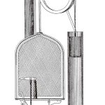
- Figure 1: Section drawing of water-balance elevator, Cyrus W. Baldwin, “Improvement in Elevators.”
-
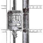
- Figure 2: Water-balance elevator, “The Hydro-atmospheric Elevator,” The Industrial Monthly (April, 1872)
-
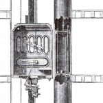
- Figure 3: Water-balance elevator: detail of car and counterbalancing bucket, “The Hydro-atmospheric Elevator”
References
[1] “Buildings,” Chicago Tribune (February 11, 1872).
[2] “Artesian Well,” Chicago Post (February 13, 1872)
[3] Advertisement for “The Water Balance Elevator,” Chicago Tribune (March 7, 1872).
[4] Advertisement for “The Water Balance Elevator,” Chicago Tribune (March 23, 1872).
[5] “Another Fine Building,” Chicago Tribune (April 14, 1872).
[6] “The Hydro-Atmospheric Elevator,” The Industrial Monthly (April, 1872).
[7] “Building Notes,” Chicago Tribune (October 27, 1872).

Get more of Elevator World. Sign up for our free e-newsletter.