Thin Elevator Ropes on Small Sheaves
Jul 1, 2011
This article evaluates the correlation between the ratio of sheave diameter to nominal rope diameter and rope service life.
In recent years, a movement has gained ground in the elevator industry toward the introduction of more compact and smaller designs. Efforts to cut energy consumption and costs have driven down the size of individual components. Historically, the traction sheave along with the drive system were among the most important component assemblies of any elevator installation and formed the basis for the design of the entire machine room. With the advent of the machine-room-less elevator, these constructions have become super-fluous. Reducing the size of the traction sheave inevitably means also reducing the diameter of the means of suspension – which is predominantly still wire rope. However, various standards exist, e.g., the EN 81-1[1], which limit the degree to which the rope diameter can be reduced.
Despite this, in recent years a number of ropes have been brought to the market which exceed these limits. For reasons of cost, these thin ropes are “whetting the appetite” of an ever increasing number of elevator producers, with possibly insufficient awareness of the detrimental effects of a smaller diameter on the service life of ropes. The following article evaluates the correlation be-tween the ratio of sheave diameter to nominal rope diameter D/d and rope service life.
Influencing Factors
How are ropes actually able to move over sheaves? Or in other words, how do ropes repeatedly bend over a radius over a long period of time? Ropes consist of a multitude of individual wires that move against each other. The movement of the wires allows the rope as a whole to bend. Simultaneously, however, this dis-placement brings about relative movements which lead to abrasion. The wires of a rope when running over a sheave are subjected not only to individual stresses but also to a variety of different stresses such as bending, pressure and tension. The amount and type of stress are de-pendent on many influencing factors, primarily resulting from rope construction and elevator installation.
Examples of rope-specific influencing variables include:
- Rope construction
- Wire strength
- Rope core, lubrication and diameter
Examples of installation-specific influencing variables include:
- Ratio of sheave diameter to nominal rope diameter
- Rope loading
- Sheave groove material
- Sheave groove profile
- Deflection angle
- Bending length
In individual cases, other factors such as ambient temperature and humidity can also play a role by in-creasing stress and thereby impacting rope service life. The variety of possible influencing factors makes it impossible to exactly calculate the rope service life. Nevertheless, rea-sonable predictions for the approximate discard age of a rope can be made based on fatigue bending tests.
Service Life Calculation
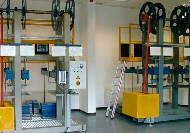
The Institute of Materials Handling Technology and Logistics at the University of Stuttgart has conducted a multitude of fatigue bending tests and statistical analyses. These tests formed the basis for the rope service life calculation devised by Feyrer, which considers the above mentioned factors. Incorporated in the equation is the ratio of the sheave diameter to the rope nominal diameter D/d and also the groove profile.
Influence of the Groove Profile
The groove profile, which subjects the rope to the lowest degree of stress, is the round groove. While the contact pressure on the rope is low, this also results in low traction. Consequently, a greater sheave diameter has to be specified, as its greater/longer contact surface will increase the traction. This entails a high D/d ratio.
However, if the cost benefits previously mentioned are to be achieved, the aim must be to work toward precisely the opposite effect, namely a small D/d ratio. Consequently, a small sheave with an appropriate groove profile is used. Unlike round grooves, groove profiles such as an undercut round or V-groove exert a substantially higher contact pressure, which increases traction. The angle of wrap of the rope around the sheave can then be reduced.
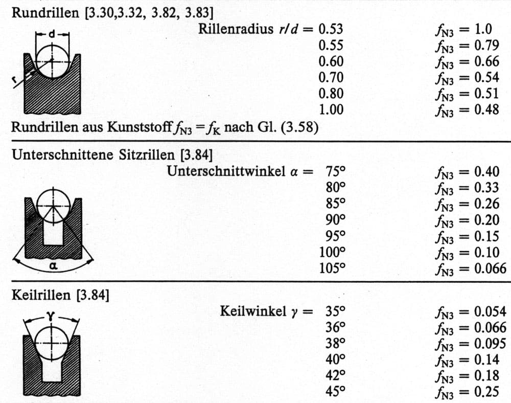
In profiled grooves, the rope is clamped and does not lay completely flat in the groove, and, consequently, the contact surface is reduced. Higher pressure levels are xerted on the remaining contact surface, resulting in a greater tendency to abrasion in these areas. Wire breaks appear earlier and in greater numbers. The more the sheave diameter is reduced relative to the rope diameter, the less the contact area between the rope and the more “aggressive” the groove profile needs to be to achieve the necessary traction. This, in turn, leads inevitably to a reduced rope service life. The influence of the various groove profiles on the service life of the rope is reflected by the influencing factor fN3 (Figure 1). This factor forms part of Feyrer’s calculation of the corrected number of bending cycles NKorr.[2]
NKorr = N fN1 fN2 fN3 fN4
Note: Corrected number of bending cycles NKorr according to[2] the number of bending cycles N and bending cycle factors fN1–fN4
Rope Damage Due to Small D/d Ratio
Tests have shown that with a low D/d ratio and high rope-tension level, the time span between the first appearance of wire breaks and discard age will be relatively short.
Frequently, a piece of an outer strand or pieces of steel core will break, or individual wires inside the strand will be squeezed out of their assembly. Due to the high sur-face pressure in conjunction with high bending stress, the surface of the wires will be destroyed. A “fretting-effect” (frictional slippage) will occur, as under these levels of stress a normally sufficient amount of rope lubrication is no longer effective.[3]
Determination of Service Life According to EN 81-1
In Annex N of the EN 81-1,[1] a method was published for determining the safety factor of suspension ropes which takes into account Feyrer’s service life calculation. Based on this standard, a method was developed by Schiffner[4] “to ensure a minimum service life for ropes with the inclusion of practically all installation parameters impacting on rope service life.” This minimum service life should be 600,000 bending cycles based on a calculation of 100,000 round trips per year applied over three years.
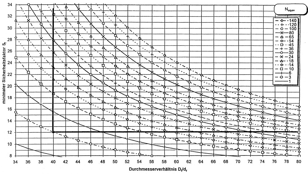
Based on Annex N of the EN 81-1,[1] it is possible by means of a formula or diagram to determine a safety factor for suspension ropes. As evident in the diagram in Figure 2 the minimum safety factor increases with a diminishing diameter ratio D/d and equal Nequiv (equivalent number of deflection sheaves).
Fundamental to the thinking of the EN 81-1 are criteria for the reliable recognition of the discard age of a rope between inspection intervals. The identified safety factor results in a rope drive system with limited service life.
Cost Savings
The requirements of the EN 81-1 may be seen by some elevator manufacturers as a restriction on the develop-ment of cost-saving traction concepts. It is argued that not all applications necessitate the specified 600,000 cycles to be achieved and that consequently the safety factor and the D/d ratio could be lower. For the elevator manufacturer, another possibility to decrease costs is to reduce the number of ropes in an elevator installation. In this case, ropes with a higher breaking strength would have to be employed. Various alternatives to achieve higher breaking strength in ropes have already been identified by the author in other publications[5,6,7]. An increase of the breaking strength can be achieved, for example, by using wire with a higher tensile strength. How-ever, this objective is also restricted by the requirements of the DIN EN 12385[8], which specifies a maximum wire tensile strength of 1770 N/mm2.
Beyond the Limits
Should the defined limits of the EN 81-1 or the DIN EN 12385-5 be exceeded, then a type examination certificate is required which must be issued by an independent testing organization, a so-called notified body. Any such conformity examination certificate must confirm on the basis of comprehensive tests that the means of suspension may be safely used despite deviating from the regulations.
There are two main approaches to prove or confirm the safe use of the rope. Either it can be shown through testing that the rope will achieve 600,000 cycles in spite of the reduced diameter ratio and that the discard age will be reliably recognized, or, alternatively, a lower number of operating cycles is stipulated with the reduced diameter ratio and reduced safety factor on the basis of testing and statistical analysis. Type examination certificates already exist for both of these possibilities.
With the second approach, due attention is paid to the safety aspect by prescribing a reduced number of trip cycles for the rope if a lower safety factor is applied than that prescribed by EN 81-1. In order to guarantee compliance with this trip count, the elevator builder must take additional measures to ensure the safe operation of the installation. The type examination certificate stipulates the installation of a trip counter that shuts down the installation after reaching the allowable number of trips. Using this approach, a D/d ratio of 25 is feasible (the EN 81-1 prescribes a minimum D/d ratio of 40).
Whether or not this type of reduction of the drive sheave diameter is sensible may be questionable. From past experience and a variety of fatigue life tests, it has been established that reducing the D/d ratio will reduce the service life of the rope. According to Vogel[9], “reducing from D/d = 40 to D/d = 33 … already limits the service life of the ropes by a factor of 2.5.” Vogel goes on to explain that “for an 8 X 19 filler rope with fiber core and a nominal diameter d = 12 mm … the bending cycle count at a rope safety of n = 12 increases by a factor of around 8 if the diameter ratio is increased from D/d = 25 to 40.”
Even though a distinction certainly has to be made in the way different rope constructions are assessed in detail, the underlying conclusion to be drawn from Vogel’s findings is that an increasing reduction in the diameter ratio D/d clearly equates to an increasingly curtailed service life. This means that reduction of the D/d ratio from 33 to 25 reduces the service life by twice as much as a reduction of the D/d ratio from 40 to 33. Consequently, the required safety factor as per EN 81-1 increases substantially. If the aim is to minimize the safety factor, then this will inevitably entail incurring the additional costs involved in mounting a trip counter in the elevator installation.
Before rushing into a decision to use a very small and supposedly cost-effective traction sheave, the following aspects should be considered: Decreasing the size of the sheave equates to decreased torque. At the same time, the traction sheave carries out more revolutions at the same elevator speed, causing the sheave temperature to rise. With each trip, the rope passes over the same area of the groove more frequently than when using a large sheave, meaning increased abrasion. Because drive systems for traction sheaves with a diameter of 150 and 200 mm often have the same overall size, no savings are made in terms of installation space.
For its 6.5 mm PAWO 819 W + IWRC and 6.0 mm PAWO F3 ropes, Gustav Wolf has type examination certificates attesting to their use on sheave diameters ≥ 200 mm without additional cost-intensive installation measures. To obtain these type examination certificates, comprehensive bending life cycle tests for the worst-case scenario were conducted. The ropes were tested in the undercut round groove with a 98° undercut angle and in the V-groove with a 40° V-groove. The fatigue bending tests were carried out with a safety factor of 12. In both cases, the discard age of the ropes was clearly identified, whereby the number of trips exceeded the threshold of 600,000. The discard age was determined based on the number of admissible wire breaks according to DIN 15020[10] or after a reduction of the rope diameter of more than 6% according to ISO 4344[11]. It is known that the trip count in more “rope friendly” grooves increases.
This is also evident from the bending cycle factor fN3, according to Feyrer (Figure 1). Consequently, ropes can also be used in grooves with an undercut angle ≤ 98° and in grooves with a V-groove with ≥ 40°. Ropes running in round grooves in a sheave of 200 mm diameter achieved trip counts far above those running in profiled grooves. Even with sheave diameters of less than 200 mm with round grooves, more than 600,000 bending cycles can be attained before the discard age is reached.
Summary
In the planning of an elevator installation, all factors influencing cost must be carefully considered against each other. The trend towards compact installations reduces procurement costs. At the same time, the adoption of smaller traction sheaves reduces the service life of steel wire ropes and traction sheaves. This mutual inter-action between rope and sheave must be factored into the planning process. Otherwise, elevator installations will become more expensive due to the need for subsequent modifications.
If an elevator installation using thin ropes fails to com-ply with the limiting values of the EN 81-1, then this must be compensated by compliance with the requirements of the type examination certificates. Consequently, the answer to the question regarding applicability of thin ropes for elevator installations should actually be: Yes, but … deliberations should focus not only on cost savings and minimization, but also on the safe operation of the elevator installation.
References
[1] DIN EN 81-1:1998+A3:2009(D)
[2] Feyrer, K. Drahtseile – Bemessung, Betrieb, Sicherheit Springer,Auflage, 2000, S. 265-268
[3] Singenstroth, S. Drahtseile leben begrenzt Sonderdruck aus Drahtwelt, Vogel-Verlag, 9/1981
[4] Schiffner, G. EN 81-1 Anhang N: Die Ermittlung des Sicherheitsfak-tors von Tragseilen Lift-Report, Heft 2/2000, S. 52
[5] Wolf, E., Franz, A. Seilentwicklung für Aufzugsanlagen Lift-Report, Heft 5/2005, S. 28-32
[6] Wolf, E., Franz, A. Rope Development for Elevators ELEVATOR WORLD, March 2006, S. 122-126
[7] Wolf, E., Franz, A. Weiterentwicklung erprobter Tragmittel im Aufzugsbau Lift-Report, Heft 2/2009, S. 26-32
[8] DIN EN 12 385-5:2002/AC: 2005(D)
[9] Vogel, W. Quo Vadis Seillebensdauer, Lift-Report, Heft 5/2007,
S. 54-59
[10] DIN 15 020 Blatt 2:1974
[11] ISO 4344:2004
Get more of Elevator World. Sign up for our free e-newsletter.


