Toward Smart Elevators – the KLEEMANN Experience
Mar 1, 2024
With Four Innovations: Passenger Emergency Detection (PED), Electronic Shaft Measurement (ESM), G-Braille Elevator Assistance System for Visually Impaired People and Information on Safe Environment (ISE)
by Dr. Giorgos Georgiadis
This paper was presented at the 2023 International Elevator & Escalator Symposium in Edinburgh, Scotland.
Industries are embracing smart operations due to the unmatched advantages they offer. They provide an operational environment that is more agile, responsive and interactive with the user.
The elevator is a vital piece of equipment for people’s daily lives. For the elevator industry, incorporating smart technology is a necessity — rather than an option — considering the importance it has in daily life.
This paper explores four innovative and smart functions/products for elevators that enhance passenger safety, construction, accessibility and convenience. These functions are:
- Passenger Emergency Detection system (PED)
- Electronic Shaft Measurement system (ESM)
- G-Braille system
- Information on Safe Environment system (ISE)
1. PED, Passenger Emergency Detection System
The PED system aims to automatically detect emergency health situations (such as a heart attack, faint-out) for passengers who are unable to respond during this urgent situation. Through the use of depth cameras and AI algorithms, the system detects a passenger’s loss of consciousness inside the cabin and triggers an immediate reaction by the lift. It initiates a series of actions, such as automatically calling emergency services, moving the elevator to the ground floor, opening the doors and notifying nearby hospitals through the Internet of Things (IoT).
The system using cameras and advanced AI algorithms[1] recognizes the presence of people inside the elevator. The PED system uses technology with depth cameras, which do not record personal data, so they do not fall under General Data Protection Regulations. The incident-detection methodology comprises three steps:
- Detection and tracking of moving items
- Extraction of event features that are indicative of the items’ state
- A Hidden Markov Model (HMM) method that recognizes occurring incidents based on event features
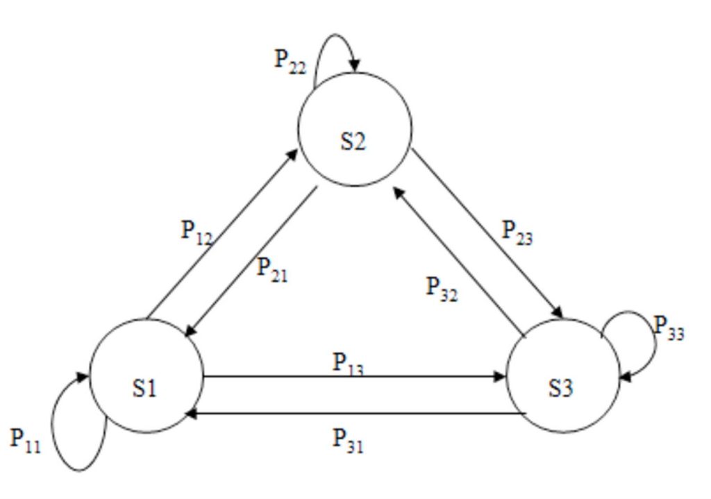
A three-state Markov model (Figure 1) that considers the above event is used to achieve fall detection.
The first state (S1) refers to a non-falling state, e.g., a human standing or slight movement.
The second state (S2) represents the actual fall, which is characterized by highly decreasing vertical velocity (when the height decreases, the velocity takes negative values) and augmenting area variance.
The third state (S3) signifies the end of the fall and declares detection of the incident.
The transition probabilities are based on event features and defined in the following matrix:
The probability F,
constitutes a sigmoid function that favors with high values close to 1, cases with high (negative) vertical velocity and high area co-variance, i.e., cases that correspond to the state of falling. Here, T is a constant defined by training.
Function u,
declares that state S3 that signifies the detection of the fall cannot be reached if the fallen person is not below a loose threshold HT.
In the following schematic (Figure 2), a description of the system is shown.
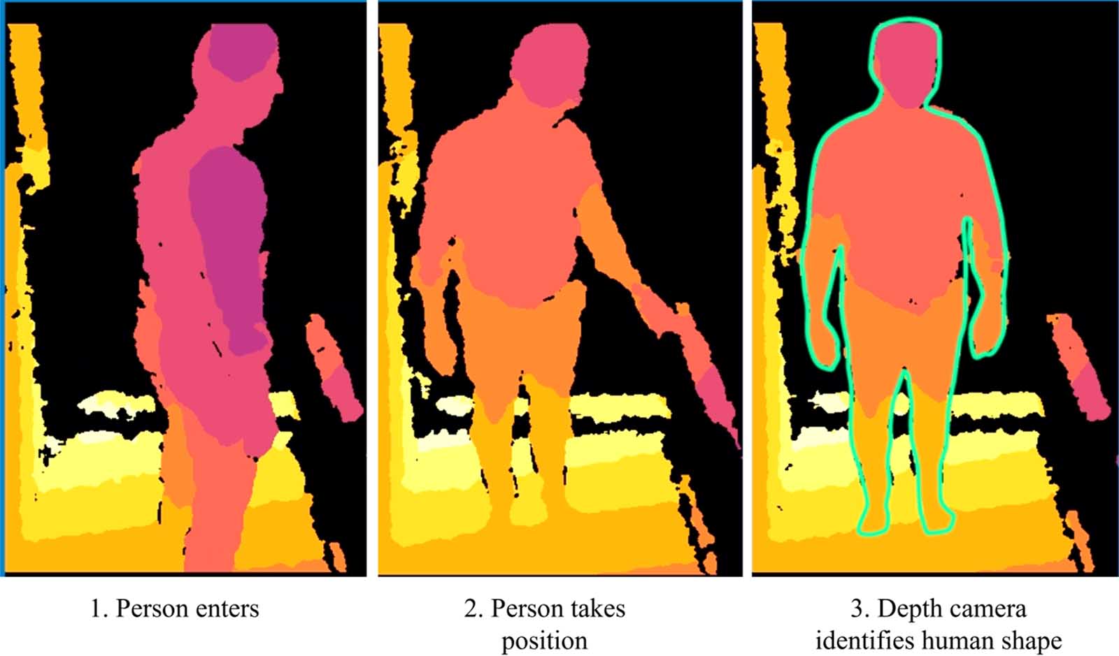
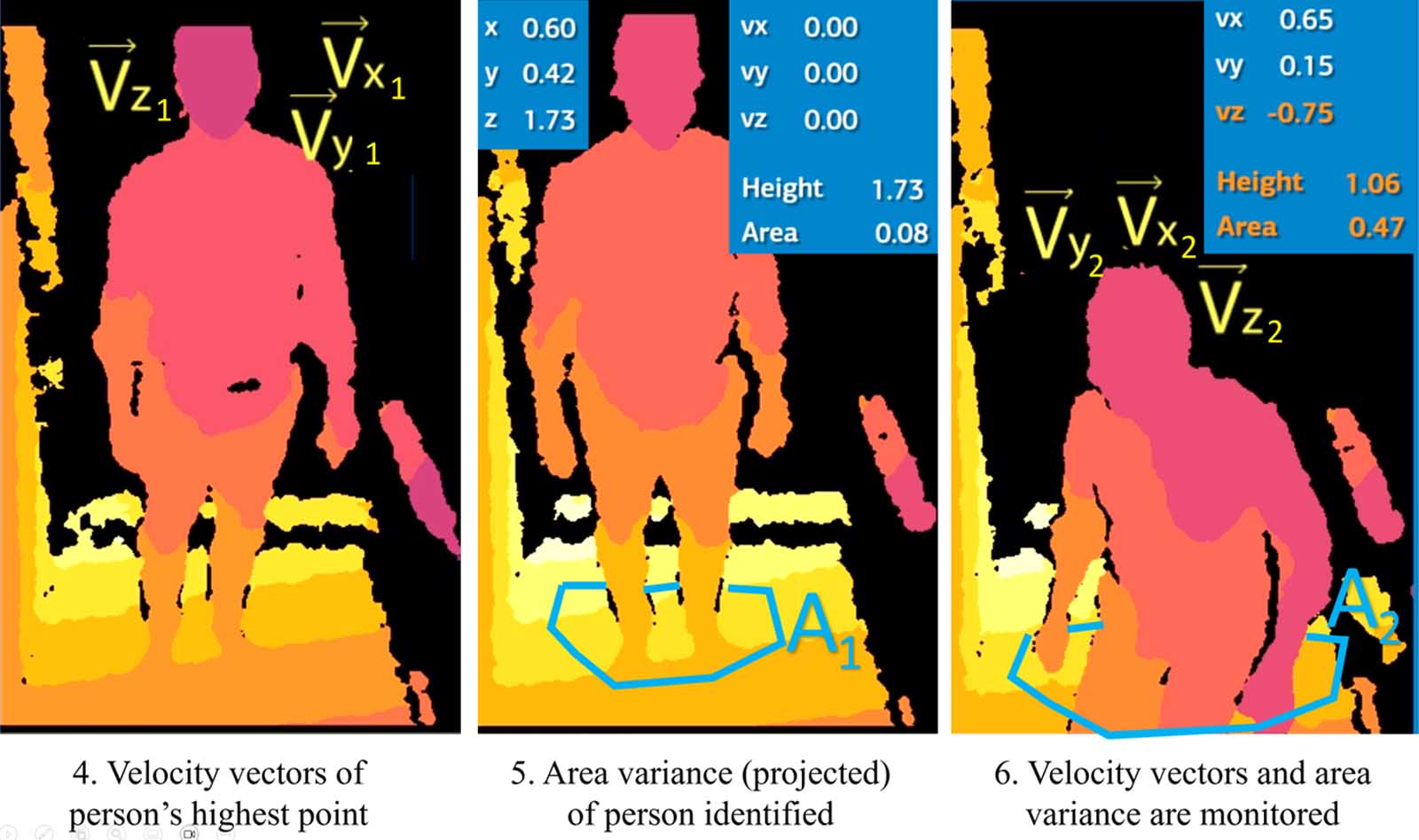
The depth camera and algorithm will recognize the human shape. Specific features will be monitored by the system. The first feature is the vertical velocity of the tracked person’s highest point, which will be measured many times per second for a constant time window. The second feature refers to the area variance. When a person falls, the measured area augments. This feature is measured in the same frequency and time window as the velocity. The last used feature is the height, and apart from its importance to vertical velocity calculation, it facilitates the avoidance of false alarms because a fallen person cannot be higher than 1 m. All these features are extracted from the depth camera. After feeding the novel HMM for fall detection with these three features, a fall probability is extracted as described previously.
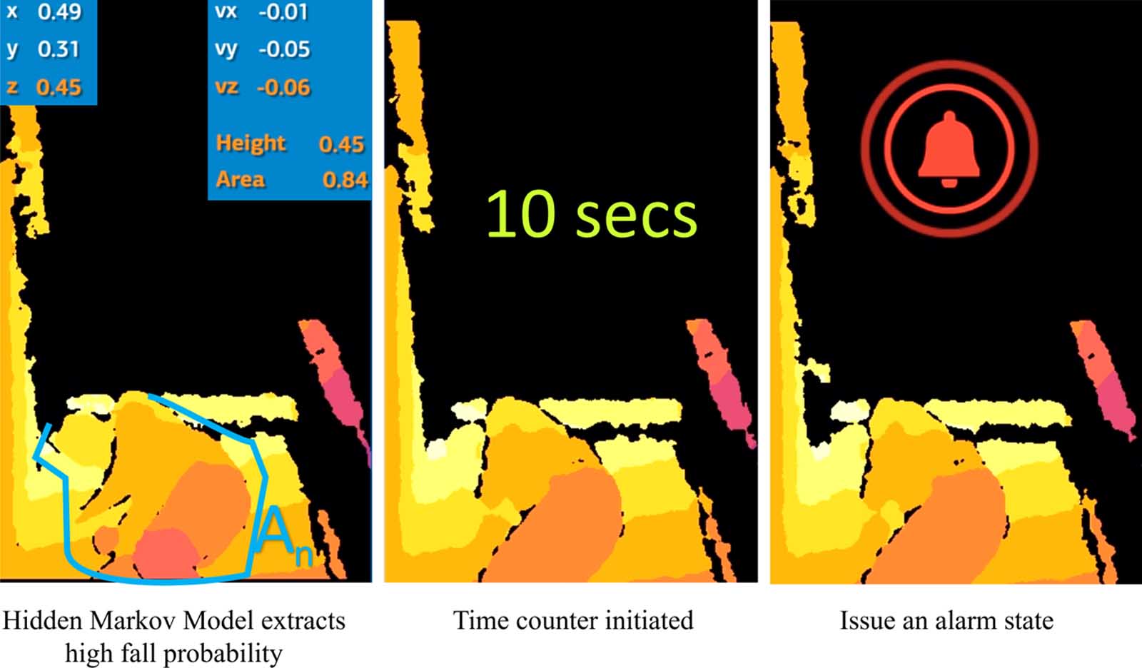
When the HMM extracts high fall probability (Figure 3), the time counter will be initiated. If after a specific limit (10 s) there is no recovery, an alarm state will be initiated. As mentioned earlier, a series of actions, such as automatically calling emergency services, moving the elevator to the ground floor, opening the doors, setting the cabin air fan to maximum supply and notifying nearby hospitals through the IoT, will take place.
PED is a revolutionary system that ensures prompt and efficient response to critical situations 24 h per day, potentially saving lives.
2. ESM, Electronic Shaft Measurement System
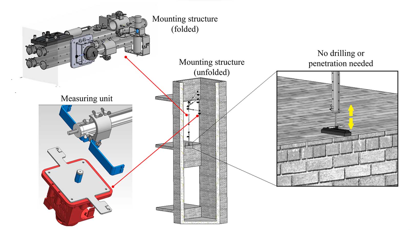
The ESM (Figure 4) is a system capable of automatically measuring the dimensions of an elevator shaft using computer vision approaches and optical sensors without human intervention. The system detects deviations in construction dimensions, deviations from the theoretical vertical direction and mistakes in wall surface dimensions. Additionally, it calculates the maximum available shaft volume for the elevator system. ESM ensures accurate measurements, enabling precise elevator installation and maintenance, thereby improving overall performance and safety.
The ESM tool is light (with a mounting system weighing less than 8 kg), portable and battery-powered. It is mounted on the top floor, and it doesn’t need any wall penetration.
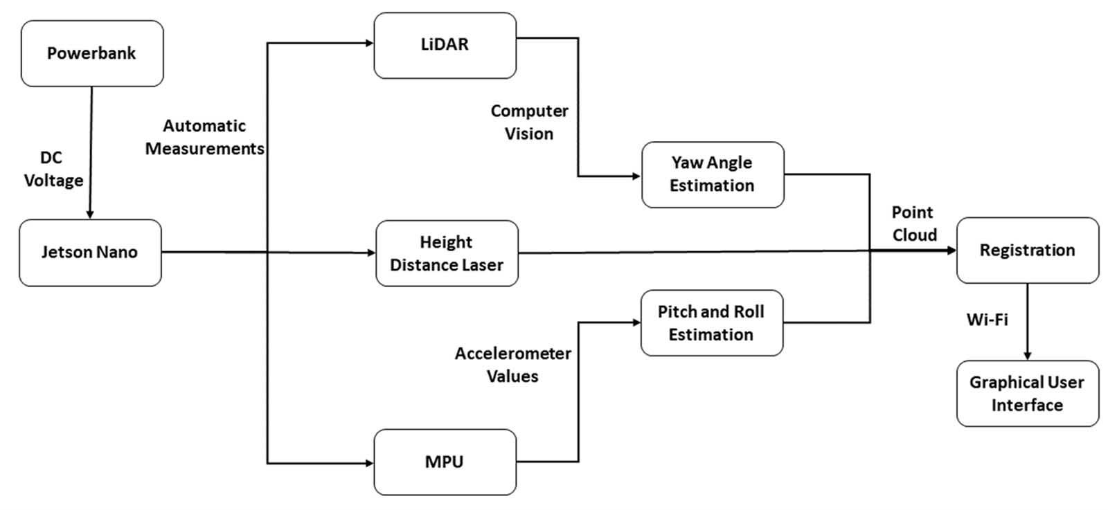
The architectural diagram for the developed measurement system is presented in Figure 5. More specifically, a portable power bank feeds with current the employed computational unit, such as the Jetson Nano, thus providing the ability to carry out several measurements without needing a charge.
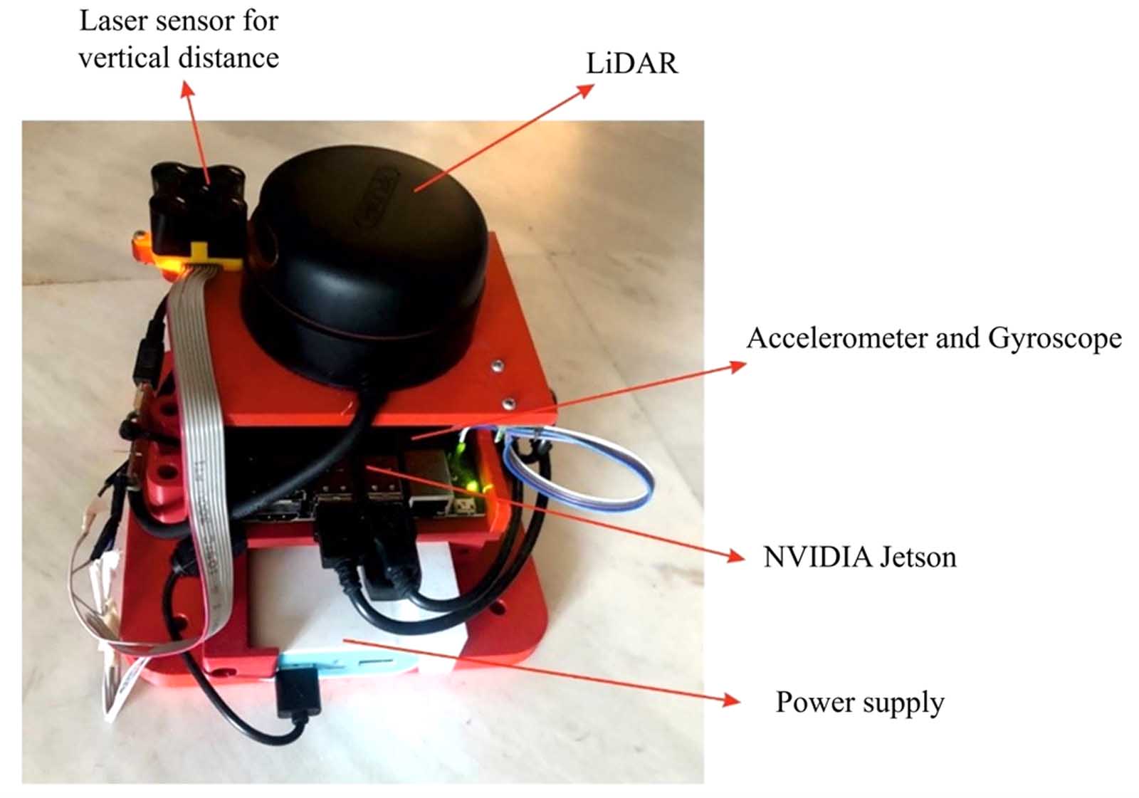
Concerning the measuring unit and applied sensors, three different devices are connected directly to the NVIDIA Jetson computer[2] that is responsible for the communication of the sensors, as well as for the execution of the computer vision algorithms, as illustrated in Figure 6. The first one is a high-resolution LiDAR with 11 rotations per second that provides the horizontal coordinates of the shaft. Whereas, the second sensor is the height distance laser that calculates the device height representing the vertical coordinate. The third is a Magnetic Pickup (MPU) sensor, which is responsible for inspecting the orbit of the experimental arrangement measuring the pitch and roll angles, which can be changed due to small air currents inside the measured shaft. Concerning yaw angle computation, computer vision methodologies are applied.
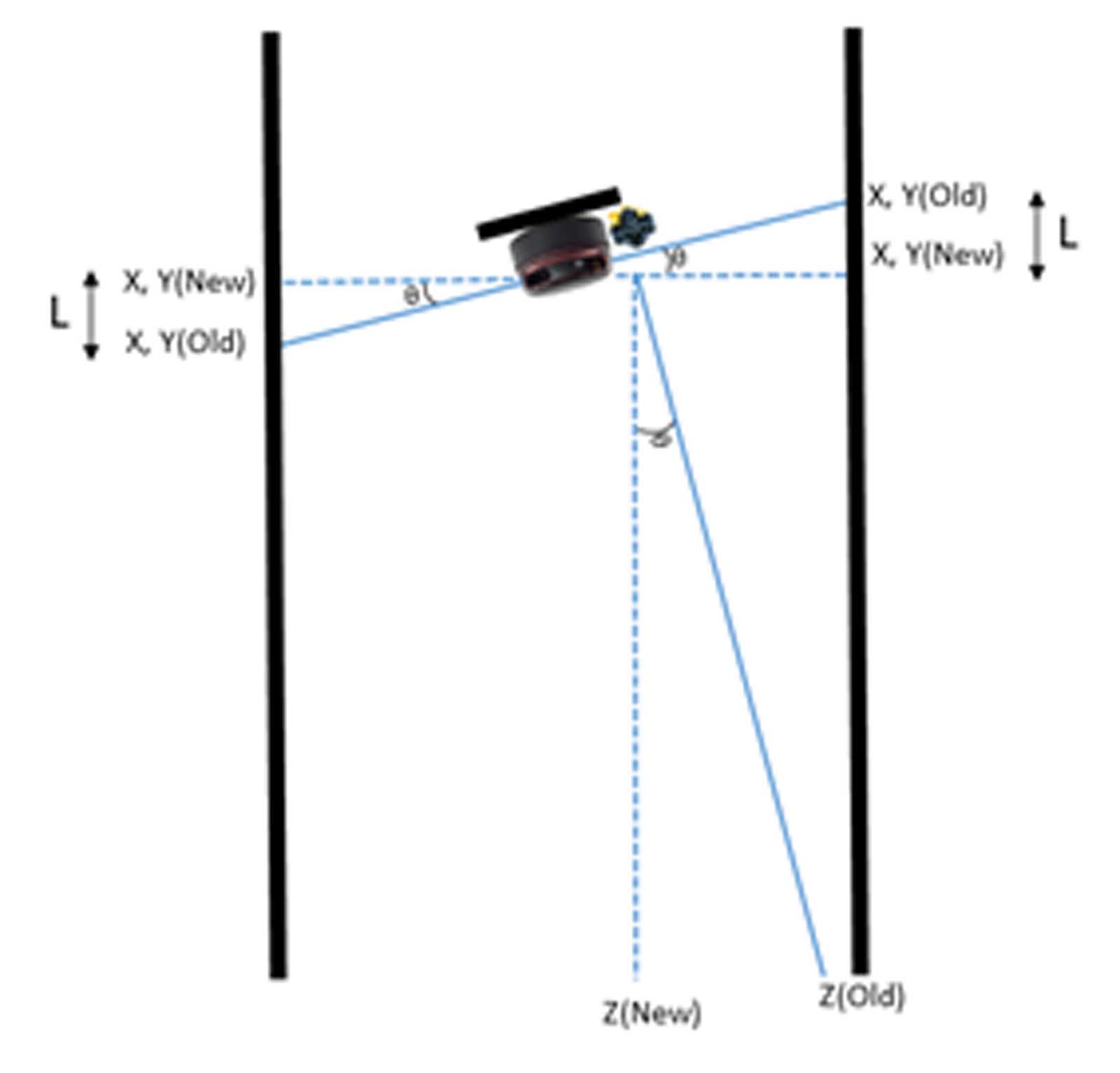
To avoid inaccurate results from uncontrollable rotation of the unit due to air currents developed inside the shaft, an MPU sensor was incorporated. Firstly, the deviations of pitch and roll are calculated and the captured values from the LiDAR (X and Y values) are corrected accordingly. In situations where pitch and roll values are above 3° for more than 10 consecutive seconds, a message appears to the user informing them about the status, suggesting repetition of the process to ensure a reliable measurement. In Figure 7, a pitch deviation is schematically illustrated, coupled with the calculated and the actual values of the X, Y and Z axes.
The system will be mounted on the top floor, as shown earlier, and will start descending with the help of a small electric motor at a speed of approximately 45 mm/s. The algorithm[3] takes data from the LiDAR. Then the roll, yaw and pitch inclinations are calculated. The yaw angle is computed using computer vision techniques, while pitch and roll are derived from the MPU sensor. An algorithm for the registration of the point cloud is applied. In the next step, a method for measuring the max rectangle inside the cloud is applied. Hereupon, the deviations of the shaft compared to the theoretical shaft are extracted, along with maximum elevator shaft (available for installation) and the shaft’s actual inclination, as shown in Figure 8.
Furthermore, several modules, such as a manipulation tool of the cloud point in the 3D space to thoroughly inspect the shaft and a measurement tool that calculates the distance between two selected points of the cloud, were provided, as presented in Figure 9.
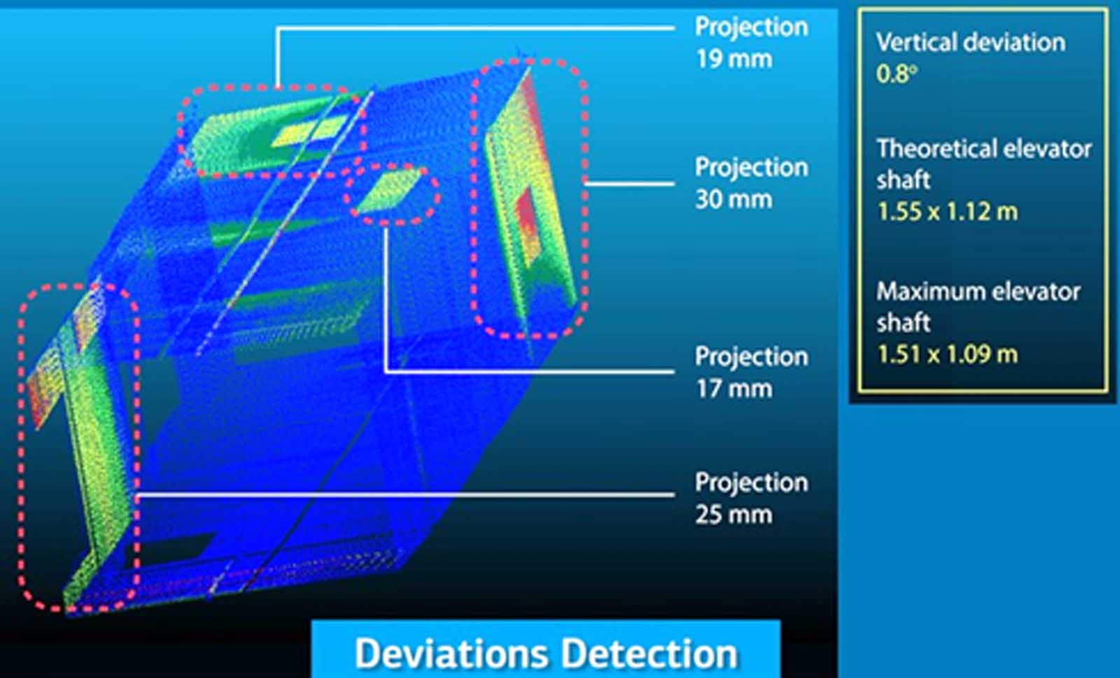
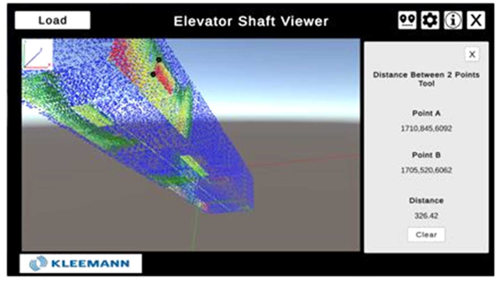
Considering the computation results accuracy and the friendly graphical user interface of the application, the user could easily dimension the investigated shaft, saving hours of manually measuring the interior of the shaft, in turn reaching new, high standards in the demanding lift industry.
3. G-Braille, Assistance System for Visually Impaired People
The G-Braille system (Figure 10) facilitates elevator usage for visually impaired individuals. It consists of a small, compact transmitter with buttons representing the 6-dot braille system that pairs with the elevator controller. Once paired, the visually impaired person can select the desired floor by pressing the buttons in G-Braille according to braille 6-dot coding. With this novel method, the elevator “reads” from the G-Braille transmitter the desired floor without putting a burden on the visually impaired person to “read” by touching all the buttons on the cabin operating panel (COP). This innovative system enhances accessibility and independence for visually impaired passengers.
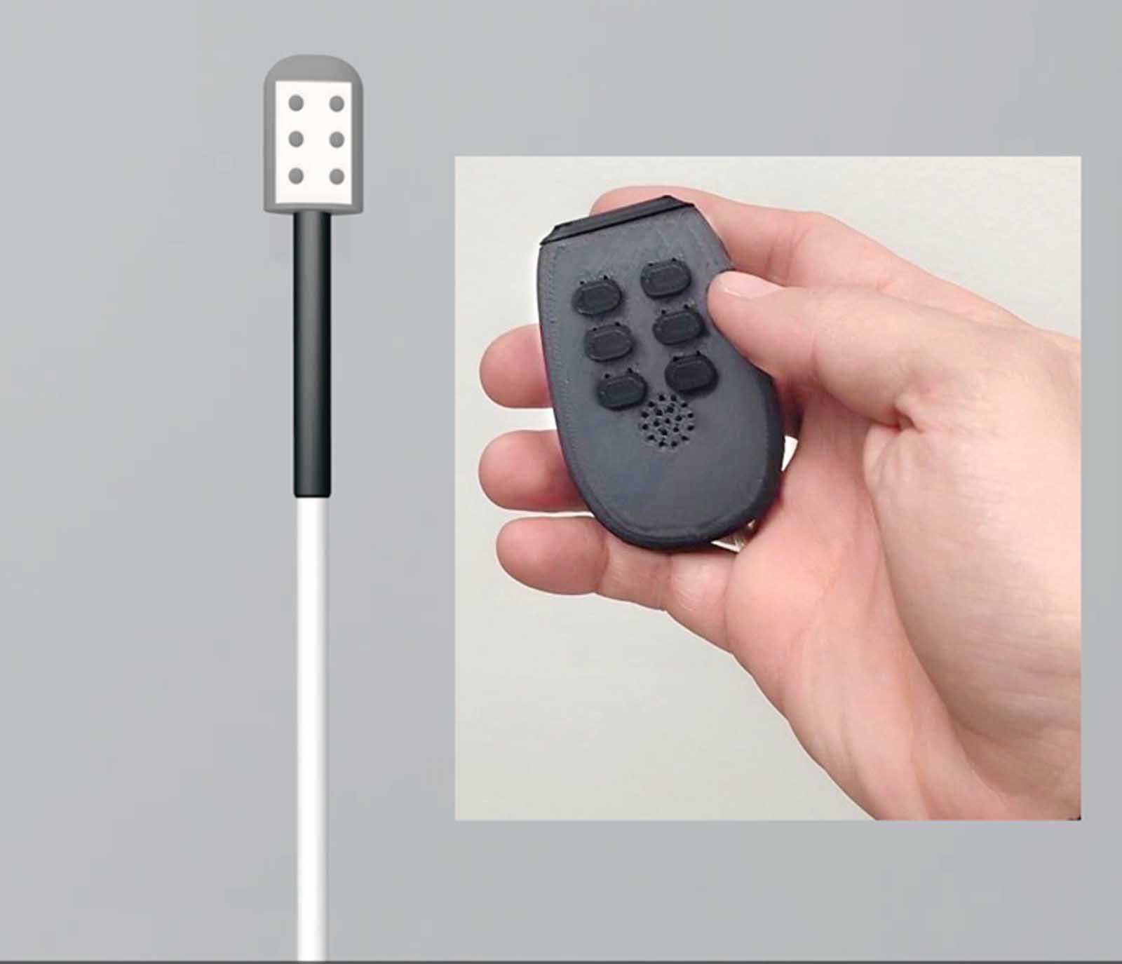
The setup consists of a remote control for each user called “G-Braille,” a floor unit placed inside each landing operating panel of an elevator installation, and finally, a gateway node placed inside the elevator’s cabin called “G-Braille gateway.” All the devices are equipped with a microcontroller capable of Bluetooth Low Energy (BLE) protocol communication. When the remote-control device is powered on, it actively scans for Bluetooth service characteristics initiated by the floor unit and the braille gateway. The floor units’ function is to advertise a Bluetooth service characteristic to which remote devices are in close proximity and can connect and subscribe. After a connection is established for a certain amount of time, the floor unit energizes the push-button box of the floor, thus calling the elevator to the respective floor. After a successful elevator call procedure between the remote control and the floor unit, the latter terminates the Bluetooth session for the remote control to connect to the G-Braille gateway once the cabin arrives.
The remote control connects to the G-Braille gateway through a pairing procedure, and an encrypted link is established. The G-Braille gateway acts as a node in the elevator’s CAN bus network. The user can input commands regarding their floor preference through braille code on their remote-control G-Braille unit to the gateway, which interprets the received commands to selected floors.
A vibrator motor and a buzzer speaker in the G-Braille unit are responsible for notifying the visually impaired individual whether the elevator cabin has arrived or a braille command has been typed successfully. The G-Braille gateway can support up to six simultaneous remote-control connections. Remote devices connected successfully for the first time are bonded to the gateway, and each subsequent connection is automatic without the need of a pairing process. Furthermore, it supports holding a user’s floor preference data, so that a user can be transported to a predefined floor in the future without interacting with the remote control. Figure 11 shows the sequence of events as described in the previous paragraphs.
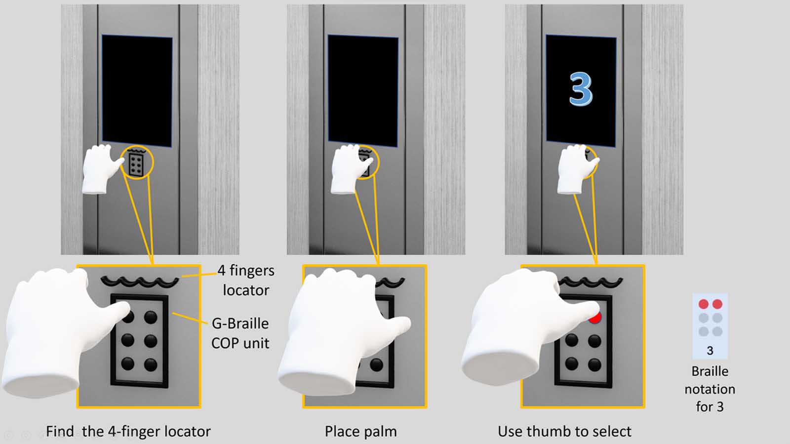
Figure 12 shows another variation of the G-Braille system where the unit is attached permanently to the COP. In that case, the user will try to locate the four-finger locator and then use the thumb to press the G-Braille buttons and select the floor.


4. ISE, Information on Safe Environment
The ISE (Figure 13) system focuses on passenger well-being by providing real-time information about the air quality inside the elevator cabin. It uses a depth camera (which does not record personal data) to collect information on passenger numbers inside the cabin. It provides information such as the last time the elevator(s) was used, the number of occupants during the last ride and the level of air freshness (complete air exchange). Based on research data in 2019,[4] elevator users wish a “pleasant smell in the cabin and clean atmosphere in the elevator.” This preference transformed into an absolute need during the COVID-19 pandemic.
The ISE function covers that need. It informs people waiting to enter the elevator cabin, with parameters related to air quality inside the car, the number of passengers on the last journey of the lift and the number of people inside the car when the elevator is moving. It gives the user an estimate of time to fully recycle air in the chamber, based on correlation functions from the air-circulation system of the cabin. The user who wishes to call the elevator from a stopover (not from the ground floor) while the elevator is moving has information about how many passengers are in the cabin. The user can then decide if they will board the elevator or not or if additional protective measures such as masks are necessary. In cases where a Destination Control System is involved, a mode can be selected that dispatches the cabin with the highest level of recycled air available.

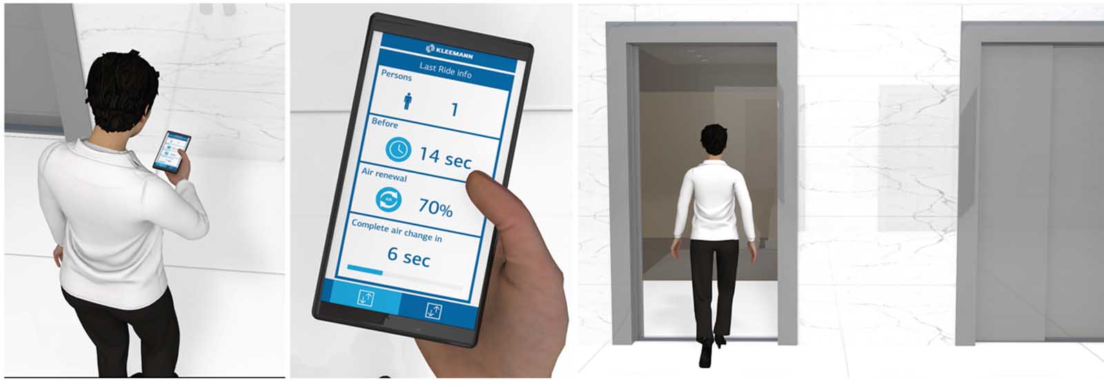
The ISE solution is also available as an app for mobile phones, as shown in Figure 14.
The ISE system provides a simple and convenient information tool to the user regarding expected air quality inside the cabin. In addition, it helps increase awareness for the group of people who are sensitive about health issues.
References
[1] Krinidis, S., Stavropoulos, G., Ioannidis, D. and Tzovaras, D. (2014). “A Robust and Real-Time Multispace Occupancy Extraction System Exploiting Privacy-Preserving Sensors.” ISCCSP.
[2] S. Cass, “Nvidia Makes It Easy To Embed AI: The Jetson Nano Packs a Lot of Machine-Learning Power Into DIY Projects,” [Hands-on] IEEE Spectrum, Vol. 57, No. 7, 2020, pp. 14-16.
[3] Vrochidis Alexandros, Charalampous Paschalis, Dimitriou Nikolaos, Kladovasilakis Nikolaos and Georgiadis Georgios, “Automatic Elevator Shaft Inspection Using a Multi-Sensor Measuring System and Computer Vision Techniques.”
[4] KLEEMANN HELLAS, National Kapodistrian University Athens, Department of Psychology, 2019, “Study of Attitudes, Perceptions About Safety, Fears and Demands of User Regarding Operation of Elevators.”
Get more of Elevator World. Sign up for our free e-newsletter.


