Traction Elevators: A Comparative Study on Wire Rope Stretch
Feb 1, 2018
Evaluating the phenomenon and what to expect in a new installation
Due to the exponential growth of related technology and an increased desire for vertical transportation to achieve higher rises, the mechanical characteristics of the wire rope, as well as its behavior under load, should be studied more carefully in traction elevators. Increase in wire-rope length under load is one of the most noteworthy phenomena in such a situation.
Learning Objectives
After reading this article, you should have learned about:
♦ The expansion characteristics of wire rope
♦ The types of wire-rope stretch and how they are caused
♦ How to calculate the applied load to wire rope
♦ How to calculate and utilize the modulus of elasticity of a wire rope
♦ How the construction and composition of a wire rope affects its elastic characteristics
The longitudinal expansion of wire rope is a source of confusion for the installers, causing difficulties for them. This phenomenon becomes more important in several situations, such as:
- Rope shortening at the initial installation due to constructional stretch
- Adjustment of the car during loading or unloading to ensure leveling accuracy at landings.[1]
It should be noted that, since wire rope is an elastic member, it could become longer under load. Its expansion characteristics and increase in length comes from two sources:
- “The inherent elasticity of its metal components”
- “The compaction process of its wires, strands and core.”[2]
Therefore, the longitudinal expansion of the wire rope occurs in two phases:
- Constructional stretch or initial stretch (permanent)
- Elastic stretch or elongation (temporary)
Moreover, there are other sources of rope increases in length, which are effects of subjects beyond the scope of the elevator industry. They will be discussed briefly at the end of this paper.
Constructional Stretch
Constructional stretch happens right after a load is applied to the wire rope for the first time. In this case, the wires and strands are compressed or pulled together, the bedding down of the assembled wires takes place, strands settle in relation to the core, and the core is compressed, bringing all the rope elements into closer contact.
The result is a corresponding decrease in diameter. This reduction in diameter creates an excess length of wires and lengthens the wire rope. When bearing areas formed on adjacent wires are large enough to withstand the circumferential compressive loads, the decrease in diameter stops. This type of increase in length would consequently be laid off, which, in turn, starts the elastic stretch.[2-5 & 7]
The practical measurement of constructional stretch is influenced by many factors, the most important being the wire rope’s construction and applied load range, and the duty cycle of the elevator.
The construction of the wire rope itself depends on the following factors:
- Type of core (fiber or steel)
- Wire-rope class (number of strands, e.g., 6×19, 8×19, 6×25, etc.)
- Strand construction (Warrington, Seale, Filler)
- Length of lay
- Material (tensile strength of structural steel)[2-5]
For example:
“An eight-strand [wire] rope has a core diameter averaging 22% greater than that of a six-strand [wire] rope. The eight-strand [wire] rope’s constructional stretch is about 50% greater. As to the effect of core type, a six-strand [wire] rope with IWRC has about half (50%) of the constructional stretch of a six-strand fiber-core [wire] rope.”[2]
And:
“[Wire] ropes with wire strand core (WSC) or independent wire-rope core (IWRC) have less constructional stretch than those with fiber cores (FCs). The reason for this is the fact that the steel cannot compress as much as the fiber core.”[4]
The constructional stretch of the wire rope also depends on the load range (shown as a percentage of the minimum breaking load) in which it is operated: the more load applied, the more stretch created. As the American Iron and Steel Institute (AISI), Committee of Wire Rope Producers wrote:
“When constructional stretch just about reaches a maximum at 20% loading, the elastic portion will remain almost straight-line up to around 65%. Total stretch, therefore, as a [percentage] of length, is greater from 0 to 20% than from 20% to 65%, because constructional stretch contributes very little above 20%.”[2]
The heaviest applied load is when the car is stationary at the lowest landing, with its rated load, including the mass of the empty car and components supported by the car, i.e., part of the traveling cable, compensating ropes/chains (if any) and the weight of the wire ropes. In this situation, the major part of the compensating ropes/chains is at the counterweight side and could be ignored. On the other hand, the constructional stretch of the wire ropes will also be affected by their weights. In high rises, where the intrinsic weight of the wire ropes is significant, it affects the practical value of the constructional stretch, as well.[1, 5, 6 & 7]
Constructional stretch occurs during the early periods (first weeks) of the elevator coming into service and stops after a while. It is a permanent and irreversible process; it cannot be calculated precisely and has no elastic properties. To compensate this longitudinal expansion and keep the required clearances between the car/counterweight and buffers, it is necessary to shorten the wire ropes following the installation through slacking and readjusting the rope terminations. The pre-stretching operation, which applies a load to the wire rope greater than its working load but not exceeding its elastic limit, could considerably reduce the constructional stretch of the wire rope.[1-3, 5 & 7]
Since the exact value of constructional stretch for various types of wire rope cannot be calculated, most manufacturers define it as a percentage of the length of wire rope under load. Depending on the competence of the manufacturer, production technologies and equipment, quality of raw materials, etc., the stretch behavior of the wire rope could vary exceedingly.[1, 5 & 6]
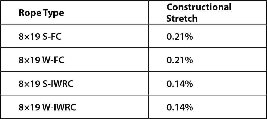
The following examples give some idea about the measure of constructional stretch in various types of wire rope. First, from BRIDON Oil and Gas: “It is not possible to quote exact values for the various constructions of [wire] rope in use, but the following approximate values may be employed to give reasonably accurate results.”[5]
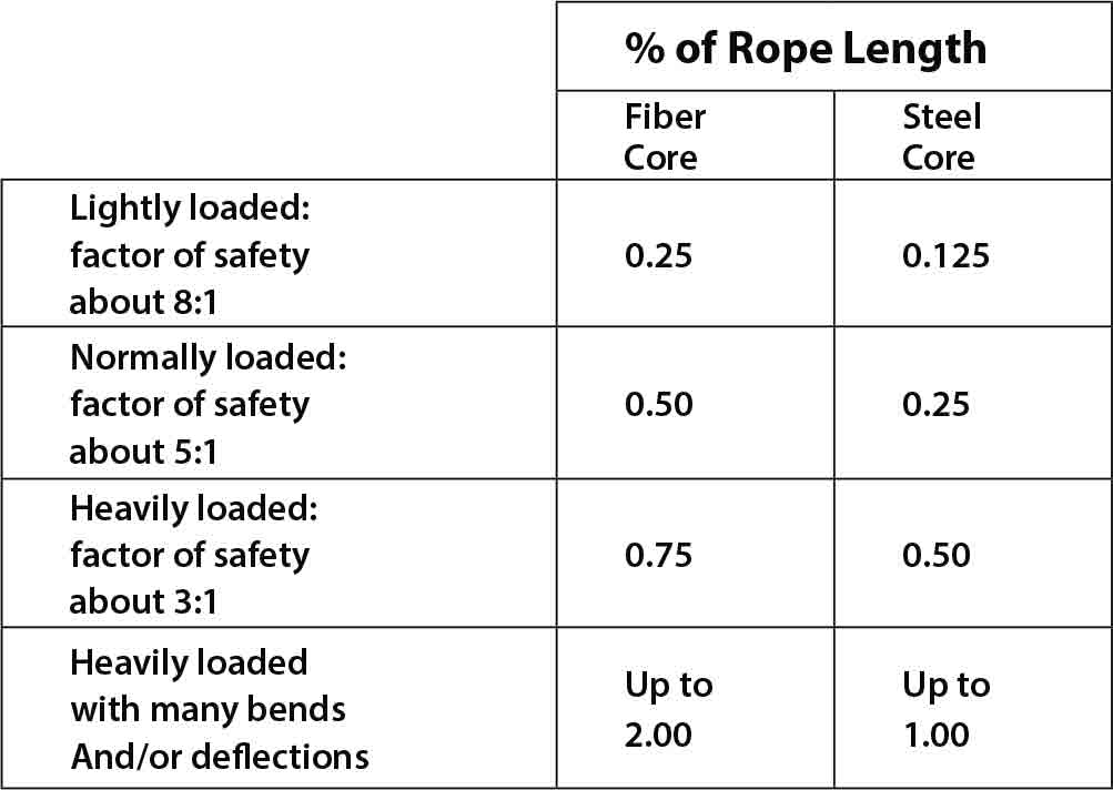
In another reference:
“A definite value for determining constructional stretch cannot be assigned, since it is influenced by several factors. The following table gives some idea of the approximate stretch as a percentage of rope under load.”[4]
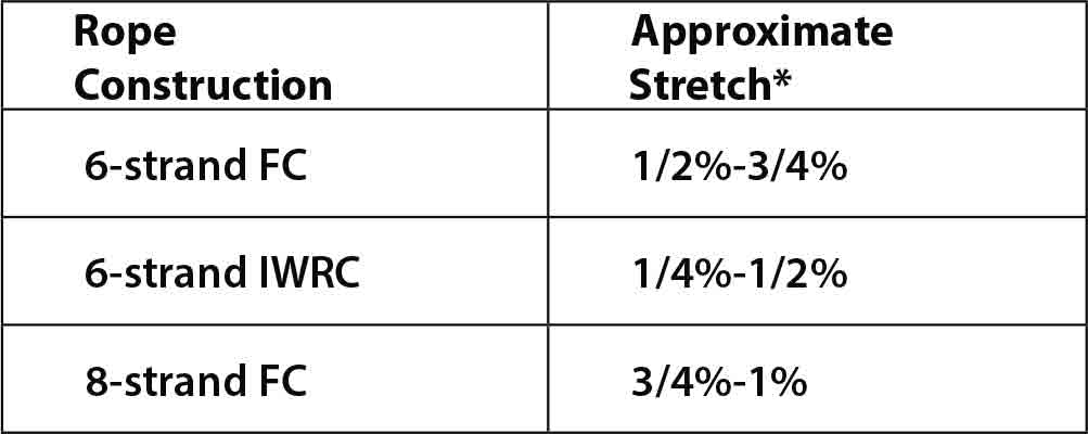
These amounts are based on the values stated in the Wire Rope Users’ Manual by AISI.
CIMAF notes, “On the conventional wire ropes, its value varies approximately from 0.5% to 0.75% of the length of the wire rope under load.”[3] In another source:
“A class 6×19 rope with fiber core has a slightly lower constructional stretch (0.45-0.75%) than a class 8×19 rope with fiber core (0.55-1%). In the case of IWRC, this value depends on the respective rope structure and generally lies between 0.15% and 0.35%.”[1]
This example describes the measurement procedure:
- “The rope is clamped and loaded with less than 2% of minimum breaking load (MBL) in order to align the rope.
- The rope is loaded equally with 10% of the MBL and then unloaded with 2% of the MBL.
- The rope is loaded and unloaded nine times between 2% and 10% of the MBL.
- The evaluation is carried out in the 10th load curve.”[8]
Moreover, some quoted an experimental value for all various types of wire rope to simplify measuring of the shortening adjustment due to constructional stretch: “As the result of experience, the constructional stretch of wire ropes is about 3.5 mm per 1 m in length of wire rope.”[7]
Elastic Stretch
Elastic stretch is the temporary change in length of the wire rope, caused by additional forces applied during loading or unloading of the car. When elastic stretch takes place, the relationship between the change of length of the wire rope and the load range variation is described by Hooke’s Law shown below.[7, 9 & 10]

in which δ is the amount of elastic stretch under load in millimeters; T is the total applied force to wire ropes in Newtons; L is the initial length of wire ropes in millimeters; A is the cross-sectional area of wire ropes in square millimeters; E is the modulus of elasticity of wire ropes in Newtons per square millimeters; and n is the number of wire ropes.
There are three factors in Equation 1, which should be discussed in detail: the first is the cross-sectional area of the wire rope, while the others are the total applied force and modulus of elasticity.
Cross-Sectional Area of Wire Rope
If we pay close attention to the cross-sectional area of the wire rope, we would see that most of the circumscribed area in the wire rope is not used. As a result, the cross-sectional area of the wire rope cannot be determined directly (using the square of its nominal diameter). The cross-sectional area of the wire rope (or, more specifically, the calculated metallic cross-sectional area of the wire rope) is “the sum of the metallic cross-sectional areas of the wires in the [wire] rope based on their nominal diameters,” which could be expressed in this way:[11 & 15]

in which δ is the diameter of each wire in wire rope in millimeters.
We now define a substitute parameter: the nominal metallic cross-sectional area of the wire rope (A), which is “the product of the nominal metallic cross-sectional area factor and the square of the nominal [wire] rope diameter (d)”: [11 & 15]

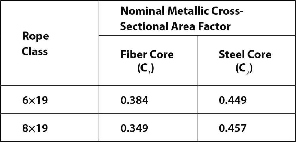
The nominal metallic cross-sectional area factor (C) is the “factor derived from fill factor and used in the calculation to determine the nominal metallic cross-sectional area of a [wire] rope.” The nominal metallic cross-sectional area factor for wire rope with a fiber core is represented by C1, while C2 is used for those with steel core. It is defined by the equation below: [11 & 15]

Where the fill factor (f) is “the ratio between the sum of the nominal metallic cross-sectional areas of all the wires in the [wire] rope (A) and the circumscribed area (Au) of the [wire] rope based on its nominal diameter (d)”:[11 & 15]

For the sake of calculation, the easiest way to determine the cross-sectional area of the wire rope is using the nominal metallic cross-sectional area of the wire rope (A), which needs the nominal wire-rope diameter (d), as well as the nominal metallic cross-sectional area factor (C). This recent factor is obtained from the manufacturers’ data sheets, but if it is not mentioned there, the table below could be used as a reference for the calculations:[11-15]
Calculating the Applied Load to Wire Rope
To determine which masses (forces) have a role in Equation 1, we should first refer to the concept of elastic stretch. System Engineering of Elevators explains: “Elastic stretch occurs throughout the life of the rope and describes the temporary increase or decrease in length of the ropes as the elevator car loads and unloads.”[9] Therefore, the elastic stretch of the wire rope depends only on the rated load, and, despite elevator-related calculations (e.g., traction evaluation, safety factor, etc.), when calculating the elastic stretch of the wire rope, one does not consider the forces due to the mass of the empty car and components supported by the car, nor the weight of the wire ropes. This is because these are permanently suspended from the wire ropes, and their effects have already been considered in their constructional stretch. According to these explanations, the total applied force to the wire ropes (T) will be:

in which Q is the nominal load of elevator in kilograms; i is the reeving factor of the elevator; and gn is the standard acceleration of free fall in meters per second squared.
Modulus of Elasticity (E)
Modulus of elasticity describes the elastic behavior of a solid material under the effect of mechanical stresses. Prior to the yield point, while the wire rope is still in the elastic deformation region, its elastic stretch is proportional to the applied load; therefore, it will act like a linear spring, and its modulus of elasticity could be determined. Modulus of elasticity, also known as the Young’s Modulus, is the ratio of the stress (σ) along an axis to the strain (ε) along that axis in the range of stress, in which Hooke’s Law holds, in the linear-elastic portion of the stress–strain curve.[10 & 16]
The increase in length clearly depends on the modulus of elasticity of wire materials, but the wire rope modulus of elasticity, which describes the elastic stretch behavior of the wire rope, differs from the modulus of elasticity of the wires due to the cross-sectional structure of the wire rope. The stress–strain curve of the wire rope is nonlinear and depends on tensile stress, and, consequently, on the applied load to the wire rope.[16]
Since there are various methods for specifying the modulus of elasticity, producing a wide divergence in the measured amount, ISO 12076:2002 is the uniform testing method for determining the modulus of the wire rope. In this, a load equivalent to 10% of the minimum breaking load is applied, the extensometer is attached and zeroed, then the gauge length (li) is measured. The wire rope is loaded increasingly up to 10% of the minimum breaking load (F10%), and the extensometer reading is recorded (x10%). Next, the load is increased to a value of no greater than 30% of the minimum breaking load (F30%), and the extensometer reading is noted (x30%). According to Hooke’s Law, modulus of elasticity (E) is calculated using Equation 7:[1, 8, 10 & 17]

in which Ac is the calculated metallic cross-sectional area of wire rope in square millimeters; li is the initial length of the test piece in millimeters; x10% is the extensometer reading at F10% in millimeters; x30% is the extensometer reading at F30% in millimeters; F10% is 10% of minimum breaking load in Newtons; and F30% is 10% of minimum breaking load in Newtons.
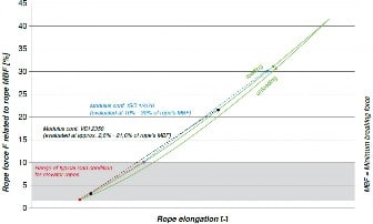
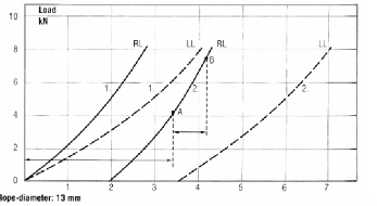
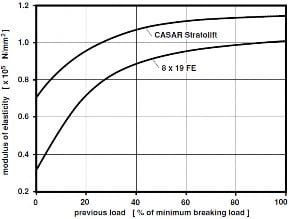
Note that, “It is important, too, to recognize that wire ropes do not possess a normal modulus of elasticity, but an “apparent” one, which can be determined between fixed loads. This is referred to as the [wire] rope modulus.”[17] For example, Figure 1 provides the test results according to the mentioned method as a comparison between regular and Lang lay, showing the higher elastic stretch of the wire rope using Lang lay construction.[1] CASAR Drahtseilwerk Saar GmbH presented a comparison between the modulus of elasticity of an 8×19 FE and the modulus of elasticity of its own product (Figure 2).
These figures clearly show that the modulus of elasticity varies among different types of wire rope, manufactured with different construction and produced by various manufacturers. A complicating issue here is that:
“Modulus of elasticity of a wire rope increases during its service life, depending on its construction and the conditions under which it is operated, such as intensity of the applied loads, constant or variable, bends, and vibrations to which it is submitted. The modulus of elasticity is smaller on the new or unused [wire] ropes, being that for used or new pre-stretched [wire] ropes, the modulus of elasticity increases approximately 20%.”[3]
However, the values of the modulus of wire-rope elasticity are noticeably much smaller than the modulus of elasticity of steel. Also, due to the helix-like shape of the wire rope and compared to the modulus of elasticity of the solid rod, this amount is nonlinear. As it occurs in constructional stretch, the modulus of elasticity increases with load. The more load applied, the higher the modulus of elasticity. Accordingly, many manufacturers state modulus of elasticity of their products, with regards to the minimum breaking load of the wire rope, or represent it on a diagram.[2, 4-6, 8 & 9]
The following examples show the values of modulus of elasticity in various types of wire rope. AISI provided the approximate modulus of elasticity for some wire ropes:[2]
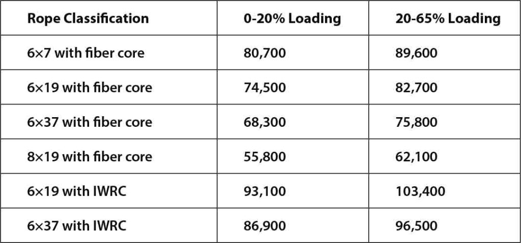
Note that the above measures are in Newtons per square millimeter. Values are rounded up after converting them from Imperial to metric.
According to CIMAF, “The approximate modulus of elasticity of the usual constructions of new wire ropes:”[3]
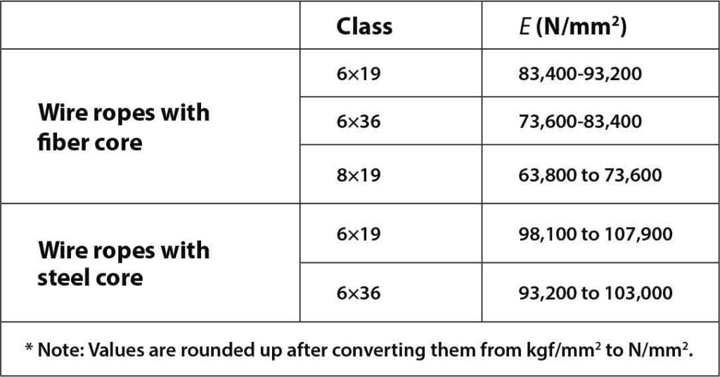
Another source explains that, from zero through 20% of the minimum breaking load, the modulus of elasticity for a 6×19 rope with fiber core is 74,500 N/mm2 and 93,100 N/mm2 for a 6×19 rope with IWRC core. If the applied load varies 21-65% of the minimum breaking load, the moduli of elasticity are, respectively, 82,700 N/mm2 and 103,400 N/mm2 (applicable to the new wire rope).[4]
Some other source quoted 103,000 N/mm2 as the modulus of elasticity of a class 6×19 rope with IWRC core at 20% of minimum breaking load.[5] According to Gustav Wolf Seil- und Drahtwerke GmbH & Co. KG:
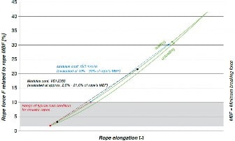
“The graph below shows that the typical load range in elevator design varies between approximately two to 10% of the [wire] rope’s minimum breaking force. . . . An E-Modulus established in this load range is usually lower in comparison to increased load ranges, while the expected elongation per load increment will be higher.”[8]
Finally:
“According to Schweizerische Seil-Industrie AG, the modulus of elasticity of steel wire is 196 kN/mm2 and varies with steel ropes:
1–1.25 × 10⁵ N/mm2 for stranded wire ropes with steel core and 0.7–1 × 10⁵ N/mm2 for stranded wire ropes with fiber core.”[18]
Since the value of modulus of elasticity for various types of steel has been obtained experimentally and tabulated in the handbooks of engineering materials, ignoring the effect of different compositions and previous treatments varying between 190 and 220 GPa, the smaller modulus of elasticity of the wire ropes is shown by the above citations.
Also, these citations show that it is not rational to consider a narrow limit for modulus of elasticity for all types of wire rope. Regarding the significant variation in the construction of wire ropes, it is not entirely possible to define a unique modulus of elasticity for all wire ropes to make an accurate estimation of the elastic stretch, determining the expansion per meter in the wire rope with a specific applied load after a defined period of time or at the end of its service life. Any credible design, calculation or analysis should be based on data provided by the manufacturer.[5 & 19]
Other Sources of Stretch
Practically, there may be other sources of stretch. One is when a load is applied — a result of the wire rope’s tendency to rotate on its own axis. In this situation, the strands spin and unlay themselves, either because of using a swivel or due to a load rotating around the axis of the wire rope, causing lengthening of the wire rope. Since the ends of the wire ropes are fixed to the car/counterweight, this kind of expansion is out of the scope of this paper.[2 & 4]
Moreover, when the applied load exceeds the yield point, non-elastic permanent stretch (plastic behavior) occurs. Once the yield point is passed, any increase in the applied load causes a greater permanent stretch until the wire rope fails due to fracture. Since the suspension ropes in traction elevators are designed with a safety factor of at least 12 (which should not be less than that calculated according to EN 81-50), this increase in length is unrealizable. Eventually, the thermal expansion of the wire rope should be noted. Over small temperature ranges, the linear nature of the thermal expansion leads to change in the length, proportional to the initial length and change in temperature. The linear thermal expansion of the wire rope could be shown as follows:[5]

in which ∆l is the amount of wire-rope expansion in millimeters; li is the initial wire-rope length in millimeters; ∆T is the change in temperature in degrees Celcius (°C); and α is the coefficient of linear expansion (1/°C).
Conclusion
When selecting the wire rope as a major part of elevators, in addition to the safety factor, reeving factor, type of installation, service life and choosing the right construction depending on geometry of sheave grooves, the stretch behavior of the wire rope should be evaluated. Since the constructional stretch behavior of the wire rope is not proportional, it cannot be calculated. Likewise, Hooke’s Law does not estimate the exact elastic stretch of the wire rope, as its modulus of elasticity cannot be measured precisely. These characteristics not only vary among different types of wire rope, but also depend on the installation factors (such as capacity, the mass of the empty car and components supported by it, travel, etc.). Therefore, the amount of stretch (constructional or elastic) of the wire rope should be stated by the manufacturer.
Acknowledgment
This paper was supported by Shirin Sadat Safavi and Amir Reza Hashemi. The author thanks them for their insight and expertise.
Learning-Reinforcement Questions
Use the below learning-reinforcement questions to study for the Continuing Education Assessment Exam available online at www.elevatorbooks.com or on p. 119 of this issue.
♦ What are the most important influencers on the practical measurement of constructional stretch?
♦ How does load on a wire rope impact its constructional stretch?
♦ What is considered wire ropes’ heaviest applied load?
♦ What is the proper wire-rope measurement procedure by which to evaluate constructional stretch?
♦ What is Hooke’s Law, and for which purpose is it used?
References
[1] Scheunemann, W.; Vogel, W.’ and Barthel, T. “Steel Wire Ropes for Traction Elevators: Part Three,” ELEVATOR WORLD, September 2009.
[2] American Iron and Steel Institute, Committee of Wire Rope Producers. Wire Rope Users’ Manual, 4th Ed., Washington, 2005.
[3] CIMAF. Wire Rope: Technical Manual, April 2013 (www.cimafbrasil.com.br).
[4] Hanes Supply Inc. “Wire Rope 101” (www.hanessupply.com).
[5] BRIDON Oil and Gas. “Steel Rope Technical Information” (www.bridon.com/uk/oil-and-gas-ropes).
[6] CASAR Drahtseilwerk Saar GmbH. “Special Wire Ropes: Technical Documentation” (www.casar.de).
[7] Fasihi, I.; Hashemi, O.; and & Nasiri, A. Comprehensive Guide to Elevators and Escalators, Vol. II, 2nd Ed., Tehran: Nowavar, 2013.
[8] Gustav Wolf Seil- und Drahtwerke GmbH & Co. KG. “Elevator Ropes and Accessories” (www.gustav-wolf.de).
[9] Andrew, J. P. and Kaczmarczky, S. System Engineering of Elevators, Elevator World, Inc., 2011.
[10] Rheinberger, S. J. “Selecting Wire Rope Design Factors in Cable Yarding,” Oregon State University, 1992
[11] EN 12385-2:2002+A1:2008. “Steel Wire Ropes — Safety — Part 2: Definitions, Designation and Classification.”
[12] EN 12385-4:2002+A1:2008. “Steel Wire Ropes — Safety — Part 4: Stranded Ropes for General Lifting Applications.”
[13] EN 12385-5:2002. “Steel Wire Ropes — Safety — Part 5: Stranded Ropes for Lifts.”
[14] ISO 4344:2004. “Steel Wire Ropes for Lifts — Minimum Requirements.”
[15] ISO 17893:2004. “Steel Wire Ropes — Vocabulary, Designation and Classification.”
[16] Feyrer, K. Wire Ropes: Tension, Endurance, Reliability, Berlin, GE: Springer, 2007
[17] ISO 12076:2002. “Steel Wire Ropes — Determination of the Actual Modulus of Elasticity.”
[18] Janovsky, L. Elevator Mechanical Design, 3rd Ed., Elevator World, Inc., 1999.
[19] Cambridge University Engineering Department. Materials Data Book, 2003 Ed.
Get more of Elevator World. Sign up for our free e-newsletter.


