Variable-Frequency Drive Systems for Hydraulic Elevators
Oct 1, 2011

An overview of the flexibility and various types of energy-efficient hydraulic drives
An Overview
Elevators with hydraulic drives are flexible by definition. Almost infinite configurations of elevator and cabin designs are possible, a marked contrast to the somewhat limited mass-produced machine-room-less traction standard. The debate about climate change has triggered even more customer focus on energy efficiency. Some even jumped to proclaim the demise of the hydraulic elevator. However, it is now clear that with the right type of hydraulic drive, a hydraulic system can obtain class B energy efficiency.
Learning Objectives
After reading this article, you should have learned about:
♦ Why variable-speed drives are important
♦ Which type of variable-speed drives are useful for different applications
♦ Conventional ride types with electronic control
♦ How mechanical and electric control valves differ in their effects on the elevator system
♦ The effects of frequency-controlled up and down rides on the elevator system
♦ What to use when power connectivity is limited
♦ The benefits of and applications of use for recovery and hydraulic recuperation
♦ How to best deal with high ride frequency
♦ Load-dependent speed reduction
Driven by a global discussion about energy efficiency, some providers of hydraulic drives have tackled this issue by bringing variable-frequency drives into their product range. These are presented as the perfect solution to the energy-conscious customer. Taking a closer look, the technically literate and critical observer will notice considerable differences between the various offerings. This article is designed to help the interested reader differentiate between the various types of energy-efficient hydraulic drives.
The Need for Variable-Frequency Drives
Irrespective of their use in traction or hydraulic systems, variable-voltage, variable-frequency (VVVF) elevator drives reduce energy consumption during the ride. The drawback is a relatively high standby energy usage. Conventional hydraulic drives use no energy at all during standby and are, therefore, perfect for infrequently used elevators (Usage Class 1). Using Bucher Hydraulics’ electronic valve, these drives have been rated B according to VDI 4707 for 30 years. New designs of elevator control systems and VVVF drives now have much lower standby usage; therefore, VVVF drives have become a viable solution across a broader range of applications.
Types of Variable-Frequency Drives
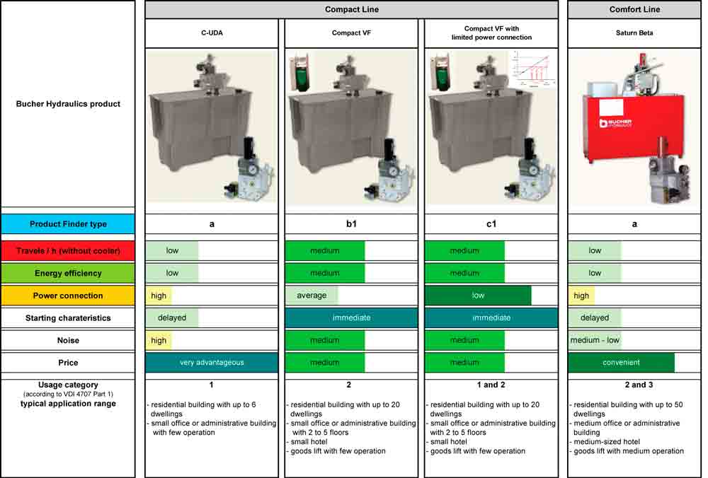
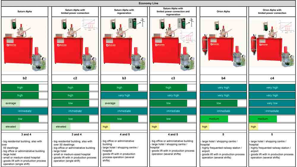
Variable-frequency drives for hydraulic elevators are no novelty, having been built and installed successfully by Bucher Hydraulics worldwide since 1996. At Interlift 2009, a number of other manufacturers presented their own types of variable-frequency drives. There are marked differences between them (Table 1).
Conventional Up and Down Ride (Type a)
In a conventional hydraulic drive, after the start signal, the submerged motor runs up from zero to the maximum number of revolutions (typically 2,800 rpm). The pump delivers the maximum possible flow. To move up out of the starting level and stop at the destination level, speed needs to be controlled. This is done using a mechanical (two-speed) or electronic (variable-speed) control valve, which allows excess oil to flow back to the tank. More oil is pumped than is effectively used. This practice is not only poor for energy efficiency but also heats up the oil unnecessarily: Energy is converted to heat when the oil flow is diverted in the valve. Oil diversion in the valve also generates a certain level of noise.
| Up Ride ▲ | Down Ride ▼ | Type |
| Conventional | Conventional (electronically controlled) | a |
| Frequency-drive controlled (VVVF) | Conventional (electronically controlled) | b1 |
| Frequency-drive controlled (VVVF) | Frequency-drive controlled (VVVF) | b2 |
| Frequency-drive controlled (VVVF) | Frequency-drive controlled (VVVF) with recovery | b3 |
| Frequency-drive controlled (VVVF) | Variable-frequency drive with hydraulic recuperation | b4 |
| Frequency controlled with load-dependent speed control (limited power connection) | Conventional (electronically controlled) | c1 |
| Frequency controlled with load-dependent speed control (limited power connection) | Frequency-drive controlled (VVVF) | c2 |
| Frequency controlled with load-dependent speed control (limited power connection) | Frequency-drive controlled (VVVF) with recovery | c3 |
| Frequency controlled with load-dependent speed control (limited power connection) | Variable-frequency drive with hydraulic recuperation | c4 |
In the following, the expression “conventional” will only refer to an electronically controlled valve. The LRV-1 works independently from temperature or pressure fluctuations thanks to a patented internal feedback loop. The ride curve can be set only once, with no tolerances or seasonal resetting required. A hydraulic elevator using an electronic valve uses approximately 30% less energy than the same one using a mechanical valve.
The mechanical valve is expected to be rendered obsolete in areas subject to the EN 81 standard by the adoption of Annex 3 to EN 81-2. It will become too difficult to achieve the required leveling precision of ±10 mm and redundancy requirements. (In comparison, Bucher Hydraulics’ LRV-1 levels to ±3 mm.) Electronic valves such as the iValve have integrated redundancy and the capability for remote access.
Frequency-Drive-Controlled Up Ride (All b Types)
Using a variable-frequency drive for the up ride, only as much oil is pumped as is effectively required. The speed of the motor/pump combination is controlled directly by the VVVF drive, and the same flow feedback signal is used as for the electronic valve. VVVF drive control has an advantage of faster starting: the motor starts immediately without needing the 2-3 s. for Star Delta switchover. The actual motor rating is, however, no different with VVVF drives than for the conventional system.
The difference in energy consumption between VVVF-drive-controlled and conventional drives is realized during startup and slowdown. This means that the shorter the full-speed run is compared to the entire run time (or, the shorter the rides), the larger the energy-saving potential. The maximum number of rides without oil cooling is also higher.
Load-Dependent Speed Reduction/Limited Power Connection (All c Types)
Most installed passenger elevators rarely run at full load. The typical run is more like this: The customer calls the empty elevator, then rides up to the destination floor. The elevator is, however, designed to handle maximum load during every ride. This means that the power supply needs to be dimensioned accordingly. Often during modernizations, the power supply into the building is limited, and increasing this can be complex and expensive. A current limiter can be the solution: If the load increases over a defined threshold (example: empty cabin plus one passenger), ride speed is automatically reduced, and current requirement remains below the threshold. In this way, the power-feed requirement can be reduced by up to 40% versus full-load/full-speed requirements. A VVVF drive is a prerequisite for this system to function.
Frequency-Drive-Controlled Down Ride (b2 and c2 Types)
During the down ride, oil is run back into the tank through the pump, driving the motor as a generator. The power thus generated cannot be used by a standard variable-frequency drive and is therefore “burnt off” using a brake resistor or similar device. The difference when compared to the conventional drive is that the heat no longer goes into the oil through flow diversion in the valve but can be dispersed anywhere (for example, in the lift shaft) through the brake resistor. The main advantage here is that the number of possible rides without required oil cooling rises significantly (typically up to 120 rides per hour).
Frequency-Drive-Controlled Down Ride with Recovery (b3 and c3 Types)
During the down ride, potential energy is converted into electrical energy. To do this, the pump motor acts as a generator. The power thus generated is converted by a special recovery unit and can then be fed back into the power grid. As a result, 30% of the energy that would otherwise be lost can be recovered. Instead of a separate recovery unit, a variable-frequency drive that has the recovery unit fitted inside the same enclosure is now often used.
Frequency-Drive-Controlled Down Ride with Hydraulic Recuperation (b4 and c4 Types)
In this type of system, a part of the potential energy is stored in a pressure accumulator. During the down ride, a high-pressure pump mounted on the same axis as the main pump/motor combination pumps oil into an accumulator, where it remains stored at high pressure. For the up ride, pressure is released to assist the main motor to drive the main pump. This system allows for another 30% energy savings versus the energy use of the standard VVVF drive. Only the load requires additional power. This high-end system not only saves energy through the hydraulic counterweight, but also works with a smaller motor, and therefore has a lower power feed requirement.
Reasons for Using Variable-Frequency Drives with Hydraulic Power Units
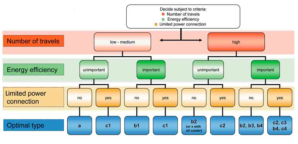
In the previous section, we saw that there are many different ways to utilize variable-frequency drives. Each type has its own specific application, with different weighting and gray areas between them. Figure 2 helps the customer select the right drive type for specific applications.
Number of Travels:
High Ride Frequency
High-ride-frequency units include b2, b3, b4 and c2, c3, c4 types. Their applications are in airports, railway stations, shopping centers, hospitals, hotels, etc. The variable-frequency drive helps to reach a high ride frequency in two ways:
Up ride: no more oil diversion during startup and slowdown of the elevator
Down ride: heat generated does not go into the oil by using the motor as generator.
Previously, oil coolers were used for this type of application. At first sight, this seems the less expensive solution. However, oil coolers require fresh or even chilled air to function properly. The user must, therefore, provide for machine-room ventilation or air-conditioning, depending on environmental conditions. Oil coolers are also noisy, require space and use energy. Bucher Hydraulics believes using a variable-frequency drive is the more cost-effective solution over the long term.
Oil heating is not the only issue for this type of high-ride-frequency application. The power unit itself and all other system components must be dimensioned correctly for the extra load. It is irresponsible to use a conventional system and simply add a VVVF drive. The pump, for example, has very different loadings when pumping upward as when driving the motor as a generator; this needs to be taken into account when selecting materials and design. There are significant differences between the various offerings on the market, so individual comparisons should be made.
Energy Efficiency
Energy efficiency can be accomplished in all installations suitable for hydraulic drives, including all b and c types. A decisive factor is that during the up ride, only as much oil is pumped as is actually required (no valve bypass). Versus a conventional mechanical valve system, up to 60% energy savings can be realized. The shorter the ride, the more energy is saved.
The down ride can only contribute to energy efficiency if the potential energy of the elevator is stored, then reused partially or fully for the subsequent up ride. This is currently only possible using the c4 type. Versus a conventional, mechanical valve system, up to 80% energy savings can be realized.
Feeding energy back into the grid during the down ride (b3 and c3 types) can also increase energy efficiency, albeit indirectly, since the energy cannot be used for the next up ride. The energy can be used inside the building for other consumers (in lighting, heating, air-conditioning, running computers, etc.). Only in rare cases will the grid operator allow power feedback into the grid itself.
Load-Dependent Speed Reduction/Current Limiter
If there are limitations to the available power supply, using a hydraulic counterweight (b4 or c4 types) or the load-dependent speed reduction (all c types), decent speeds can be achieved with a partially loaded cabin (or higher loads at the original speed). The hydraulic counterweight is used when high ride frequency is required despite limited power supply; for example, when modernizing elevators for railway stations or hotels. If ride frequency is not an issue, the more cost-effective “up-only” variable-frequency c1 drive type can be used. These types of installations are generally used in modernization projects with limited power supply.
Summary
As varied as the applications are, different types of hydraulic drives are necessary. Do not be distracted by catch phrases like “optimum performance”; the drive type should be selected carefully.
Learning-Reinforcement Questions
Use the below learning-reinforcement questions to study for the Continuing Education Assessment Exam available online at www.elevatorbooks.com or on page 127 of this issue.
♦ Does frequency control save energy for a residential elevator with low usage? No — here, it is best to use a hydraulic drive without frequency control. Standby power consumption of the frequency inverter would typically be higher than the drive energy saved.
♦ Why is a mechanical valve inferior to an electronically controlled one? Mechanical valves have poorer leveling accuracy, a ride curve that varies with load and temperature fluctuations (especially with hot oil) and need 30% more drive energy.
♦ What is the use of load-dependent speed reduction? Even with limited power supply, you can equip the elevator with a modern (fast) hydraulic drive. The ride will only be a bit slower in the rare cases of having full load.
♦ What are the reasons for using frequency control for hydraulic elevators? A higher number of rides per hour is possible, there will be higher energy efficiency and power supply can be limited.
♦ Can the energy “produced” during the down run of a hydraulic elevator be used? Yes, the potential energy can be stored (in an accumulator) or fed back into the power grid.
Get more of Elevator World. Sign up for our free e-newsletter.
