1927 Smith, Major and Stevens Specification & Tender (Part 2)
Sep 3, 2024
A look at VT business practices in the late 1920s
The survival of a 1927 specification and tender for an electric goods lift, prepared by Smith, Major and Stevens, Ltd. for the Atlas Works (Shrewsbury), provides a unique opportunity to examine vertical-transportation (VT) industry business practices in the late 1920s. Part one of this article (1927 Smith, Major & Stevens Specification & Tender (Part 1)) offered an overview of the history of Smith, Major and Stevens from its founding in the early 1800s to the 1920s. The following examination will reveal the state-of-the-art VT business practices employed by the firm as revealed by the organization, format and contents of their specification and tender.
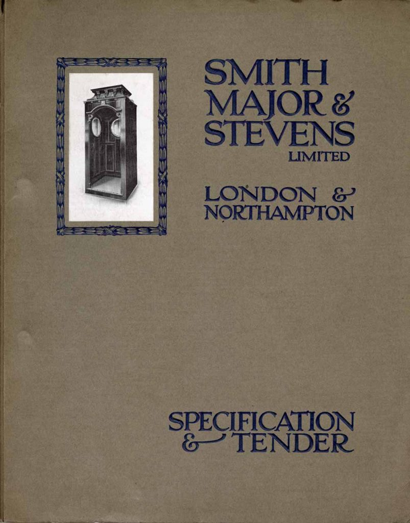
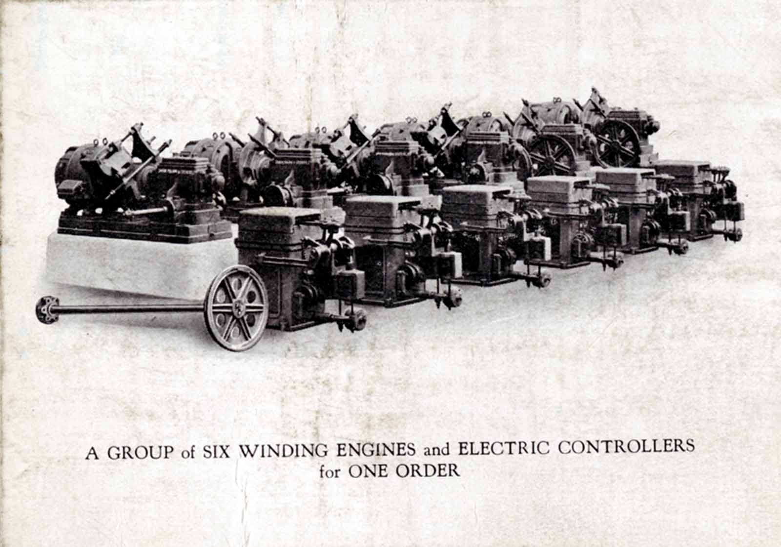
The specification and tender were presented in a branded folder that featured a picture of a passenger lift car on the front cover and a picture titled “A group of six winding engines and electric controllers for one order” on the rear cover (Figures 1 and 2).[1] The folder’s contents included a cover letter addressed to E. Davies, Engineer, Atlas Works (Shewsbury), a detailed specification and tender, a copy of a catalog that described the company’s new vertical type of controller (which will be the subject of a future article) and a one-page list of “a few installations.” The letter noted that the enquiry from the Atlas Works had been received on 2 March; Smith, Major and Stevens replied on 6 March with a “detailed Specification and Tender for an electrically operated Goods Lift.” Their letter also noted that they would be “pleased to provide (Atlas) with any necessary drawings to enable preparation work to be proceeded with.”The speed of the response to Davies’ enquiry was made possible by organization of the required materials.
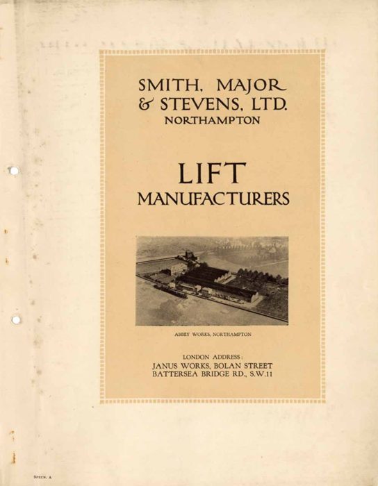
Each sheet of the specification and tender was identified (at the bottom) by an abbreviation for the word specification and a letter, thus the first sheet (a secondary cover sheet) was identified as “Specn. A” (Figure 3). Sheet B indicated that the specification and tender was for an electric lift, noting that it concerned a goods lift for use at the Atlas Works. Sheet C, labeled “Quantitative Specification,” was designed to be filled out (using a typewriter), and provided information on the machine type, load (in cwts.), speed (feet per minute), travel, levels served, well (type and size), control method, engine position, guides (cage and balance weight), cage (type, design, openings and size), gates and/or doors (landing, cage and size) electric locks, electric bells, electric light, electric switches, main switch and fuses, supply cabling, electric supply, ropes, enclosure and builder’s work (Figure 4). The data found on the sheet was both specific and general: While the well was listed as 5’6” by 5’6” and made of brick, only the car height was specified (as 6’6”), with an accompanying note that the width and depth was “to suit the well available.” Details asked for with regard to the electric supply included nature — AC or DC, and source — public or private. If alternating current was provided, the form also asked for the “no. of phases and periodicity.”
The Quantitative Specification sheet was followed by two sheets that addressed the actual tender (Specn. N & O). The tender sheets included the net cost of an electric goods lift, controlled by “full automatic push button gearing, included a wrought iron framed cage, buffer stops under the cage and balance weight, special ropes, electric locking gear, free insurance, and all as specified, delivered and fixed complete.” Features priced separately included switches, lights, gates and doors (Table One).
| £ | s. | |
| Electric Goods Lift | 479 | 10 |
| 1 Main Switch | 4 | 5 |
| 1 Switch in Motor Room | 4 | 5 |
| Electric Light | 3 | 15 |
| 2 Cage Gates | 19 | 10 |
| 2 Cage Gate Switches | 5 | 0 |
| 1 Landing Gate | 7 | 5 |
| 4 Pairs Double Doors | 80 | 0 |
| Total | 603 | 10 |
The estimated cost of ropes (four were included in the Quantitative Specification), at “4/-per ft run, extra on actual measured length fixed,” was not typed onto the form but had been entered by hand as “£574 less 5%.” Thus, the total estimated cost of the lift was £1,177 s.10. Only one alternate cost was listed: “If the guides for cage and balance weight are constructed of round polished steel, our extra price will be £32 s.10.”
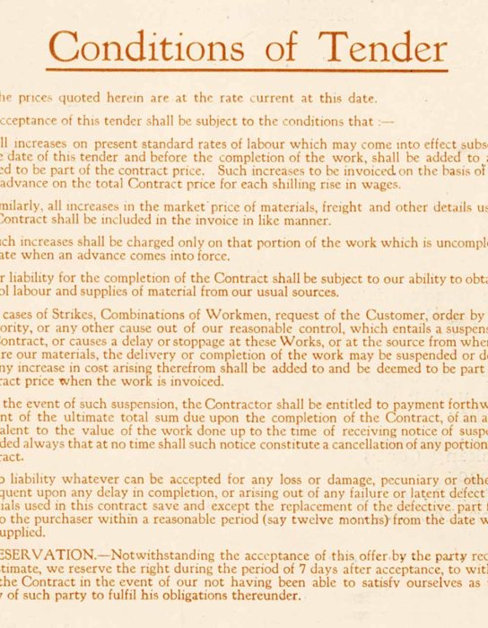
The reverse side of specification sheet N contained the “Conditions of Tender,” which addressed issues such as price increases, work stoppages and liability. The possibility of a work stoppage, due to “strikes, combinations of workmen, request of the customer, (or by) order by public authority,” hints at the question of the nature of the VT workforce during the 1920s.
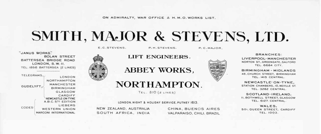
Interestingly, two differing attitudes toward this topic were addressed by two “seals” found on Smith, Major and Stevens’ letterhead (Figure 5). The letterhead featured the seals of the National Scheme for Disabled Men and the Engineering and Allied Employers National Federation. The former was a pioneering social initiative launched on September 15, 1919, designed to help disabled World War I veterans find employment. Companies who agreed to employ an approved percentage of disabled ex-service men were enrolled and granted the right to use the program’s “seal of honour.” The latter seal represented an alliance founded in 1896 designed to consolidate the bargaining power of engineering firms in their negotiations with labour unions and to address threats of strikes and work stoppages.
Specification sheet P provided information on the lift insurance automatically included with the purchase of a Smith, Major and Stevens machine:
“By arrangement with a leading insurance company, in virtue of their confidence in the reliability of our machines, we are enabled to include in our offer for the lift, without further charge, a policy to cover an indemnity against third party risk as well as against mechanical and electrical breakdown, for a period of twelve months from the date of the lift being handed over on completion.”
The policy provided:
“Against mechanical and electrical breakdown, an indemnity on the motor not exceeding (50 lb)
And on the controller and mechanical portions of lift not exceeding (200 lb)
Against third party risk an indemnity for death or injury to any one person in one accident not exceeding (1000 lb)
An indemnity for death or injury to two or more persons in any one accident not exceeding total (2000 lb)
Number of accidents covered for the one year’s period of insurance … Unlimited”
Lastly, Smith, Major and Stevens stated that they would be happy to “continue this coverage … on the expiration of the period at a nominal premium of £5 10s. per annum, and from this premium we can offer you a rebate of 15 percent in the absence of any claim.”
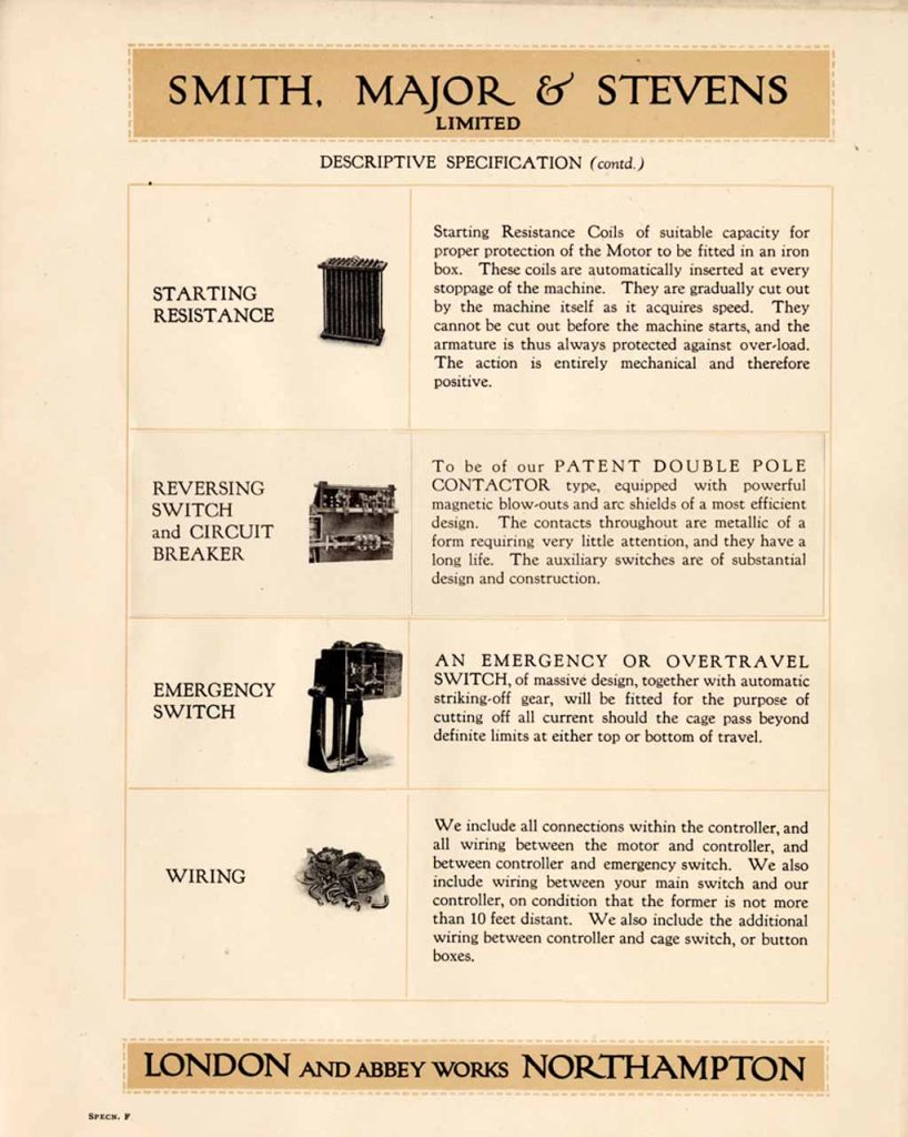
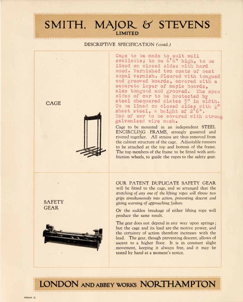
A detailed “Descriptive Specification” was provided on sheets D, E, F, G, H, K, L, M, Q and X, which was divided into three sections: Sheets D, E, F, G, H and Q provided information on standard lift components, sheets K and L provided general installation information, sheet X provided information on components that would be included with a lift installation “when desired,” and sheet M was left blank, which allowed for the provision of additional information (as needed). The list of standard lift components included the motor, safety coil, brake, gearing, adjustable coupling between armature shaft and worm shaft, bedplate, controller, starting resistance coils, reversing switch and circuit breaker, emergency switch, cage, safety gear, ropes, balance weights, cage guides and balance weight guides. The specification for each component included a written description and, in most cases, an illustration (Figure 6). For components where additional job-specific information was required, space was provided that allowed the information to be added to the sheet — additional information was provided in red type to distinguish it from standard details (Figure 7).
The components listed on sheet X, to be provided when desired, included:
- “Quick break switch: One switch of ample capacity will be provided as quoted, to be fixed in motor room (within 10 ft of controller) mounted in suitable case with improved Cut-outs. When desired a similar Switch and Cut-outs will be provided and fixed (at extra as quoted) at a point adjacent to Supply Co.’s meter.
- Main cabling: When desired, we will provide and fix the necessary run of cabling for connection from a main switch adjacent to Supply Co.’s meter within the building, to main switch in lift motor room. Our price will be as quoted and includes for the proper number of cables enclosed in seamless enamelled conduit.
- Electric light: When desired, we will provide and fix an electric light in the cage. Our price for this, complete with lamp, holder, shade, switch, flexible cable and hanging rose fixed at a point about halfway up the well, will be as quoted.
- Electric bells: When desired, we will provide and fix an electric bell in cage, complete with suitable indicator. The extra price as quoted includes the battery, swinging cable and a push on each of the landings served, as stated in the quantitative specification attached.
- Cage gate: When desired, we will provide and fit (at extra price as quoted) a light collapsible gate complete with top and bottom tracks, to such openings in cage as are stated in the quantitative specification attached.
- Cage gate switch: When desired, we will provide and fit to each of the above gates, an electric switch wired in the control circuit of lift, making it impossible to move the cage until the cage gate is closed. Our price will be as quoted.
- Landing gates: When desired, we will provide and fix to each of the openings in enclosure, which have been suitably prepared for its reception, a single collapsible gate of the top hung type, complete with top and bottom track and rollers, and fitted with spring latch, or alternatively prepared for our electric locks.”
Perhaps the most interesting piece of optional equipment was the cage gate switch, which was a safety designed to ensure that the lift could not operate if a cage door was open. By the 1920s, this was a common safety device that was often required by local codes and/or regulations; thus, its representation as an optional feature is surprising.
Perhaps the most interesting piece of optional equipment was the cage gate switch, which was a safety designed to ensure that the lift could not operate if a cage door was open.
The general installation information found on sheets K and L addressed over-travel, position of gearing, painting, guarantee, exclusions and terms of payment. Over-travel was:
“Automatically provided against in three distinct ways operating in the following order: first, by inclined planes operating a knock-off switch, or the auto gear on cage; secondly (should the first by chance fail), by the emergency switch cutting off current; thirdly, when either cage or balance weight touches the bottom, the lifting ropes slip on the hauling wheel, and the cage stops even though the motor continues to run.”
Work that was excluded from the specification and tender included the “preparation of well-hole, any cutting away or making good of brickwork, masonry, etc., excavation or concrete foundation for motor, overhead girders, stanchions or supports for girders, any enclosure or other builder’s work.” Smith, Major and Stevens also noted that they required “the provision, free of cost, of suitable scaffolding for our use during erection.”
Sheet M included additional information on the motor, lift control gear, electric locks and doors. The motor included in the specification was to be manufactured by either the Metropolitan Vickers Electrical Co. (Manchester), Lawrence Scott & Co. (Norwich) or the English Electrical Co. (Phoenix Works, Bradford). The primary specification for the lift control gear stated that it would be:
“Push button gear … of the full automatic type, the lift being fitted with an electrically operated floor selecting gear connected by suitable wiring to the push buttons in the cage and at the landing levels served. In the cage would be provided a switch box containing a number of buttons corresponding to the landing levels served, and arranged so that on pressing any of the buttons the lift would travel up or down as desired, automatically stopping when the required floor is reached. A stop button would be provided also in the cage enabling the lift to be stopped by the operator in case of emergency. At each of the landing levels would be fixed a call button, upon pressing which the lift would start, and come to rest automatically when the landing level is reached.”
Lastly, Smith, Major and Stevens noted that: “As desired we have included a provisional sum of £80 in the tender for the provision of four Double Moulmein (wooden) Teak Fireproof Doors and Framework, and we presume these doors will be prepared to receive our Electric Locking Gear.”
The final page of the specification was sheet X, which was titled “A Few Installations.” The installations were loosely grouped into five categories: government installations, office buildings, industrial buildings, ocean liners and overseas installations. These installations provide an insight into the variety of lift types provided by Smith, Major and Stevens and the breadth of their industry experience. Their government work included 173 lifts furnished to the British Admiralty for use on Super-Dreadnoughts. Their overseas work included installations in Australia, India, Singapore and South Africa. Future articles will explore these (and other) lift applications and installations.
Careful readers may have noticed that the Atlas Works specification and tender did not include sheets I, J, R, S, T, U, V and Z. Given the clarity of the organizational system employed by Smith, Major and Stevens, it may be reasonable to assume that these sheets existed and were designed for use in hydraulic lift specifications. Of course, we will have to wait until a specification and tender for a hydraulic lift is found to confirm this speculation. In the meantime, we have this as an example of British VT industry practice in the 1920s. While it provides insights into the business practices of one firm, its presence also prompts a question: Was this representative of an industry standard of practice? The recent discovery of a 1925 Estimate and Specification prepared by William Wadsworth & Sons allows for a comparison that will help answer this question. The Wadsworth document will be the subject of my next article.
References
[1] Smith, Major and Stevens, Ltd. Specification & Tender (1927). Note: All material for this article dervies from this source.
Get more of Elevator World. Sign up for our free e-newsletter.
