A Design Methodology of Rope Tension Meter Used for Lift Automatic Door Assembly
Sep 1, 2021

Potentially easy-to-use device could quickly be in production.
by Anup Balharpure and Rohit Nehe

This paper was first presented at the 11th Symposium on Lift & Escalator Technologies (liftsymposium.org).
Keywords: rope tension, load cell, lift automatic door, automatic door operator
The present work demonstrates a low-cost open-source design of a rope tension meter specifically designed for measuring rope tension of lift door assemblies. The potential use of such an easy-to-use, economical and handy unit could be in a door operator production plant and on installation sites for measuring rope tension.
The rope tension meter consists of a sensor unit and the embedded system equipped with a signal-conditioning circuit, digitization circuit, microcontroller and interactive display. The sensor unit is designed such that the load cell is mounted on a custom-designed mechanical structure. The sensor unit can clip onto a rope using an attached hand screw. While measuring the rope tension, the sensor unit clipped onto the rope gives an analog output signal proportional to the load applied on the load cell. The analog output signal of the load cell is fed to the microcontroller through the signal conditioning and digitization circuit, and the corresponding load value is displayed on a screen as per the desired units of the load. To evaluate whether the rope tension meter was working, tests were performed on an automatic door operator setup. In this test, the rope tension meter showed a proportional response for any changes in the tension and high repeatability in its results. To calibrate the rope tension meter signal against the rope tension in units of Newton (N), calibration tests were performed.

The study described in this document tries to fill in the gap in the literature regarding the development of rope tension meters used for measuring rope tension of lift automatic door assemblies. The design and the procedure discussed could be utilized by lift manufacturing and service companies for developing a portable and low-cost rope tension meter tool for factory or onsite use.
Introduction
The lift automatic door assembly is one of the major components of the lift. A typical lift automatic door mechanism consists of a car door assembly and a landing door assembly. In the lift door mechanism, the car door assembly is an active driving component, while the landing door assembly is a passive driven component, i.e., car doors are power-operated through drive and motor with the landing doors simply following the car door motion through a mechanical linkage. This mechanical tie consists of a vertical vane also known as a coupler skate (or a pair of vanes, depending on the type of doors) mounted on the car door assembly (see Figure 1-A) and a pair of rollers mounted on the landing door interlock. During the door opening and closing operation, the vanes are engaged with the landing door lock rollers resulting in a simultaneous movement of car and landing doors.[1]
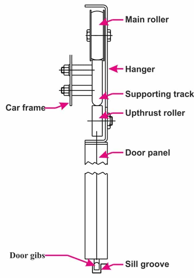
Figure 1-B shows the side view of door operator assembly excluding the interlocking mechanism, which typically is used to interlock the car and landing doors. In general, the door operator mechanism includes door hangers, door panels, pulleys, rope, hanger track, sill groove and door gibs. Each panel of horizontal sliding doors is hung on hangers — also called a carriage — and guided on a hanger track at the top and by a sill groove at the bottom, as shown in Figure 1-B.[1] During door operation (opening and closing motion), the door panels move in opposite directions in the case of center-opening mechanisms (further details about the types of door and roping system can be referred from reference source[1]). The linkage between the door panels is established through a simple roping system of two pulleys. The smooth movement of the door panels can be obtained by maintaining the required tension in the rope. Over time, due to wear and tear during normal usage, the rope tension needs to be re-adjusted. To reduce a breakdown due to door panel-related problems, periodic maintenance of its components and rope tension adjustment of the lift door mechanism is important.
Various types of analog and digital rope tension meters are available on the market, but these measurement tools are not specifically designed for lift door operator ropes. To adjust a rope’s tension, many engineers, onsite or in a production plant, estimate rope tension by hand/feel. Determination of rope tension by feel (pushing/pulling the rope by hand) is more of an art form than a learned skill[2] and is not an accurate method because rope tension will vary from person to person. To address this issue, present work demonstrates a low-cost open-source design of a rope tension meter specifically designed to measure rope tension of lift automatic door assemblies.
For this demonstration, we are using off-the-shelf components, such as a low-cost open-source Arduino Uno board as the processing unit, HX711 module as a signal conditioning unit, a Nextion 4.3-in. display and a customized sensor unit that consists of a mechanical structure and load cell. Further details about the rope tension meter calibration and its demonstration to measure the rope tension of a door operator mechanism is discussed in detail in subsequent sections.
Rope Tension Meter Design and Experimental Setup
The rope tension meter discussed in this paper is designed so it can be used as a portable and easy-to-operate service tool both onsite and during the door operator manufacturing process. In this section, details about rope tension meter design, load cell calibration setup, sensor unit calibration and lift automatic door operator test jig are discussed.
Rope tension meter design and its working principle
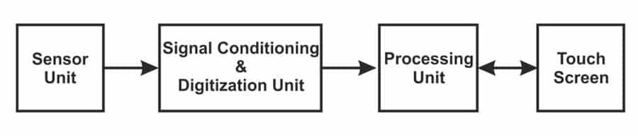
Figure 2 shows the block diagram of the rope tension meter discussed in this paper. It consists of a sensor unit, signal conditioning and digitization unit, a processing unit and a touch screen.
Sensor unit
The sensor unit consists of an LFT-25 Miniature Compression and Tension 50-kg Load Cell housed within the mechanical structure assembly. This customized sensor unit utilizes bridge-type sensors with strain gauge technology.[3]
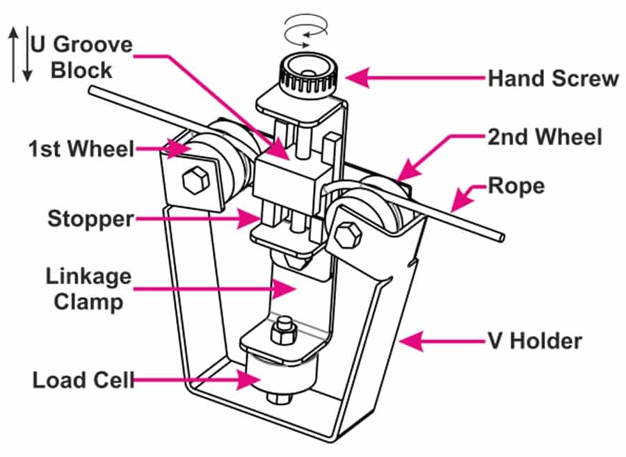
The sensor unit is designed such that the load cell is fitted within a custom mechanical structure. The main purpose of the mechanical structure is to provide housing for a load cell and to transform the tension from the rope to the load cell. The mechanical structure consists of two wheels, a U-groove block, a V-holder, a linkage clamp, a stopper and a hand screw. Figure 3 shows the CAD image of the rope tension meter designed and discussed in this paper. The first and second wheels discussed in Figure 3 act as guiding wheels, ensuring the correct placement of the rope within the sensor unit. The U-groove block works as a traversing clamping element. By using a hand screw, the U-groove block can be moved such that it can clamp the rope until the movement of the U-groove block is halted by the stopper. The subassembly of the U-groove block, stopper and hand screw is mounted on the linkage clamp, which facilitates the transfer of rope tension to the load cell.
Following is the procedure that describes the working of the sensor unit, i.e., the working of mechanical structure assembly and the load cell to measure the tension of the rope:
- Adjust the rope and the sensor unit such that the rope is placed within the groove of the first and second wheels.
- Once the rope is placed in the sensor unit, the U-groove clamp is moved through the hand screw such that the U-groove clamps the rope tightly until the movement of the U-groove clamp is stopped by the stopper.
- Due to the clamping of the rope by the U-groove clamp, the tension of the rope is transferred to the load cell through a linkage clamp.
- The resultant analog output voltage, which is given by the load cell proportional to rope tension, is fed to the electronic circuitry to process and provide the output data in the required format.
Signal conditioning unit
The HX711 amplifier and 24-bit analog-to-digital converter (ADC) module is used as a signal conditioning unit for the rope tension meter. It is based on Avia Semiconductor’s patented technology, specially designed for weighing scale and industrial control applications to interface directly with a bridge sensor. It has two channels, A and B, with built-in low-noise programmable gain amplifier (PGA) and a selectable gain of 64 and 128 for channel-A and constant gain of 32 for channel-B.[4] It is low-cost and easily available on the open market. This module gives output in a serial format with two-wire serial communication.
Processing unit
Arduino Uno is an open-source and easily available development board. It is used as a processing unit in the demonstration work. For further details of the board, see the reference.[5]
Touch screen
Nextion make model NX4827K043_011R, a 4.3-in. resistive touch screen,[6] is used as the human-machine touch-based interface for the rope tension meter described in this paper. The NX4827K043_011R display is very easy to use and available on the market and is serially interfaced with the processing unit of the rope tension meter. The output data processed by the processing unit is displayed on the custom-made GUI of the Nextion make 4.3-in. display.
Load cell calibration setup
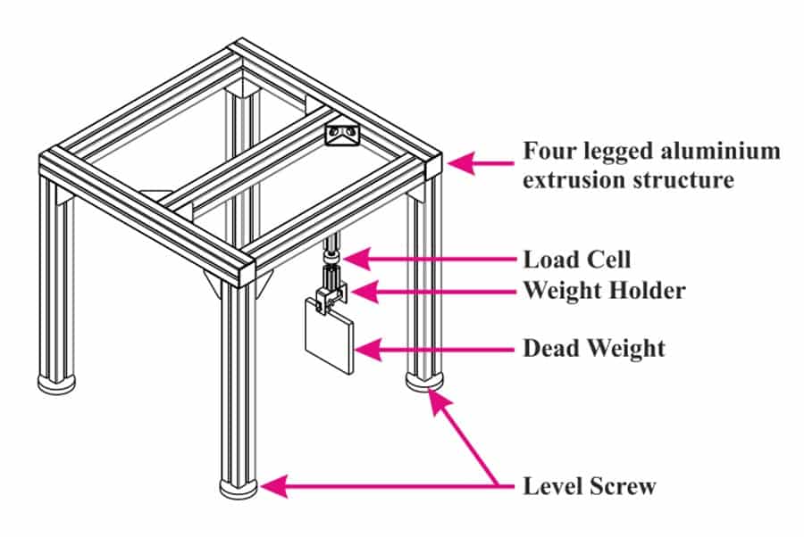
Figure 4 depicts the load cell calibration setup used to study the characteristics of the load cell. The setup consists of a four-legged aluminium extrusion structure with level screws, built in such a way that the load cell is fixed on one of the top members of the structure. The load cell is fitted with a holder that can hold multiple calibrated weights.
To calibrate the response of the load cell against various known weights, calibration experiments are performed. The dead weights used for calibration experiments are of F1 precision class and are calibrated in the National Accreditation Board for Testing and Calibration Laboratories, India (NABL) accredited laboratory. During the calibration experiments, the load cell is provided by ~5-V excitation from the HX711 module. To calibrate the load cell, the load cell holder is fixed with a known weight and the proportional response, in terms of the analog output voltage, is measured and processed by the processing unit. The calibration experiment is performed such that the load cell response is measured for various weights resulting in a lookup table data of load cell output (analog voltage signal) versus weights in desired units, N or kgf. The results of load cell calibration experiments will be discussed later this document.
Sensor unit calibration setup
A sensor unit, as described earlier, consists of a load cell mounted within a mechanical structure assembly. The construction of the sensor unit is designed such that the tension or the load to be measured is transferred to the load cell via a linkage clamp — unlike the loading of the load cell as previously described wherein the load cell is directly loaded with weights without any intermediate member attenuating the loading force. To calibrate the sensor unit analog output data against the weight in the desired unit (N or kgf), the sensor unit calibration experiments are performed using the setup highlighted in Figure 5.
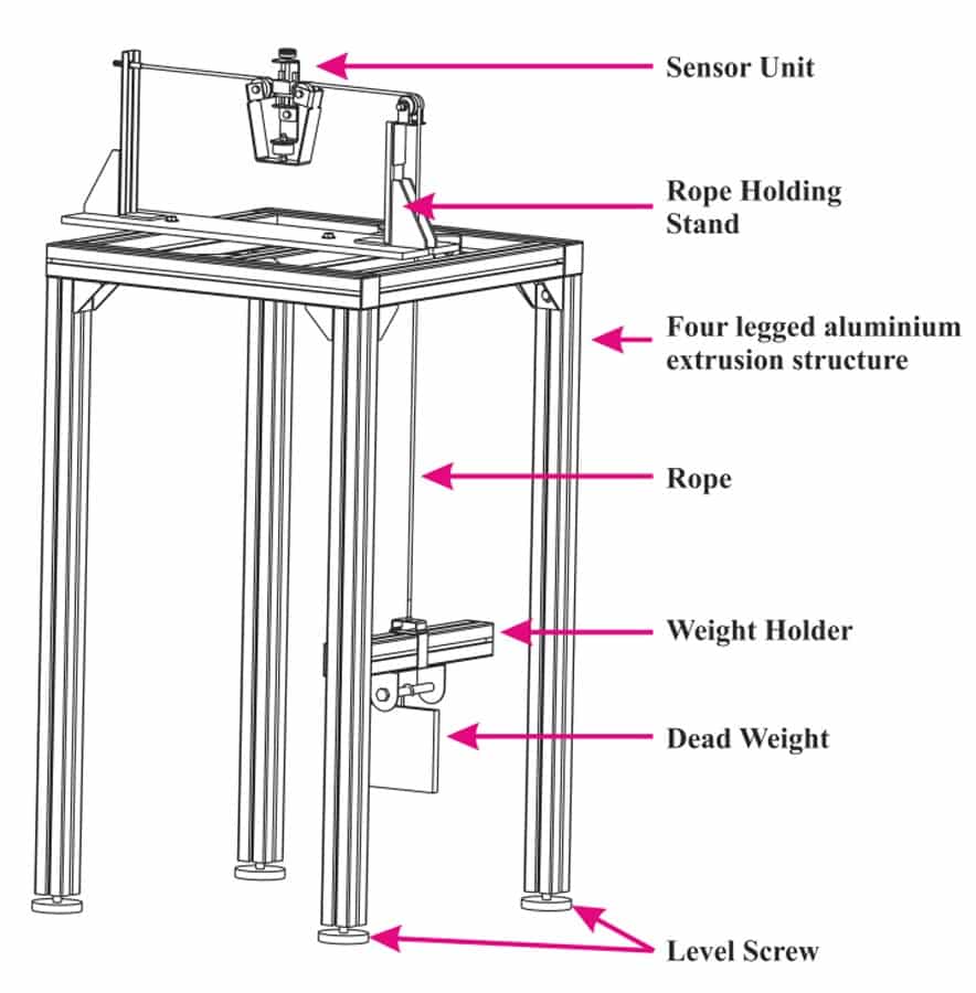
Sensor unit calibration setup consists of the four-legged mounting table made from aluminium extrusion members, a rope-holding stand with a rope-guiding pulley at one end, a weight holder to hang the dead weights, the rope and the calibrated dead weights. The rope used for the calibration setup is the same as the rope used for lift automatic door operator assemblies (rope material: SS wire rope; material grade: SS304; OD: 3mm; construction: crossley pattern with 7 cores; minimum braking force: 1570 (N/mm2)). The dead weights used in calibrations setup are the same as the dead weights used in the previous section.
To calibrate the sensor unit on calibration setup, rope is fixed at one end of the rope-holding stand and another end is connected to the weight holder, as shown in Figure 5. The sensor unit is clipped on a rope by using the hand screw as previously explained. The rope tension is altered by adding various calibrated dead weights on the weight holder. The raw ADC count to be recorded is sent to the PC using the Arduino board.
Lift automatic door operator test jig
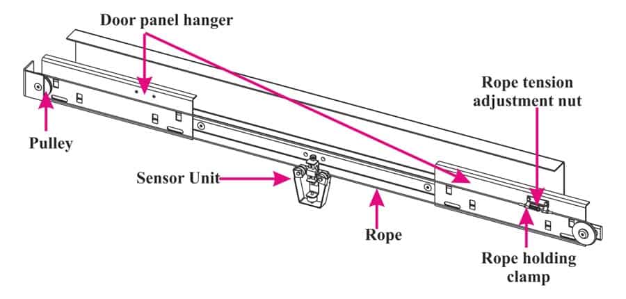
Figure 6 highlights a particular type of lift automatic door operator mechanism used in the experimental setup described in this paper to demonstrate the working of rope tension meter (sensor unit and electronic circuitry). This mechanism involves door panel hangers, ropes, pulleys and tracks for the movement of the door panel hangers. To adjust the rope tension, a rope tension adjustment nut is provided. By turning the nut clockwise or anticlockwise, rope tension can be increased or decreased.
The rope tension meter described earlier is calibrated for various nut positions, i.e., for various rope-tension settings of the door operator mechanism. This experiment provides a lookup table of rope tension meter analog output data versus multiple rope tension nut positions. By utilizing the data sets obtained from experimental setups shown in Figures 4 and 5, the rope tension meter is calibrated in the desired units (N or kgf) for multiple rope tension nut settings.
(Note: Figure 6 depicts the lift automatic car door operator assembly. For simplicity, some parts of the assembly, such as the motor, belt and coupler skate, are not shown.)
Results and Discussion
In this section, results of the load cell calibration setup, sensor unit calibration setup and rope tension meter testing on lift automatic door test jig are discussed.
Load cell calibration results
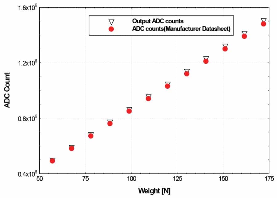
Load cell calibration experiments are performed using the setup described previously and the results are highlighted in Figure 7. To calibrate the load cell, calibrated weights of ~9.81 N are gradually added and corresponding results in terms of ADC counts are recorded. The readings are recorded for the weights in the range of 50 N to 180 N. To obtain statistically averaged data, each data point highlighted in Figure 7 is calculated by averaging the data over the sampling window of 50 data points.
In Figure 7, the x-axis represents the weights (N) and the y-axis represents ADC counts. The plot shows two data sets: one is the load cell output ADC count recorded from the experimental work, which is shown by black color marker, and the other is the load cell output data obtained from the datasheet[3] supplied by the manufacturer, shown in red color. This experiment is carried out to verify the linearity of the load cell as mentioned in the datasheet. As seen in the plot highlighted in Figure 7, the experimental readings follow the expected linear behavior with the highest deviation of less than 1.5%, compared to the data set provided by the manufacturer.
Sensor unit calibration results
Figure 8 shows the experimental calibration data of the sensor unit. The load cell used in the sensor unit is not directly loaded with the rope tension; instead, it is loaded with the help of a linkage clamp. The design of the sensor unit (mechanical structure and linkage clamp) happens to be such that it transfers the attenuated rope tension to the load cell. In the case of a sensor unit, the load cell needs to be recalibrated to account for the attenuated loading effect induced by mechanical structure on a load cell.
In Figure 8, the x-axis represents the rope tension (N) and the y-axis represents output ADC count. To obtain statistically averaged data, each data point highlighted in Figure 8 is calculated by averaging the data over the sampling window of 50 data points. The plot shows the sensor output in terms of ADC counts in red circles corresponding to calibrated weights in the range of 120 N to 320 N.
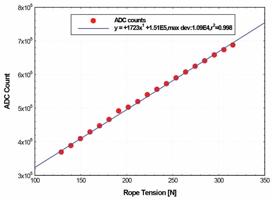
The data highlighted in Figure 8 show the linear response of the sensor unit similar to the linear response trend seen in Figure 7. However, as expected, due to attenuation effect, the response of the sensor unit compared to the bare load cell response (see Figure 7) corresponding to the same load is of lower value. For example, when the load cell is directly loaded with 150 N then the output is ~13 x 105 (1321328) ADC counts. When the load cell is indirectly loaded with the help of linkage clamp and mechanical structure in the sensor unit, the output decreases such that ADC counts recorded are ~4 x 10⁵ (408777). Such lower bound values of the sensor unit highlight the mechanical structure cause attenuation effect on a load cell.
Demonstration of rope tension meter
To evaluate and demonstrate the rope tension meter working (sensor unit and electronic circuitry), tests were performed on a lift automatic door operator setup. As discussed previously, one of the subassemblies of the automatic door operator setup consists of a roping system (roping and pulley system) to drive both the door panels. During the experiments, the rope tension of the roping system was varied by adjusting the tension nut at various positions. Note, the tension adjustment nut position is the distance between the rope holding clamp and the nut itself. To vary the rope tension, the rope tension adjustment nut is rotated manually and its position from the rope holding clamp is measured using a vernier scale.
Figure 9 shows the results of the experiments discussed in this section. In Figure 9, rope tension meter output in the units of ADC count is represented on the y-axis, while the tension adjustment nut position is shown on the x-axis. The experiment wherein the rope adjustment nut position was varied in the range 39 mm to 36.5 mm and the corresponding rope tension meter response was measured and is defined as test 1. To test the repeatability of results, such experiments were conducted five times and the corresponding data sets are labeled as TEST 1 to TEST 5 (Figure 9).
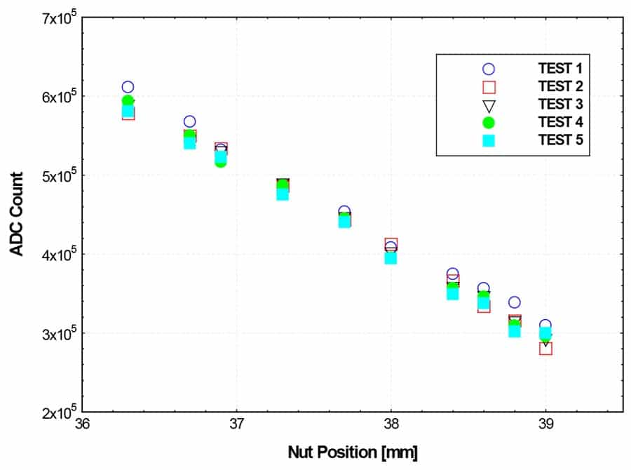
From Figure 9, it is observed that for the same nut position, the rope tension meter always showed repeatable results when the multiple tests were performed, i.e., TEST 1 to TEST 5. The repeatability result of the rope tension meter is seen for all the nut positions, i.e., from 39 mm to 36.5 mm. Thus, this result confirms the repeatable behavior of the rope tension meter discussed in this paper.
Another observation from Figure 9 to be discussed is the trend of increasing ADC counts as we change the nut position from 39 mm to 36.5 mm. The rope tension meter shows a higher tension value as we tighten the rope using a rope tension adjustment nut. This trend of results demonstrates the correct working of the rope tension meter designed in this paper.
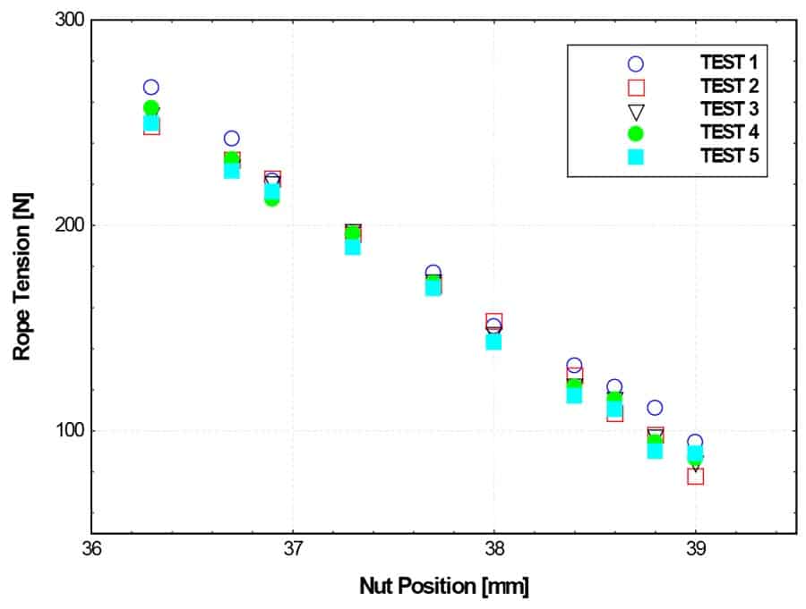
Figure 9 shows the rope tension meter output in the units of ADC counts. To convert the rope tension meter output from the units of ADC count to Newton (N), the calibration data set highlighted in Figure 8 is utilized (the linear fit equation). The resultant data set of rope tension meter output in the units of Newton (N) against the nut position is highlighted in Figure 10. Thus, this demonstrates the basic working and data reduction procedure of the rope tension meter designed and discussed in this paper.
Conclusion
A rope tension meter design methodology was explored in this paper. The rope tension meter as discussed is specifically designed for ropes used in lift automatic door mechanisms. The load cell used in the rope tension meter sensor unit design is based on strain gauge technology. To calibrate the load cell and the sensor unit, calibration experiments were performed. The calibration experiments result highlighted the linear and repeatable response of the load cell used in the rope tension meter. To demonstrate the working of the rope tension meter, experiments were conducted on a lift automatic door mechanism setup. The results from these experiments exhibit and confirm the repeatability and easy-to-use operation of a rope tension meter for checking the rope tension of a door mechanism roping system. The instrument also exhibits robustness in measuring data such that repeatable results were obtained at multiple positions of door operator roping system.
Acknowledgement
The authors are thankful to Samadhan Kadam (application engineer, Creestaa Elevator (India) Pvt. Ltd.), Baba Patil (research and development engineer, Creestaa Elevator (India) Pvt. Ltd) and Pratik Patil (design engineer, Rewale Engineering Pvt. Ltd.) for support for this work.
References
[1] L. Janovsky, “Elevator Mechanical Design (Third Edition).” Elevator World, Inc., U.S. (1999)
[2] Michael A., V. Dohre and T. Cecere, “Door Operators.” Educational Focus, ELEVATOR WORLD (2003)
[3] LFT-25-50 kg load cell details, en.ligentcn.com/a/chanpinzhanshi/zuqiuqicai/48.html (accessed 7 June 2020)
[4] HX711 module datasheet, cdn.sparkfun.com/assets/b/f/5/a/e/hx711F_EN.pdf (accessed 07 June 2020)
[5] Arduino Uno details, store.arduino.cc/usa/arduino-uno-rev3 (accessed 07 June 2020)
[6] Nextion make model-NX4827K043_011R details, nextion.tech/datasheets/nx4827k043/ (accessed 07 June 2020)
[7] C. Slattery and M. Nie, “A Reference Design for High-Performance, Low-Cost Weigh Scales.” Analog Dialogue, Vol. 39, No. 12, 1-6 (2005).
Rohit Nehe is head of the electrical and electronics department at Creestaa Elevators (India) Pvt. Ltd. He obtained his M.S. degree in mechanical and aerospace engineering in 2008 from Syracuse University, New York. He obtained his PhD in mechanical engineering in 2013 from Michigan State University, East Lansing, Michigan. He has a strong research and academic background in developing diagnostic instruments involving interdisciplinary engineering fields. His current activity at Creestaa Elevators involves research and product development in vertical-transportation systems.
Get more of Elevator World. Sign up for our free e-newsletter.

")


