A Load & Temperature Compensation Method for Green Hydraulic Lifts by Means of Inverters
Feb 1, 2013

This paper was presented at Elevcon USA 2012, the International Congress on Vertical Transportation Technologies and first published in IAEE book Elevator Technology 19, edited by A. Lustig. It is a reprint with permission from the International Association of Elevator Engineers IAEE. This paper is an exact reprint and has not been edited by ELEVATOR WORLD.
Key Words: Hydraulic lift, inverter, load-compensation, energy-efficiency
Abstract
Use of inverters in hydraulic lifts has decreased energy consumption, allowed smaller motor sizes and provided good ride performance for heavily used lifts. Though the general trend in the lift industry is towards lifts with lower energy requirement, use of hydraulic lifts with inverter has not found enough appeal yet. This is because of the fact that existing solutions are generally more demanding, rather costly and maintenance requires high level of expertise. A better solution that is compact, simpler to implement and inexpensive to compete with advantages of the conventional hydraulic lift system is necessary to make energy efficient solutions attractive.
When inverters are used with hydraulic power units, it is important to have accurate speed regulation regardless of load and temperature variations. Screw pumps are extensively used for hydraulic lift power units. Amount of leakage of screw pumps largely vary with the oil temperature and car load (pressure). With the use of an inverter the pump outputs just enough flow for instantaneous speed requirement. When pump leakage increases due to higher load and/or oil temperature, the car speed decreases which results in longer travel time and uncomfortable ride. Therefore, pump flow should be regulated according to the load and oil temperature to assure targeted speed and good ride-quality.
In this paper, economic-efficiency of hydraulic lifts is underlined and a new sensor-less load compensation solution is introduced to assure targeted speed under all load conditions. The solution basically consists of an inexpensive control valve and inverter with a sophisticated hydraulic software module. The new solution does not require interfaces between the control valve and the inverter such as pressure/load sensor, flow meter or electronic boards etc, works with open loop control and provides accurate speed regulation regardless of the load condition. The solution also provides an extra energy saving mode, where speed of the lift is varied according to the load condition by assuring the minimum travel time. All these advantages not only make the solution an energy efficient one but also an economically-efficient one as well. The paper gives the details of the idea used and features implemented in the development of the control valve and the advanced inverter software.
1. Introduction
Global warming and environmental pollution concerns are the driving forces that persuade manufacturers to produce energy efficient products. As a result of that optimum utilization of energy at lift systems has also become one of the main issues in the lift sector. The most effective development in this area is the use of an inverter with the Permanent Magnet Synchronization machine (PMS) to control lift speed. The development is also called as “the new or the latest technology” and reduced operational energy consumption considerably. Noticeable reduction in size and weight of PMS machines and their unique dynamic features also enabled engineers to construct Machine Room-Less lifts (MRL). With the introduction of MRLs it has been possible for traction lifts to be installed in low-rise buildings. Focussing on the energy consumption issue and using it as a marketing tool, MRL installations have managed to obtain an increasing trend in the market. As a result of that hydraulic lift installations are said to be reduced up to 40% globally.
“The new technology“has been reflected like it provides always the most energy efficient solution, perfectly suits every installation and energy can be always regenerated and dumped into the grid. However, the mentioned benefits of the existing “new technology” are not remarkable and mostly lead to higher energy consumption when it is used for low-usage lifts (Almeida, 2010) (approx. 80% of lift installations are in this category) where, the investment for the new technology may never be gained back during the life-time of the lift (Celik, 2009). This is because of the fact that the inverter and its peripheral devices are costly and require energy to be active even when the lift is at stand-by (Nipkow, 2005).
On the other hand, it is expected that future developments in the drive technology, like matrix converters, would drastically reduce or eliminate stand-by energy consumption and competition in the market will obviously lower inverter prices. In this respect, suitable solutions that are simple, inexpensive, easy to maintain, offer high compatibility and have low stand-by consumption are expected to find wide applications in coming years.
2. Application Of Inverter Drive On Hydraulic Lifts
Hydraulic lifts had been largely utilized in low-rise buildings. Reasons for the preference of hydraulic lifts are because of their unbeatable properties such as break-down free operation time, low initial cost, easy and cost effective installation and high ride quality. Hydraulic lifts also have the best records in safety, when it comes to rescue operations due to entrapments and natural disasters like earthquakes. They are also well known for their comparatively low servicing costs.
Having a more challenging market, hydraulic lift manufacturers have also given the first priority to energy saving factors in their designs. Energy-efficient power units that employ an inverter drive, so called the new-generation power units, have been introduced to the market long ago. However, utilization of the new generation power units has not found sufficient appeal yet. This is because while concentrating on the marketing issue to have the state of the art solutions, advantageous properties of hydraulic lifts have been ignored in many cases. By doing so practical, reliable and safety ingredients of hydraulic lift have been left instead, more demanding, impractical and expensive solutions have been introduced.
Having failed to address the main objectives of new-generation power units properly, solutions either became so primitive or rather complicated and costly. In many cases a conventional power unit with the addition of the inverter drive is presented as the state of the art. In fact, simply adding an inverter does not necessarily lead to energy savings. This is because during speed transitions (by-pass, acceleration, deceleration and levelling stages) nearly full pump flow rate are used and oil is by-passed to the tank, which increases energy consumption and generates considerable heat (Brunelli, 2011). Moreover, employing the inverter without justifying its 95% efficiency would only increase energy bills.
Alternatively there exist more demanding and costly solutions (Sedrak, 1999), which besides the inverter, need additional components like pressure and temperature sensors, flow meter, encoder, electronic control card etc. In these solutions mostly the inverter is used both in up and down directions with the help of exclusive inverter software. Application of such systems, no matter how good ride quality they give and how little they vary the oil temperature, are in general away from meeting the real market needs; unnecessarily extended pay-off time (beyond the renovation period), difficulty in finding competent technicians and increased servicing needs are some to pronounce.
3. Requirements From New Generation Control Valves
It is important to comprehend fully the requirements from the new generation control valve to meet the market expectations. These are:-
High usage:
to reduce stand-by energy consumption and obtain maximum benefit. Actually, so called green lift controllers include a sleeping mode, in which cooling fans are switched off after a certain rest time. For a longer rest-time the inverter could also be switched off however, in this case, deterioration of life-cycle duration of the inverter should be justified. In fact, a well designed inverter together with a green lift controller could last approximately 20 years though the inverter is switched off after a rest-time of 20 minutes for a lift having 100cycles/day. This could also reduce stand-by consumption up to 50 per cent.
Low cost:
to have reasonably short pay-off period and to meet market expectations. At present, inverter, control valve and sensoric systems keep the price of the new-generation hydraulic solution high. Particularly inverters are having 2 to 4 times higher prices than the conventional control valves. Therefore, a suitable solution should justify the use of an inverter with an inexpensive control valve and a simplified system design.
Minimum number of interfaces/components:
to assure simplicity, reliability, easy maintenance, low cost and also to eliminate the need for highly-qualified technical personal.
High compatibility:
to be fitted easily on all existing lift controllers and power packs in order to respond renovation needs.
Exclusive software:
to assure ease of use, safety, good ride-quality and low energy consumption.
An exclusive inverter software is required for the best performance of the new-generation valve. Apart from standard travel control routines (closed or open loop) and additional functions for good ride-quality, the software should include some compensation procedures to eliminate pump performance variations upon car load and oil temperature changes.
4. Blain EV4 New Generation Control Valve
There can be many ways to engage a control valve with an inverter to obtain a new-generation valve. The most important question is how to satisfy inexpensive and simple solution with good ride quality. Figure 1(a) shows some new-generation applications. Here, the closed-loop control solutions with electronic valves (requires a flow meter and an electronic card) or electro-mechanical valves (requires a submersible encoder and interface electronics) increase the cost of the system considerably. Simplicity of the system may be further disturbed with the existence of pressure or/and temperature sensors. In terms of energy-efficiency and initial investment, application of such systems can only be justified for very high-usage lifts (over 700 cycles/day).
Knowing the market needs and evaluating truly necessary requirements from the new generation power unit, Blain Hydraulics developed EV4, the new-generation control valve, which satisfies the aforementioned requirements as shown in Figure 1(b). Blain’s EV4 is a simplified version of Blain’s EV100 electro-mechanical valve, which inherently offers the same advantageous properties of electro-mechanical valves. It was designed to employ a Yaskawa inverter for up travel whereas down travel was managed by electro-mechanical means. EV4 has no interfaces with its peripheral devices and does not require sensoric for load compensation. Since up travel is controlled by the Yaskawa inverter, up solenoids and adjustments were removed from the valve and by-pass transition stage was cancelled, which simplified both the valve and the system set-up considerably. To lower the initial cost and simplify the system requirements further, superior open-loop control of Yaskawa inverter has been implemented. Thus, the need for a costly submersible encoder was eliminated. The real supremacy of the system comes from the exclusive inverter software, which eases the use of the system and provides excellent travel characteristics. The software was designed to sense the load condition to allow necessary compensation for the motor output. The software is also intelligent enough to modify transition times, when necessary, to assure good ride quality. Moreover, Yaskawa inverter can be optionally used for the down travel to control down speed and to improve ride-quality without needing any modification on the EV4 valve. In order to allow accurate load compensation and to account for the effects of oil temperature variation an inexpensive temperature sensor was also included in the system. The complete solution is inexpensive and can be easily applied to all hydraulic lifts, basically by adding EV4 valve and Yaskawa inverter to the existing system. Optionally, the car may be run either at a constant speed mode, where the lift speed is kept constant, or at an energy saving mode (Maximum speed mode), where the speed of the car is lowered according to the load in the car (Celik, 2008). The energy saving mode may allow lower motor sizes to be employed and may lead to lower energy consumption.
In addition, EV4 valve contains Blain Hydraulics’ latest development of GREEN 60 solenoid coils, which reduces energy consumption and increases the efficiency of the valve, and offers supply voltage flexibility to the user.
5. Application Of The Method
The new-generation EV4 valve is an electro-mechanical type and it was designed to allow inverter to take control of the complete speed regulation of the up travel. In this way the entire ride quality of the travel is assured by supplying only the necessary flow rate to the valve by regulating the motor speed by means of the Yaskawa inverter. As a result, less amount of energy is consumed during up travel, which increases the efficiency of the system and also reduces oil heating. Using the inverter also reduces motor starting current and the size of the electric energy meter.
On the other hand car load and oil temperature influence the leakage of screw pump drastically, which may cause speed and the total travel time of the lift to vary drastically. This is illustrated in Figure 2. In some cases, when oil temperature or/and car load is high, speed of the pump during levelling phase may not provide positive flow and lift stands still (zero speed) because of high pump leakage, which is illustrated by the dashed and the dotted line in Figure 2. Therefore, a suitable solution should allow for the compensation of pump leakage by adjusting the speed of the pump.

5.1. Initial Settings
In order propose a simplified and inexpensive solution Yaskawa V1000 inverter, which also contains computing, memory and monitoring modules, was utilized. An exclusive software of Yaskawa inverter provides the user with powerful menu options to ease the set-up process. At a very initial stage of the set-up process, the user selects the oil type from a list. As the selection is performed, necessary viscosity and temperature parameters are assigned to the registers.
In the second stage, the user inputs pump performance data according to the working pressure range of the lift. This data is easily obtainable from pump manufacturers. In this stage, full, levelling, inspection and secondary full speeds of the lift are also input in meter per seconds. Inverter then reads the current temperature (Temp2) and process oil and pump performance data to obtain motor speeds (reference frequencies) in Hz for the full, levelling, inspection and secondary full speeds. Additionally, temperature control gain (Gaintemp) and leakage reference frequencies for empty and loaded car pressures are also calculated. For simplicity these are given parametrically below:
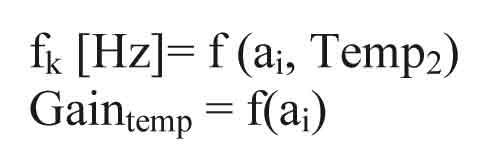
Where, fk and ai indicate calculated reference frequencies in Hz and input data respectively. The software also allows the user to input these variables manually in case the data is not available or the pump is old and worn.
5.2. Car Load and Oil Temperature Compensations
To sense the car load and to regulate the motor speed, the standard Yaskawa inverter software was re-designed to include some compensation procedures. The inverter can monitor at least one of the internal inverter parameters such as, output current, torque producing current or internal torque reference and also measures constantly the oil temperature by means of a temperature sensor. The monitored parameter, which is in most cases the internal torque, is then compared with a pre-set reference value to determine the load condition of the lift.
To obtain the reference values and the necessary control gains precisely the Yaskawa software is armed with teaching mode options as well as an operation mode. After setting the mode to “Teaching” initially a probe (teaching) run is performed with the empty car to read (also called as capture) and register the reference parameters. This is shown in Figure 3 where, capturing locations of full and levelling speed torque references, T2full and T2leveling respectively, are shown. Knowing T2full and T2leveling torque reference parameters and their corresponding speeds, other T2j torque references, for secondary full speed and inspection speed can be calculated with interpolation.

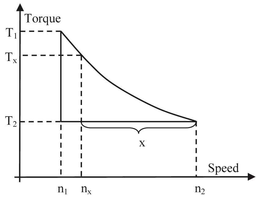
In Figure 4 derivation of lift speed with respect to empty and loaded car speeds is shown. Here, T1 and T2 are torque references that are captured at loaded and empty car probe runs respectively. From Figure 4, speed nx for a captured torque of Tx may be written as:-
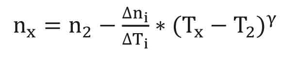
where, g : a constant, Tx : captured torque, T2 : torque reference captured at empty car probe run at a reference temperature Temp2, ![]() : difference in measured speeds,
: difference in measured speeds, ![]() : difference in captured torque references. Thus,
: difference in captured torque references. Thus,  , n2which is the amount of speed loss in %, can be simplified as:-
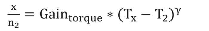
Thus, new reference frequency can be calculated as:-
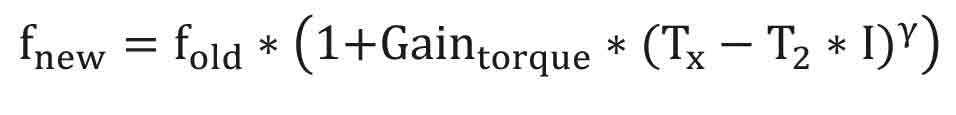

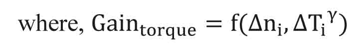
I is a special function that accounts for the variation of system resistance to flow as oil temperature varies. The second probe run at teaching mode is then repeated with the loaded car to obtain two other torque reference parameters, which are used for calculating the torque gain, Gaintorque in eqn (4). Similarly temperature calculation can be derived as below;

where, q : a constant, Tempx : captured oil temperature, Temp2 : oil temperature reference. The resulting equation for both load and oil temperature compensations may be given by:
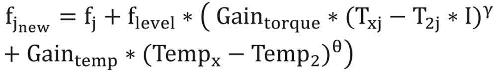
where, j indicates reference frequencies of full, secondary full, inspection or levelling speeds, flevel is the reference frequency of levelling speed. In eqn (8) initial speed frequency fj (i.e., ffull, fins, fsec etc) and reference frequency (T2full, T2ins, T2sec, etc) are modified depending on full speed selection. In the operation mode, T2 and Temp2 remain unchanged but Tx and Tempx are read (captured) for each run to re-calculate the reference frequencies under the actual load and oil temperature condition. In Figure 5, application of toque (load) and temperature compensations are shown.

5.3. Down Speed Compensation
When electro-mechanical valves are used for down travel, speed of the car increases with increasing oil temperature and system pressure (car load). This may result in jerky starts, rapid accelerations and hard decelerations, and jerky stops when working pressure range is large. The total travel time also changes due to varying speed and levelling durations. This is depicted in Figure 6.

Some of the new-generation valves can also be used for down travel. In that, while the pump/motor shaft is rotated in reverse direction by the hydraulic force of the oil column, the inverter controls the shaft rotation to regulate the speed of down travel. Here, the energy generated by the system is burned into a resistor, which prevents hydraulic oil getting heated further. However, such a solution complicates the control valve design and increases the system cost. It can only be justified with high-usage lifts by preventing the system from using an oil cooler as well as providing smoother ride-quality.
An inexpensive, simpler and easier way of controlling down travel ride-quality is introduced by the Yaskawa inverter software for low- and mid-usage lifts. In that, to control downward speed variations, controlled upward flow is produced when car load and oil temperature are excessive. This means, as the elevator coming down with its own weight and pushing the fluid through the valve into the tank, the pump can be used for giving upwards flow to regulate downward flow rate, i.e., the down speed.
Yaskawa inverter software offers down speed compensation as an option, which is applied in a similar way than up compensations. During down acceleration, the motor torque (Tx_down) is captured and a ramp is determined together with acceleration ramp times to provide smooth acceleration and constant speed. In Figure 6, car load compensations during down travel is also illustrated.
The dashed and dotted line shows uncontrolled down travel under loaded car or/and high oil temperature. The compensations optionally can only be applied during acceleration and deceleration stages, which is shown with the dashed line (Energy saving mode), or during the complete travel, which is shown with the solid line (Constant speed mode).
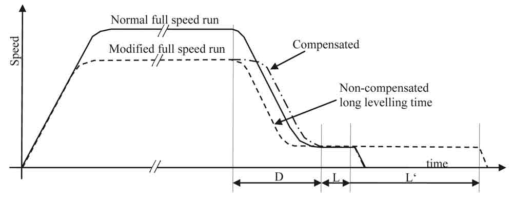
5.4. Deceleration Time Compensation
When the full speed is modified to a lower speed then levelling travel time, L may change considerably and create uncomfortable ride. This may happen at “constant speed mode” when for example, secondary full speed is selected instead of the normal full speed or at “maximum speed mode” (Energy saving mode), as lift speed changes with varying car load. In Figure 7, L and L’ show levelling durations of normal and modified travels that are illustrated with solid and dashed lines respectively. Here, levelling duration of L’ becomes rather long. In order to prevent this inconvenience and have a fixed levelling time, levelling duration and/or deceleration path of the modified travel is altered.
5.5. Travel Modes
At constant speed mode, lift speed is kept constant through the application of aforementioned car load and oil temperature compensations. At energy saving mode (also called maximum speed mode), speed of the lift is modified with respect to the car load. In that, car load and oil temperature compensations are applied normally for the levelling speed however, the full speed is limited by a pre-set limiting torque value, Tx_limit. This is shown in Figure 8. When the measured torque parameter during the run exceeds the limiting torque, Tx_limit (point (1) in Figure 8) then the reference frequency takes the value of output frequency until the end of the full-speed run. This is indicated with point (2) in Figure 8. In this way maximum allowable motor torque will not be exceeded when the car load is excessive. Conversely, the lift could travel at close to the maximum speed when the car load is low. In energy saving mode the deceleration path/time is also recalculated for each run to assure fix levelling time.

5.6. Additional Procedures for Better Ride Quality
In Figure 9 some of the additional properties of the Yaskawa inverter software are shown. These were introduced basically to assure high ride-quality. All procedures were designed with sufficient flexibility that could be utilized by different types of control valves. Some of these are:-

Start dwell: A special soft start procedure that is defined with the leakage frequency Q1 and ramp frequency Q2, and ramp times Q3 and Q4, which allows smooth and quick take-off.
Stop dwell: To assure short levelling duration, smooth and accurate stop, fully compensated Q6 dwell (leakage) frequency was implemented by the Yaskawa inverter software.
Levelling duration check: to provide better ride-quality previous levelling run duration is simultaneously compared with the current one and when necessary, corrective actions are taken.
Long waiting durations: The time between two consecutive runs is measured to assure smooth take-off after long waiting durations.
6. Conclusions
It is very likely that improvements on directives and legislations for energy-efficient product specifications will include lifts in the near future. It is also expected that complete or partial life-cycle assessment will be considered for energy-efficiency evaluation of lifts. Most of the new generation hydraulic power units are only suitable for high-usage lifts while they put up with high stand-by energy consumption, high initial cost, impractical and complicated set-up. With the present inverter technology, solutions that are simple, inexpensive, service-free and easy to install seem to meet market requirements much better and could acceptably be utilized on low-usage lifts.
Blain’s EV4 valve and Yaskawa’s V1000 inverter, using open-loop control and sensor-less load compensation with the use of special inverter software introduces an inexpensive and simplified solution for the new generation power units. The solution employs Yaskawa’s superior open-loop control routine together with specially designed procedures to assure excellent ride-quality. It can easily be applied to both up and down travels without increasing the complexity of the system by using either the constant speed mode or energy saving mode. In addition, it can be integrated with existing power units easily for renovation needs.
Acknowledgements
I would like to thank Yaskawa Europe GmbH, in particular Mr. Turgay Halimler, Mr. Philipp Kenneweg and Mrs. Karen Reiter for their support in developing the new inverter software.
References
Almeida A. T. (2010). Energy Efficiency of Elevators & Escalators, 4th European Lift Congress.
Brunelli, I. (2011). How it works: Hydraulic Lifts, Elevatori, Vol.2, pp.61.
Celik, K.F. (2009). Stand-by Energy Consumption on Low usage Lifts, Elevator World India, Vol.2, pp.58.
Celik, K.F. (2008). Design and Control of Electronic Elevator Valves, Elevator Technology 17, Proc. of Elevcon 2008, pp.34-45.
Nipkow, J (2005). Elektrizitätsverbrauch und Einspar-Potenziale bei Aufzügen, S.A.F.E.
Sedrak, D. (1999). Closed-Loop Electronic Valving and the Application of Variable Voltage Variable Frequency in Hydraulics, Elevator World, September 1999, pp.66.
Get more of Elevator World. Sign up for our free e-newsletter.


