A Special Kind of Heavy-Duty Elevator
Dec 5, 2023
Greta, Brumme and the ship lift Niederfinow north of Berlin
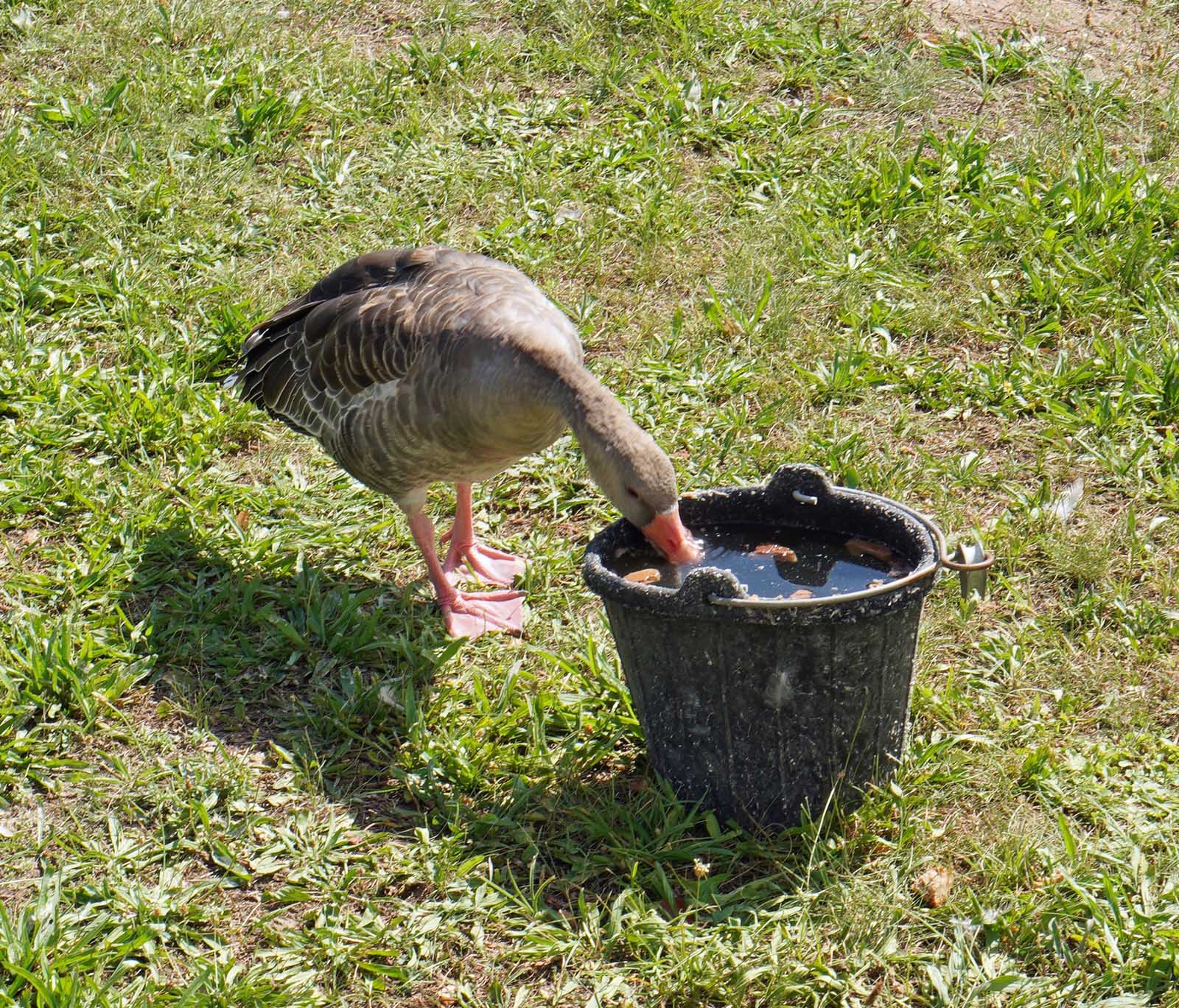
At the end of August, your author visited the Niederfinow ship lift on the Oder-Havel Canal, approximately 60 km northeast of Berlin, Germany. For safety reasons, life jackets were worn during the tour. In beautiful summer weather, the landmark could be seen towering high in the flat, sandy surrounding countryside from a distance. The plant site is guarded by, among other things, the goose Greta, which because of her broken wing has stayed in Germany (even during winter) for many years and is fed regularly.
Jörg Schumacher, head of local operations at the Oder-Havel Waterways and Shipping Authority (Wasserstraßen- und Schifffahrtsamt WSA), personally gave a 3-h tour of the new facility and the adjacent old facility. Since he was actively involved in the new construction from the very first minute of planning and had also previously been the operations manager of the old facility since 2001, he provided deep insights into the planning, construction phase and operation of both lifts. In the meantime, he has passed on his experience in locations as far away as China. At the Three Gorges Dam in the Yangtze River, the operation and maintenance of the ship lift are based on the German system.
History
At this location, there are now four generations of technical installations for overcoming the height differences in the canal.
Finow Canal of 1620
The Finow Canal was built between 1605 and 1620, and after destruction during the Thirty Years’ War, it was restored from 1743 onwards by decree of King Frederick II.
Lock Staircase 1914
The second generation was formed by a four-stage lock staircase with a lifting height of 4 x 9 m, which was in operation from 1914 to 1972. It is located directly north of the new lift, the unfilled remains of which are clearly visible from above. The lowest lock is located on the right and the third lock on the left with a distance of 200 m. At that time, too, a first lift was already being considered, but was then postponed due to the First World War. The ships were towed by eight electric locomotives, one of which is still preserved today.
Ship Lift 1934
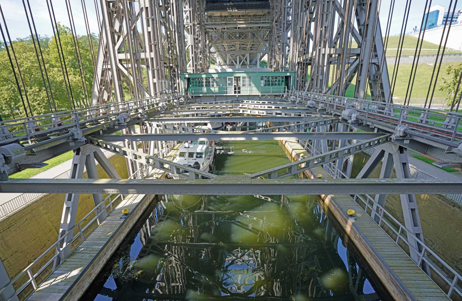
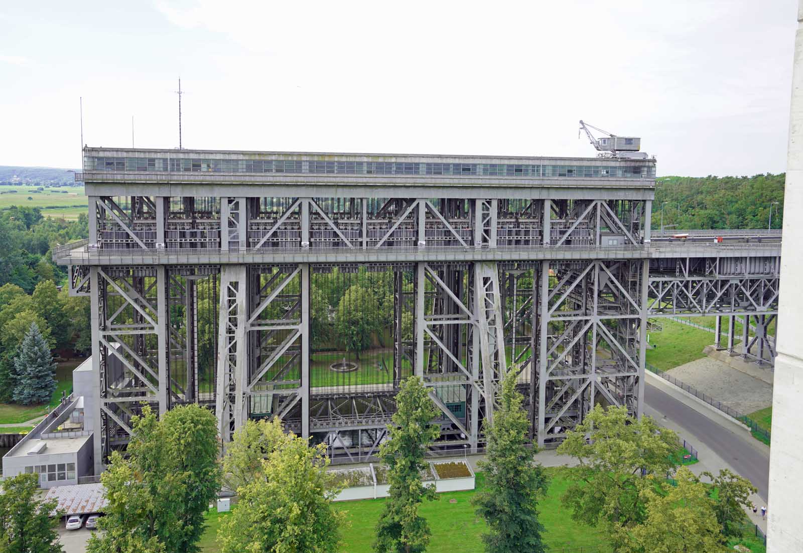
The listed industrial monument is 52-m high, the highest point being the crane. The width is 27 m, the length 94 m and the depth of the trough 8 m. The cost of the lift was 27.5 million Reichsmarks, comparable to EUR126.5 million today. Seventy-two thousand m³ of concrete, 18,000 t of steel and approximately 1.5 million rivets were used. It will remain in operation at least until the warranty on the new building has expired.
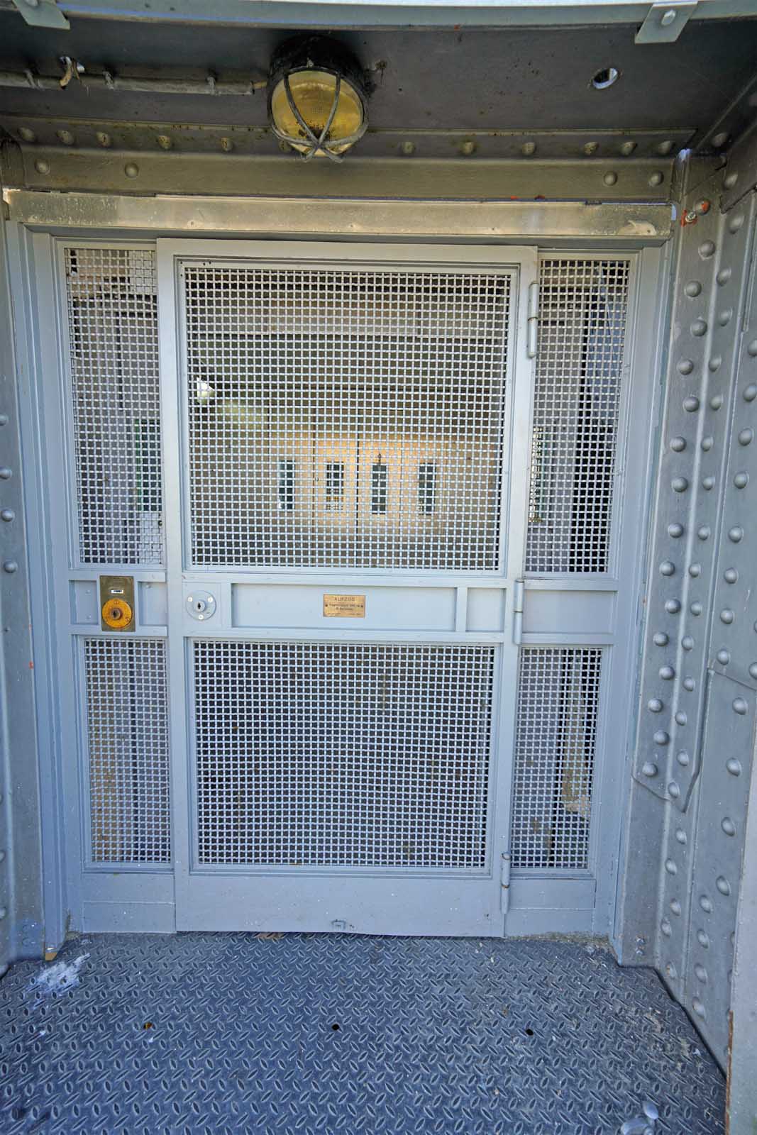
A Lödige elevator from 2000 transports employees and your author to the level of the visitors’ walkway or the rope sheave hall. The trough elevator machines are located directly above the trough. They are driven by four 55-kW DC electric motors that drive the hoists. One hoisting currently consumes electricity at a cost of about EUR12. The drive motor and four-stage gearbox sit directly on the drive shaft. Two acoustic signals and the trough starts to move.
Operations are carried out by hand and at the push of a button. In the engine house on the east side, the speed controller is controlled via resistors — just like on a vintage streetcar. The emergency stop switch bears the name “Brumme” (meaning hummer). The control panel still has its original labels in standard letters. Only the tachograph is new and digitally retrofitted by the company Endress + Hauser. The desk is covered with the original floor covering.
The lubricating oil pump supplies the continuous lubrication system. The scraped plain bearings are fed new oil every two years. They are designed as ring lubrication bearings. All machine parts are stored in the original as spare parts.
Between them, at the bottom of the floor, is the trough tub, which is around 90-m long and from which the filled trough, weighing around 4,300 t, is conveyed up and down.
The installation is attached to 256 ropes. Every eight ropes support a crossbeam with a counterweight package. One rope weighs 900 kg and has a diameter of 52 mm. In 1984, the ropes were completely renewed for the first time in 50 years. By February 2023, all the suspension ropes had been replaced again. The four compensating chains weigh a total of 90 t. The safety system consisting of a nut jaw column and screw can catch up to 2,400 t.
Planning, Construction and Operation of the New Plant
The new construction became necessary because of the increasing size of the ships needed to secure shipping traffic between Berlin, Germany, and the seaport of Szczecin, Poland. The lift is part of the E70 waterway from Rotterdam in the Netherlands to Klaipeda in Lithuania. Another technical problem was that the steel used in the old installation was becoming brittle.
Planning
Initial considerations were already made in the 1990s. A lift would require the least amount of water being exchanged between the Havel and Oder rivers. Since there was originally no water connection between these two rivers, the structure created an artificial watershed between the Baltic Sea and the North Sea.
The water level in the inflow usually only fluctuates by about half a meter. The water level above is 36-m higher. If a flood occurs, all moving parts above the waterline have to be removed. In the old plant, this required two days’ warning. In the new plant, the lower levels that flood are largely empty, as are all the basement levels; however, their heavy machine components remain.
Schumacher reports that he was involved in the planning as a Federal Waterways and Shipping Administration (WSV) representative. In 2001, the first preliminary draft was submitted for approval by the Beulke architectural office. Fundamental decisions such as the routing of the gates were made by the Federal Ministry of Construction. The planning approval procedure was carried out in 2004-2005. Construction then began with the laying of the foundation stone on March 23, 2009, with commissioning on October 4, 2022.
Of course, all applicable legal regulations and standards were taken into account during planning. For example, the pylons are subject to the high-rise building guidelines of the state of Brandenburg. Hydraulic engineering is largely covered by the office’s own administrative regulations. The passenger elevators installed comply with EN 81.
Construction Process
The four pylons and the cable pulley support columns were first raised evenly to a height of just under 55-m above ground level. Then, the two steel rope pulley supports, each weighing around 1,000 t, were placed on the sides between them and the rope pulleys inserted. The ropes were then laid, and the counterweights suspended. The trough was filled with sand; the 7,000 t of total weight then pulled the pylons, which had been pre-formed and inclined inward, into the vertical position. Finally, the canal bridge, which is approximately 66-m long, 22 m wide and 8 m high, was set up in front of the trough.
After the structure, with a width of just over 46 m and a length of 133 m, had been erected, mechanical engineering was started. All components were lifted in individual parts by crane, welded and braced.
The total cost of the lift was EUR520 million. The companies involved in the construction were Bilfinger Construction for the reinforced concrete construction, i.e., trough and supporting structure; DSD Brückenbau (bridge construction) for the steel construction, i.e., trough and canal bridge; Johann Bunte Bauunternehmung (construction) for the earthworks and special civil engineering, as well as SIEMAG TECBERG for the mechanical engineering, i.e., trough drive and safety. Approximately 1,200,000 m³ of earth was moved. Approximately 65,000 m3 of concrete and reinforced concrete, approximately 10,070 t of reinforcing steel and approximately 35,000 m² of sheet piling steel was used.
Nutzung
The lifting or lowering process takes about 20 min each. It is free of charge for users. In Germany, only the locks on the Moselle and the Kiel Canal are still subject to charges. Additional electricity is only required for the thyristors in winter. The heaters also do not run in summer. Both have an impact on operating costs.
Around 4,000 pleasure boats, 4,500 passenger ships and 6,000 to 8,000 cargo ships use the lift each year. The maximum ship length is 83.5 m at the old ship lift and 113 m at the new one. Among other things, steel and scrap are transported, but also large machine parts, e.g., for wind turbines. Following the rise in energy prices, hard coal is now also being hauled again. Containers are still lacking at present, but are expected to account for a larger share of the cargo in five years’ time.
Between 120,000 and 130,000 tourists visit the facilities every year. An information center was built especially for this purpose. Meanwhile, the care of the tourists has been handed over to the municipality, as the concept envisaged.
Maintenance Including Servicing and Initial Operating Experience
The plant is in ramp-up mode, during which interruptions are measured and plant components are adjusted. A complete monitoring of the plant is not planned. Many points can only be detected and evaluated by the human eye combined with experience.
The maintenance concept with service specifications is currently being developed on the basis of the first new and old operating experience and the suppliers’ specifications. It already contains around 1,000 topics broken down into the individual components. During the warranty period of five years, this work will be carried out by the consortium. The company’s own personnel are currently being sought and will then be trained to take over work partially at a yet-to-be determined date.
The WSV conducts an inspection every year. Every three years, there is a small check. Every six years, there is a full structural examination. This extends over 1.5 years and is carried out partly during ongoing operation, but also requires some shutdowns.
Some components were already defective, resulting in three standstills of six and nine days and four weeks. As the old plant runs in parallel, this has not yet led to any interruptions in the operation of the waterway as a whole. A great many components are currently stored as spare parts. Early this summer, they reached a spare parts inventory of 98%.
Operation of the New Plant
It is a vertical lift with counterbalance that works according to Archimedes’ principle of 236 BC: The weight of the trough remains the same with ship in it, as this always displaces its own mass of water.
Structures and Therein Moving Parts
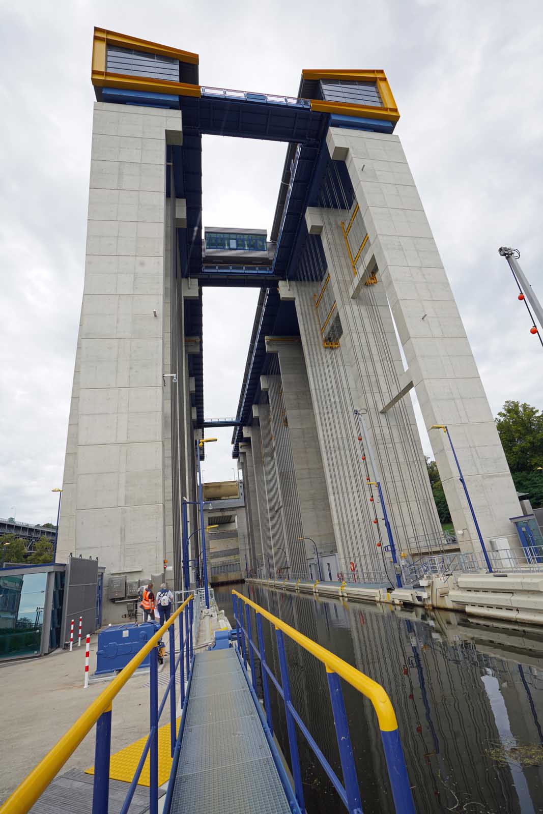
The facility consists of four pylons at each corner, approached by a canal bridge in the front and connected to the lift in the middle on the right and left. It is monitored with 16 cameras for the operation and 20 more cameras for the paths network and the gates. Access to the facility is secured with an electronic locking system. The safety doors are locked with magnets.
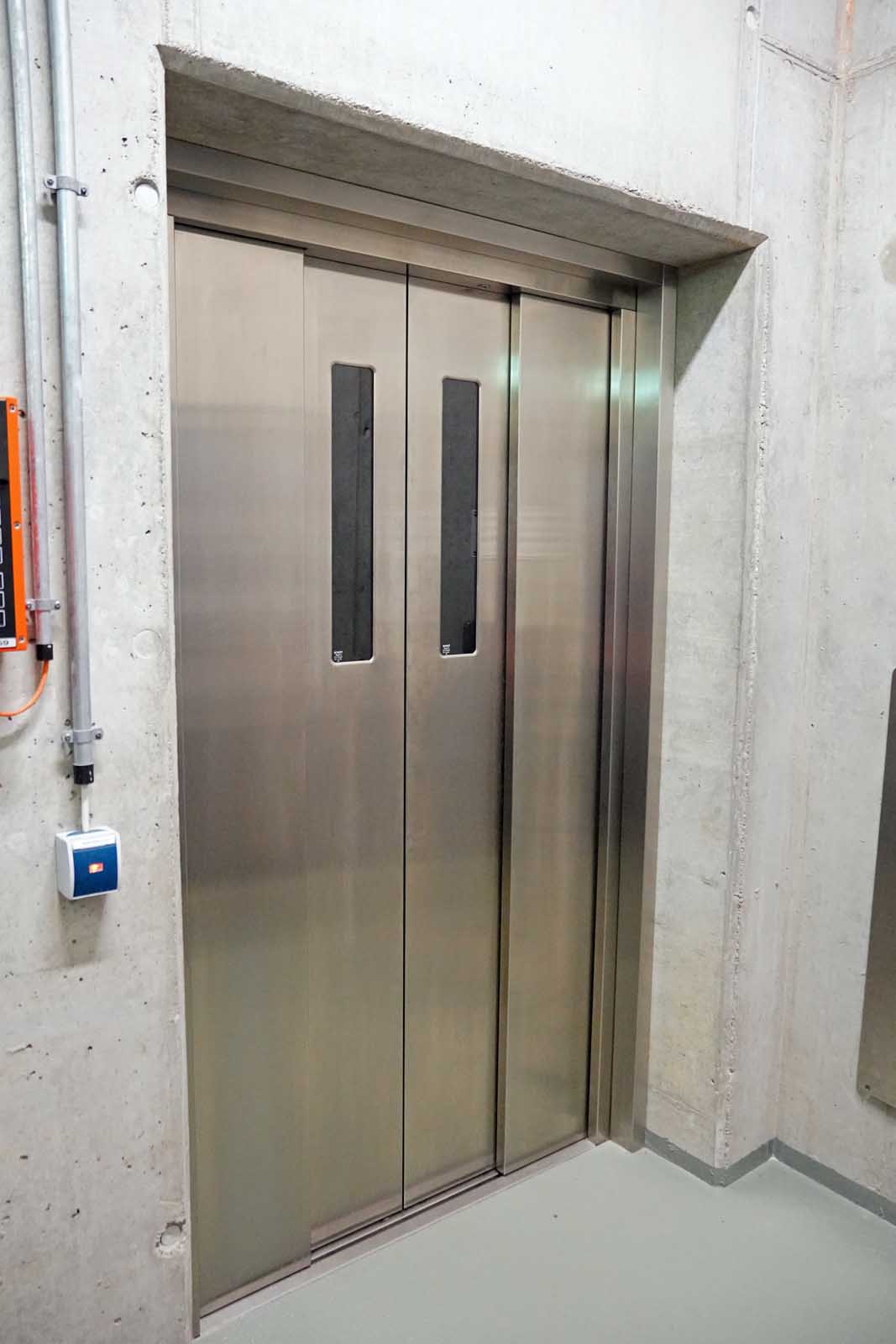
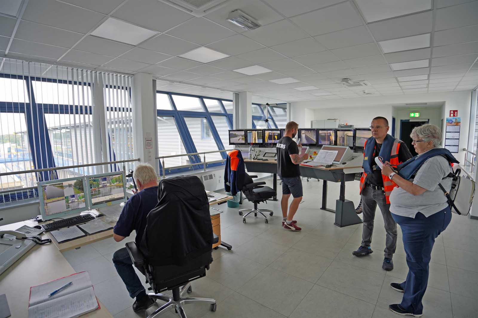
Three elevators from the company FB in three pylons travel from floors -3 to 12, 0 to 12 and -1 to 13. The elevator drives are on the 13th floor. The central control station is also located there, as well as the water pressure boosting system and wastewater collection system. Barrier-free toilets and a kitchen are also available. A moving airlock separates the control station from the pylon.
The control center for the new lift will be staffed on a two-shift basis from 05:30 to 14:15 h and from 14:00 to 22:30 h. As this is a federal waterway, a shift supervisor plus at least one operator for the new facility and one operator for the old facility (summer 09:00 to 18:00 h, winter 10:00 to 16:00 h) will always be on-site simultaneously for redundancy. The old ship lift is only operated by one on-site operator. In case of service or failures, this is also done on the new one at the front control station or with radio remote control.
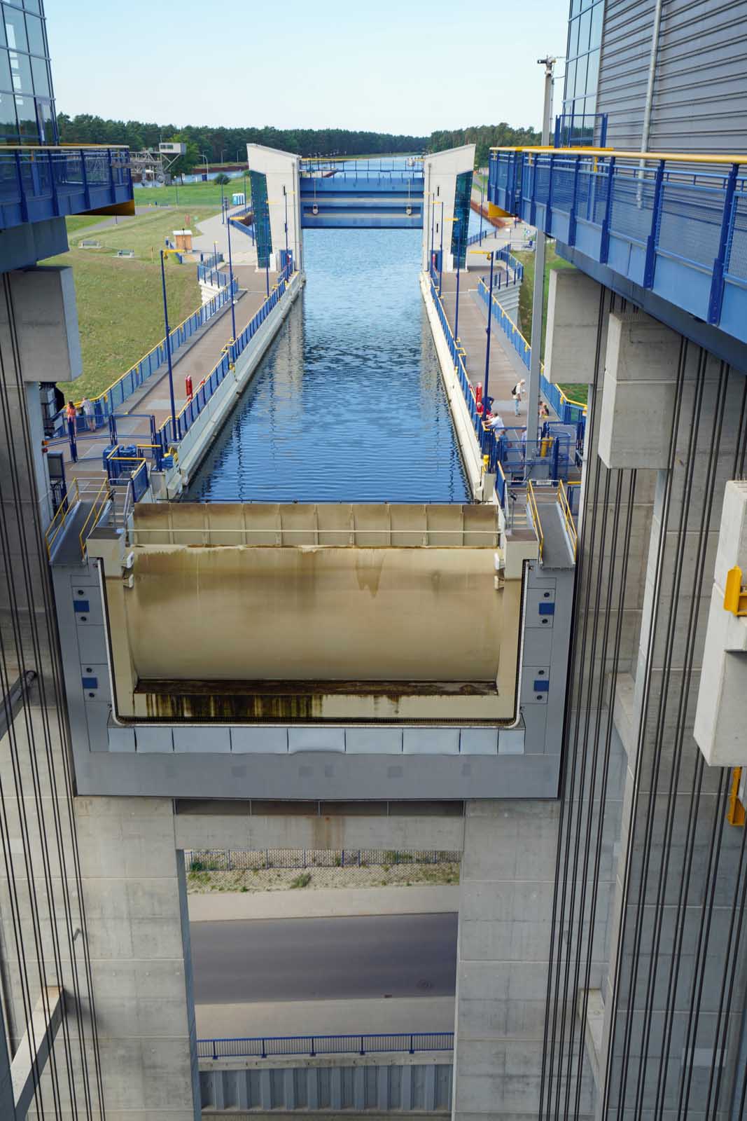
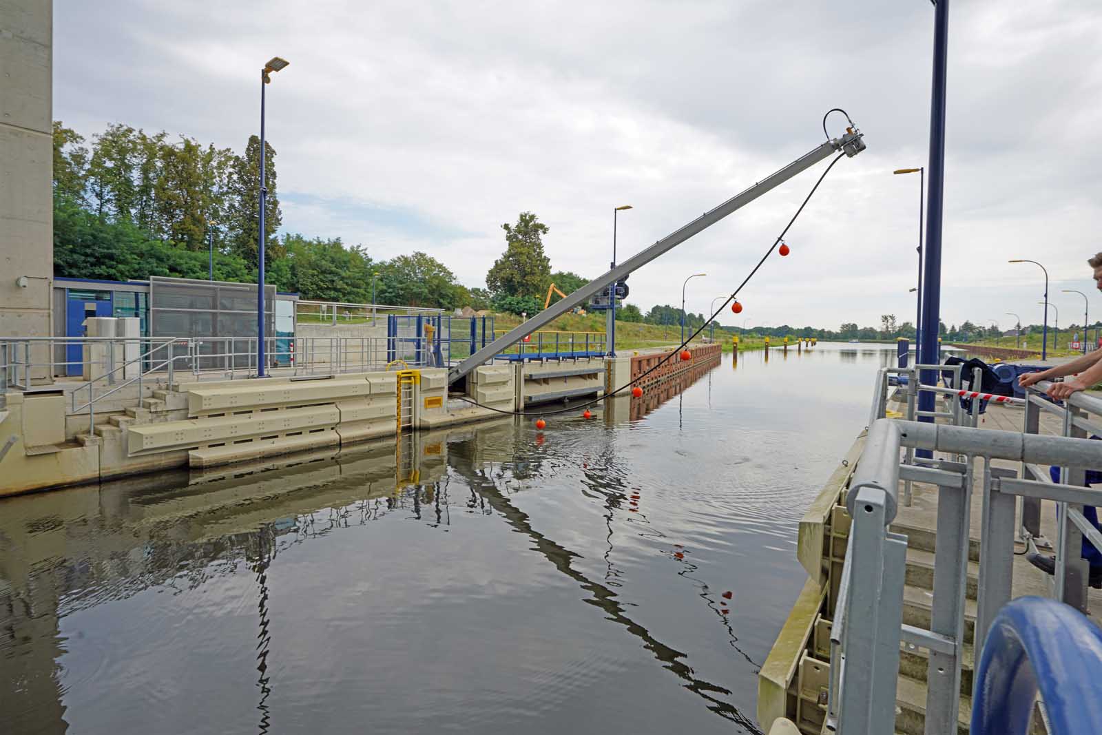
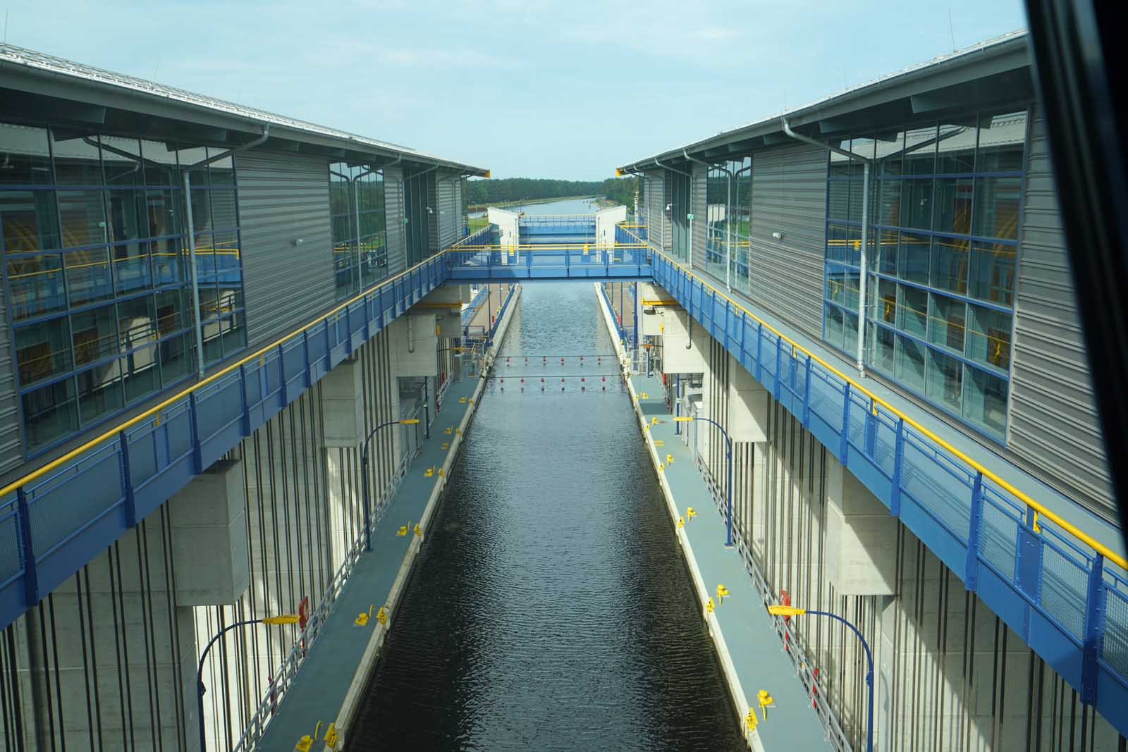
From the crossing at the canal bridge, the view leads into the trough via the watertight revolving segment gates and impact protection systems. As a precautionary measure against averages, e.g., if a ship is unable to steer, ropes in the trough protect against total loss of the gates. If a ship in the trough were to catch fire, the ropes are cooled with a water spray using a cooling system consisting of high-performance pumps and a pipe system.
The trough has a clear length of 115 m and is just under 126-m long with 12.5 m of width on the outside. When filled, it weighs around 9,800 t. It moves in a basin just under 28 m wide with a water depth of 4 m. Height-adjustable stairs are located on the trough to allow evacuation at any level of the trough.
Waterproof concrete was used in the four basement levels. The pivot bearing for the gate in front of the trough is located here. At the time of the visit, the 51-t gate was open, which means it is resting on the bottom of the trough. Pumps can correct the water level in the trough (reversing). The crane equipment for installation and service was brought in at an early stage of construction.
Mechanical and Electrical Components and Their Controls
The unit operates with 256 zinc-coated ropes, and the zinc wears off. The ropes are automatically lubricated, which also serves to protect against corrosion. The ropes are constantly inspected by sight to determine when they need to be discarded. At present, it is expected that this will not be necessary within the warranty period, but rather in about 30 to 40 years. They are also inspected every six years using induction measurement techniques to determine when they are ready to be discarded. A rope register is currently being drawn up with the zero measurement in 2022. The data from the inspections will be entered so that the repetitions will allow a prediction of the rope wear.
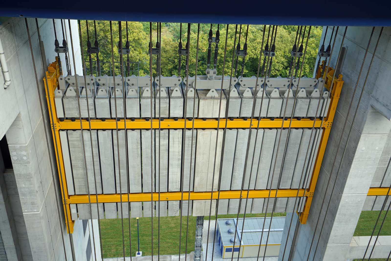
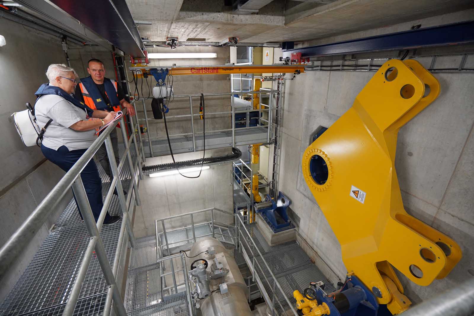
Each rope has a counterweight of 43 to 45 t. The concrete weights on the ropes are equipped with mounting lugs and guardrail plugs. They are guided in side-rails in the weight frame when they move due to the influence of cold and heat. One rope is about 67-m long, has a diameter of 60 mm and weighs 1,236 kg with fork sleeves. The elongation of the ropes was minimized by pre-stretching before installation. After approximately 5,000 trips — corresponding to just under a year of use — there has now been an elongation of a few centimeters. This was taken into account in the adjustment during installation. The frame offers enough space for this. As an aside, Schumacher notes that the Chinese bought the same ropes.
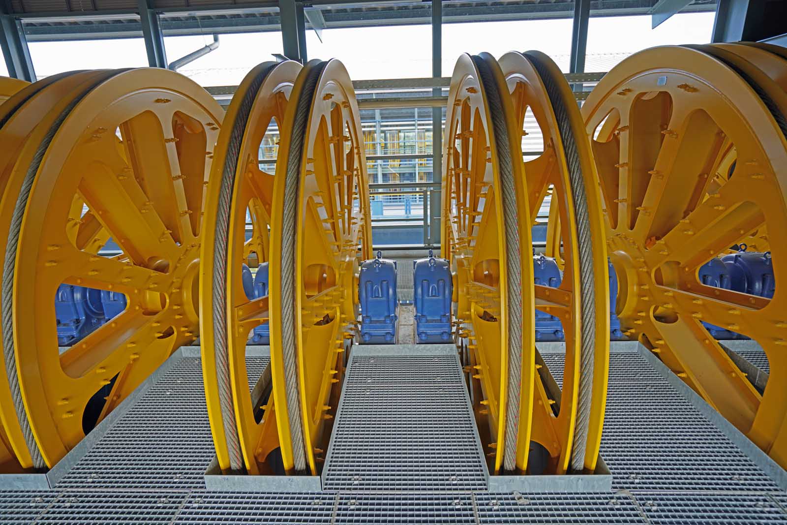
The ropes are attached in pairs, i.e., a left-attached and a right-attached lang lay rope each run in the package over a common sheave. The yellow bar frame serves as a safety device in case one rope breaks. There is a total of 2 x 112 double-grooved rope sheaves. The plastic insert in the grooves, which serves to extend the runtime of the ropes, is replaceable in sections.
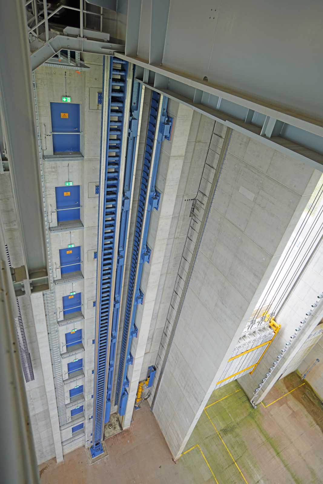
The compensation chain (far left) for the moving rope load is attached to the counterweight and the trough. If the trough is up, there is more rope (up to a maximum of 160 t) on the counterweight. The four chains weigh a total of 160 t. To the right is the trailing cable for the power supply. Again, to the right is the emergency ladder to allow emergency descent for evacuation from each floor. Then comes the rack ladder into which the pinion engages. Last in the row is the nut jaw column, which uses a non-contact screw to act as a safety system in the event of water loss in the sense of a safety gear to prevent the trough from rising. It can collect up to 6,500 t at the four points.
It is driven by eight Siemens electric motors, each rated at 160 kW. Two gearboxes, each weighing 14 t, are flanged to the motors.
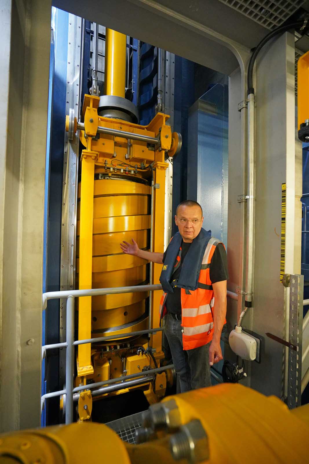
The spindle rotation lock is located in the middle between the motors, the guideway to the right of it with rollers in front and rear. The spindle (rotation lock) is made of cast steel. The self-locking thread was turned in. The threaded jaw (nut jaw column) can take up the dead loads in case of water loss to stabilize the trough over a length of 36 m in case of emergency. In operation, the spindle moves without contact. When the water is out of the trough, the spindle rests on the jaw. This construction is a patent of the engineer Löbel, who had the idea during the planning of the old ship lift. The patent’s use here was bought from him — as well as from the Chinese.
The damper spring (spring pot) compensates for water fluctuations; 1 cm more or less water in the trough corresponds to 16 t water weight.
The hydraulically controlled retaining device fixes the trough in the respective channel position. The hydraulic ram raises the bar. The bar tilts down.
The digital control system is from ABB and is operated via a WSV interface. Around 7,000 operating parameters are monitored 24/7 with sensors and logged to record and detect normal operation during travel and also faults. This is how experience and its interpretations are gathered. It has already become clear that two different basic settings will be needed: for winter and for summer at up to 30° C.
Get more of Elevator World. Sign up for our free e-newsletter.
