A17/B44 Type B Safety Stopping, Part One
Apr 1, 2018
Learn about the combination safety stop and e-stop in the first half of this Engineering series.
Learning Objectives
After reading this article, you should:
♦ Have developed a basic understanding of the characteristics of Type B safeties
♦ Have developed a basic understanding of the general theory and practice, design and A17/B44 Safety Code for Elevators and Escalators compliance of Type B flexible guide clamp safety stopping
♦ Have developed a basic understanding of the methods of field testing Type B flexible guide clamp safeties with the driving machine stopped, and with the driving machine running
♦ Have developed a basic understanding of the operational steps of the mechanical and electromechanical systems, which cause time response delays in governor and safety application
♦ Have developed a basic understanding of the incremental speed increases during the governor and safety activation process
♦ Have developed a basic understanding that the available traction, or tractive effort, between the drive sheave grooves and suspension means affects the retardation of the Type B safety stopping performance
♦ Have developed a basic understanding of the effects of and methodology behind potential “minimum assistance”
♦ Have developed a basic understanding of the combination safety and machine braking in stopping the elevator
♦ Have developed a basic understanding that, in most cases, the braking system takes longer to activate than the safety stopping time duration
♦ Have developed a basic understanding that, in the rare case when the braking system applies while the car is still being retarded by the safeties, the brake will only provide minor assistance in stopping the car, because most of the retardation is provided by the safeties
The complexity of Type B safety stopping is discussed comprehensively in this article for a contemporary audience. The history, theory and practice, design and A17/B44 Safety Code for Elevators and Escalators compliance and testing of Type B flexible guide clamp safeties will be reviewed. The term “Type B” is the North American descriptor; the term “progressive” is the term used where the European EN 81 family of codes is adopted.
The formulation and presentation of the relevant formulae and equations are necessary due to the complexity of the subject matter which deals with the elevator system motions., i.e., system dynamics. However, the commentary in both parts of this article is complete, and non-engineers will not be disadvantaged by the inclusion of the mathematics.
Originally written in relation to the binational A17/B44–2013 code,[10] which was in effect at the time of A17 Standards Committee reconsideration of A17 Interpretation 01–60,[4] references to the A17/B44-2016 code[11] are included to relate the contents of this article to the latest A17/B44 code. The following points will be presented for the benefit of engineers, designers, consultants, inspectors, mechanics, safety code professionals, manufacturers, maintenance providers, specialty contractors, users and testing entities:
- Type B FGC safeties
- Reconsideration of A17 Interpretation 01–60, which addresses combination safety stop and e-stop, i.e., a combination safety stop, emergency electrical stop, and machine brake stop
- A17 rule history relating to concurrent safety stopping and elevator system braking at an e-stop caused by the opening of an electrical protective device
- Technical points relating to safety stopping with the suspension means intact
- Technical points relating to safety stopping performance in the freefall condition where the suspension system has failed will be covered in Part Two.
- Contemporary review of A17 Interpretation 86–2[1] covering freefall safety stopping performance, originally issued three decades ago, will be reviewed in Part Two.
Depending upon the year in which a technical parameter would have been referred to in a specific edition of the A17 or A17/B44 code, the dimensional system of units might be Imperial or expressed in the SI system.[22–25] In a later section, this article refers to both dimensional systems of measurement, and the conversions from one system to the other is explained in more detail in Part Two to aid the reader in converting the variables in various equations from one system to the other. The author will attempt to present equations in both dimensional systems. Abbreviations, acronyms and notations used are defined in the last two sections of this article. Bibliographical references are given in the last section.
Type B Flexible Guide Clamp Safeties
The evolution of high-speed safeties resulted in the development of the flexible guide clamp (FGC) safety[15] in the 1920s. A17/B44[11] Requirement 2.17.5.2 indicates the essential safety characteristics of Type B safeties as functioning with a reasonably constant and uniform retarding force and providing stopping distances related to the mass being stopped and the speed at which safety application is initiated.
The main characteristics of the Type B (FGC) safeties are:
- Governor operated
- Dual wedges per assembly
- All wedges apply equally.
- Self applying after governor pull
- Factory-calibrated and preset safety springs (helical or U-springs)
- Quick applying to full retarding force
- Constant average safety retardation during slide
- Auto resettable (later versions) by lifting car, where the “self-resetting” feature was recognized per A17 definition
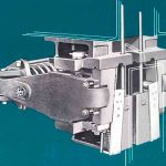
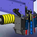
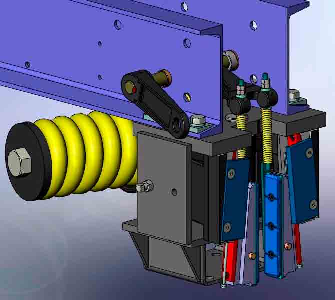
Both examples of contemporary lever style, Type B FGC safeties are shown in Figures 1 and 2. The designs utilize the helical spring and lever arms to magnify the mechanical advantage to achieve an average constant retardation. The Otis Model 14D-B FGC safety is based on the David Lindquist,[19] Fred Hymans[20] and Benjamin Thorne[21] patents.
A17/B44 Field Acceptance Safety Test
With minor exception, most enforcing authorities in North America conduct stopping performance tests of Type B safeties in accordance with the A17/B44 code. The comparison of the essential safety parameters for the field acceptance test and Category 5 test with load is shown in Table 1.
Reconsideration of A17 Interpretation 01–60
A17 Interpretation 01-60,[3] approved by the A17 Standards Committee on January 9, 2002, affirmed that the driving machine brake is permitted to assist in stopping the car during a safety test but did not quantify the “minimum assistance” provided by the driving machine. In response to a contemporary inquiry in 2013 that A17 Interpretation 01-60 be reconsidered, the A17 Standards Committee reaffirmed A17 Interpretation 01-60[6] on January 15, 2014, noting that there was no conflict between A17 Interpretations 86-2[1 & 2] and 01-60.[3]
Current ASME procedures no longer provide for a Technical Working Committee to have the intent or rationale for interpretations published as part of the interpretation. Notwithstanding, it is such an important interpretation that this article is presented to explain and memorialize the technical issues involved. The rationale for the reaffirmed A17 Interpretation 01-60 is given below as prepared by the author for the A17 Mechanical Design Committee[5] and A17 Standards Committee.[6]
The unequivocal reaffirmation of A17 Interpretation 01-60[5 & 6] is based on the following technical points:
- The technical requirement for the operability of the driving machine brake during the overspeed acceptance safety tests has withstood the test of time since the A17.1–1955 code[8] up through the present time for sound technical reasons.
- Removal of driving machine power and machine braking at the end of the safety stopping cycle minimizes the potential for counterweight jump and slack hoist ropes, both of which are caused by the tractive effort of a powered drive sheave during the safety test (Figure 4). Both of these negative effects have been clearly stated in the relevant A17.1 rule since 1955.
- The potential “minimum assistance” afforded by the driving machine brake on the safety stopping performance is nonexistent at low safety application speeds, since the total electrical, electromechanical and mechanical response time for the safety circuit to open, apply the brake and reach full braking torque exceeds the safety stopping time.
- The driving machine brake torque is limited by the technical parameters established by A17/B44–2013 Requirement 2.24.8.2. Notwithstanding, its effect in retarding the car is limited by the drive sheave available traction. Simply stated, if the braking was extremely hard and abrupt, the hoist ropes would lose traction and slip in their drive sheave grooves.
- For the car speeds where the brake applies its retarding torque after the safety retardation has been underway, the car speed will have been greatly reduced by the safety on its own (Figure 5), and its sequential contribution is minimal as compared to the retardation provided by the safety.
- While not accounted for in the formulation of A17 rules, it has been well known and understood that, once governor tripping speed (GTS) has been reached, the car continues to accelerate, while the mechanical operating clearances in the safety parts have been taken up, resulting in the safety application speed exceeding governor tripping speed. Unassisted by the machine brake, these higher application speeds are successfully absorbed by the safety on its own, prior to the deployment of the machine brake, caused by opening the SOS.
- There is no conflict between A17 Interpretation 86-2 and A17 Interpretation 01-60, since:
- Interpretation 86-2[1] (discussed in Part Two) addressed freefall safety stopping protection in the case of suspension failure, where stopping is accomplished by the Type B safety and pit oil buffer, as a combination stop, where needed.
- Interpretation 01-60[3] addressed the acceptance testing methodology for safety stopping accompanied by machine braking assistance where the suspension system is intact.
In the following sections, several historical and technical points are made in support of the operability of the driving machine brake during the safety tests.
A17 Rule History
The operability of the driving machine brake during an overspeed safety acceptance test was thoroughly discussed and debated at the A17 Mechanical Safety Devices & Machine Design Committee (A17 MSD & MD) Committee Meetings, October 10, 1951, and July 15-16, 1952, and the consensus findings were codified in the A17.1-1955 code. Notwithstanding two minor editorial changes, the technical requirements for the operational status of the safety operating switch (SOS) during the safety overspeed test have remained constant since 1955 up through the latest A17.1/B44–2016 code.
A17.1-1955[8] Rule 900.2d2 stated:
“. . .In order to assure that the safety will retard the car with the minimum assistance from the elevator driving machine and to minimize the development of slack rope and fall-back of the counterweight, the switch on the car operated by the car safety mechanism shall, for the duration of the test, be temporarily adjusted to open as close as possible to the position at which the car safety mechanism is in the fully applied position.”
A17.1/B44 – 2016[11] Requirement 8.10.2.2.2(ii)(4)(b) states:
“. . .In order to ensure that the safety will retard the car with the minimum assistance from the elevator driving machine and minimize the development of slack rope and fallback of the counterweight, the switch on the car operated by the car safety mechanism shall, for the duration of the test, be temporarily adjusted to open as close as possible to the position at which the car safety mechanism is in the fully applied position.”
Technical Points
- Since the driving machine brake, electrically assisted braking and emergency brakes are all individually activated by the governor overspeed switch (GOS), followed by the safety operating switch (SOS), prior to the safeties applying their retarding force, it is highly improbable that the two independent triggers, i.e., GOS and SOS, would both be inoperative simultaneously unless the elevator had no maintenance. A fundamental premise is that the GOS and SOS will always function reliably to remove electrical power from the driving machine motor and brake(s), so that a safety application always occurs concurrently with the activation of an e-stop.
- A traction elevator could go into overspeed due to one or more failures, thereby triggering a mechanical safety stop activated by the overspeed governor. Notwithstanding, the historical rationale for requiring the SOS to remain operational during the safety test, albeit opening the safety circuit, causing an e-stop and releasing the driving machine brake at the point when the safety wedges have reached their fully applied position was formulated by the A17 MSD & MD Committee and is based on several important considerations, which were persuasive in adopting the requirements first embodied in A17.1–1955 Rule 900.2d2. For purposes of field safety tests for regulatory purposes, the code writers have always agreed to make the GOS inoperative to simulate the single failure during the test but allow an operational SOS, albeit relocated to open at the point where the safety wedges were drawn into their fully applied position.
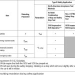
- The operability of all the speed-retarding systems involved in a combination safety and e-stop are summarized in Table 2.
- The available traction afforded by a powered drive sheave increases the counterweight jump and potential for slackening the hoist ropes above the counterweight. Making the field test while the machine continued to drive would cause slackening of the hoist ropes, which sets up unnecessarily severe stresses in the driving machine, hoist ropes and fastenings when the counterweight falls back.
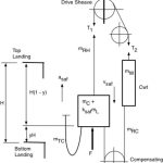
- If the SOS remained inoperative during the safety stop, the drive sheave available traction acts in the same direction of the car descending motion and functions to cause counterweight jump and slack hoist ropes above the counterweight (Figure 4). The residual traction due to the weight of the ropes would increase the stopping distance of the ascending counterweight far beyond its gravity stopping distance.
- Removal of driving machine power and machine braking at the end of the stopping cycle minimizes the potential for counterweight jump and slack hoist ropes, both of which are caused by the tractive effort of a powered drive sheave.
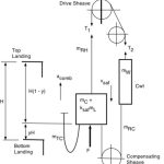
- When the SOS opens during a safety stop, the drive sheave available traction acts in the opposite direction of the car descending motion and functions to minimize the potential for counterweight jump (Figure 3).
- The validity for conducting a safety test that occurs concurrently with an e-stop is that this is exactly the real-world occurrence that would take place if the safety were to apply with the elevator in regular service.
Equations of System Motion
1) A17/B44 Test Method
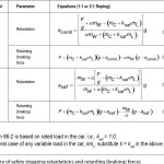
The A17/B44 test method is described in the A17.2 Guide for Inspection.[12, 13] The general equation for the retardation of the elevator system at combination safety application and e-stop, shown in Figure 3, expressed in SI units, applicable to either 1:1 or 2:1 roping, is found from the D’Alembert Method of Analysis and verified by the Hymans Equivalent System as shown below in Equation 1. The general equation is applicable to any vertical location of the car in the hoistway.

2) Non-A17/B44 Test Method
When the SOS is inoperative during the safety test, the available traction functions to cause counterweight jump and slack hoist ropes above the counterweight (Figure 4). The general equation for the retardation of the elevator system, expressed in SI units, applicable to either 1:1 or 2:1 roping, is found from the D’Alembert Method of Analysis and verified by the Hymans Equivalent System, as shown below in Equation 2. The general equation is applicable to any vertical location of the car in the hoistway.

3) Simplification of Equations
Since the masses of the suspension means, traveling cables and compensation, if used, rotational inertia of multiplying or compensating sheaves, are considerably less than the masses of the car, rated load and counterweight, i.e., they can be neglected as terms of lower orders of magnitude without compromising the accuracy of analysis. A further point in support of this (Equation 3)

simplification is that the safety tests are conducted near the approximate mid height of the hoistway, where the effects of the suspension, compensation, if used, and traveling cables tend to offset their effects. It is noted that the elasticity of the suspension ropes has a very minor effect on system retardation, but its effect is more pronounced once the car has stopped, and the elasticity of the ropes causes the car to oscillate until the stored energy in the ropes dissipates. A further simplification results from using 1:1 roped systems so that:

4) Retardations and Safety Retarding (Braking) Forces
Substituting Equations 3 and 4 into Equations 1 and 2, respectively, yields the equations shown for the retardation and safety retarding (braking) force in Table 3.
Driving Machine Braking
While “minimum assistance” to overall safety stopping might accrue to the driving machine brake capability, its minimal contribution is offset by the increase in car speed from governor tripping speed to the speed at which the safety wedges are drawn into their fully applied position, due to the time delay of moving the safety linkages and operating parts. This speed increase isn’t taken into account by the safety stopping distance limits but was understood by the early A17 code writers based on the NBS/NEMI Safety Testing Program sponsored by NEMI, the predecessor to NEII, during the 1930s-1940s.
The effect of the driving machine brake capability in contributing to a combination safety and brake stop is limited by the available traction in the drive sheave grooves through which all mechanical braking must be transmitted. By comparison, the limiting retardation value that can be sustained by the available traction is approximately:

The range of allowable average retardations permitted by A17[8 & 9] and A17/B44[10 & 11] for Type B FGC safeties with constant retarding force is usually expressed by the approximate relationship

However, the equations established in the A17-1931 code[7] edition, up through the current A17/B44 code, are based on the following equations, the last term in which represents the safety wedge height, as applicable:
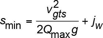
and
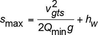
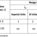
where the values from the current A17/B44 code are given in Table 4.
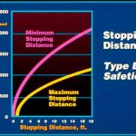
The allowable safety stopping distances based on Equations 11 and 12 are illustrated in Figure 5. A17/B44[11] Requirement 2.17.3 references A17/B44 Section 8.2.6, Table 2.17.3 and Figure 8.2.6. In writing this article, the author noticed that Figure 8.2.6’s ordinate axis incorrectly refers to rated speed, whereas it should pertain to governor tripping speed. Excluding the wedge height allowance in the A17/B44 safety stopping distance equations, the allowable retardation range for safety stopping with full load in the car is:

where the retardation constants are given as:


and

Substituting Equation 14 and 16 in 13 yields:

and, at the median allowable retardation:

Due to the safety, the safety stopping retardation would be 2.5 times the brake contribution, even if they occurred simultaneously.
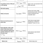
When an SOS actuates, or trips, there is a small time delay during which the SOS operates, causing the removal of power through other devices, and then the driving machine brake is released. The total time duration, ttbd , varies depending on the type, age and design of equipment. The total electromechanical response time delay from time of initial SOS switch activation until full mechanical braking torque is effective, ttbd , is influenced by the incremental delays shown in Table 5.
The typical industry values for the machine braking response time shown in Table 5 can be assessed further to quantify car speed values below which the car safety stop would be reached prior to the driving machine brake coming into play and applying full braking torque. This is the same condition as the A17/B44 test method, in which the GOS is inoperative in the acceptance test and ineffective in the Category 5 test, so that in either case, only the SOS is operative. If, during regular elevator operation, the car went into overspeed, and the governor responded, but the GOS was inoperative or otherwise not functioning, the governor would mechanically trip, thereby activating the safeties. As the safety wedges were deployed, the SOS would be activated, and the same response times discussed in Table 5 would occur.
The total electrical, electromechanical and mechanical response time delay from time of initial SOS switch activation until full mechanical braking torque is effective is:

The constant retardation range given by Equation 17 is used. The general equation for uniform rectilinear motion with constant retardation is used:

The numerical values are shown in Table 5. Since A17/B44[11] Requirement 8.10.2.2.2(ii)(4)(a) is premised on the safety application speed being equal to the governor tripping speed, i.e.,

these will be used.
While the extremes of the allowable retardation range can be used, most major elevator manufacturers target the median values when setting up their designs. Accordingly, these are highlighted in Table 6. As an example, the median value of the mechanical, electrical and electromechanical response-time delay is found by substituting the median value from Table 5 in Equation 19 so that:

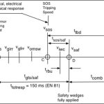
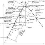
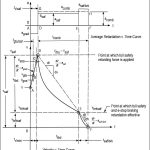
The timeline for the safety and e-stopping events at a field safety acceptance test is shown in Figure 6. The motion diagrams for the car are shown in Figures 7 (v-t curve) and 8 (v-t and a-t curves). The timeline and curves are not to scale and shown for illustrative purposes. Nodal points are designated by small circles in Figures 6-8 at their respective event points.
During the time interval,, between governor tripping speed (point B) and the point at which the safety wedges are in the fully applied position (Point D), and full safety retardation begins, the SOS opens (point C), and mechanical, electrical and electromechanical response time delays occur (Table 5 and Equation 19), leading up to the onset of e-stopping retardation by the machine brake, electrically assisted braking and emergency brake, if provided. If the safeties, on their own, have not fully stopped the car by the time the e-stop retardation starts (point E), the descending car, albeit at a greatly reduced speed, will be retarded and stopped by the concurrent retardation,asaf/brk, between points E and F shown on both the v–t and a–t curves in Figure 7.
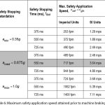
Table 6 illustrates the speeds for three different retardations of the safety on its own. For purposes of an example, the time interval between the opening of the SOS and the start of full safety retardation will be assumed so small as to be negligible, so that:

and the safety application speed is that given by (21), i.e., vsaf=vgts.
It will be assumed that Equation 22 gives the median value of the time response delay. Substituting the median retardation and median time response delay in Equation 20 yields:

Therefore, a car descending at a governor tripping speed of 717 fpm will be stopped by the safety, on its own, prior to the e-stop occurring. This is shown in the shaded portion of Table 6.
The numerical values in Table 6 highlight two fundamental conclusions:
- The potential “minimum assistance” afforded by the driving machine brake on the safety stopping performance is nonexistent at low safety application speeds, i.e., below a safety application speed of 717 fpm shown in the example, since the total response time for the safety circuit to open, apply the brake and reach full braking torque exceeds the safety stopping time.
- Where the machine braking system is able to apply full braking torque before the safety has stopped the car, the tractive effort at the drive sheave will act in the opposite direction of the car descending motion (Figure 3) and will function to minimize the potential for counterweight jump and the attendant slack hoist rope condition. This condition is illustrated in Figure 8 between points E and F.
The terminology used in the code rule “minimum assistance” is appropriate, since:
- The driving machine brake torque is limited by the technical parameters established by A17/B44[11] Requirement 2.24.8.2. Its effect in retarding the car is limited by the drive sheave available traction.
- For the car speeds where the brake applies its retarding torque (Figure 8, point E) after the safety retardation has been underway (Figure 8, between points D and E), the car speed will have been greatly reduced by the safety, on its own, and its sequential contribution is minimal as compared to the retardation provided by the safety. This condition is illustrated in Figure 8 between points E and F.
While the premise of setting the safety application speed equal to the governor tripping speed reflects sound engineering practice, which has been embodied in A17.1 since its early editions, it is important to discuss the fact that, depending on the inherent mechanical and electromechanical delays, or response times, in the system, the car speed at the point where the Type B safety wedges are drawn into their full application position, the car safety activation speed will be greater than governor tripping speed, i.e.,

Figure 7 illustrates the speed increase for any generalized traction elevator system in which the car speed continues to increase beyond rated speed (point A) up through the various incremental points at which electrical, electromechanical and mechanical events occur prior to the safety applying its full retarding force at point D. The speed increase was first discussed in the findings of the NBS/NEMI safety test program conducted in the 1930s, sponsored by NEMI.
Regardless of the test method used to reach governor tripping speed during an overspeed safety test, the car must be accelerated to increase its speed from rated speed (point A) to governor tripping speed (point B). This acceleration gradient,, will continue to be effective until the safety wedges are drawn into their full application position at point D. The general curve, shown in Figure 7, illustrates either safety operation with the suspension means intact, or freefall. However, in the case of freefall, an e-stop will only remove power from the driving machine, and no mechanical braking is possible.
In the case of safety application during an overspeed test with the suspension means intact, the acceleration gradient will be somewhere in the range between the normal elevator acceleration and the limiting acceleration value at which traction would be lost, i.e.,

In the case of a freefall, the freefall acceleration is equal to the acceleration gradient, i.e.,

where the acceleration gradient cannot exceed the acceleration due to gravity:

Over the last several years, EU code writers have recognized the time response of the governor and safety operating parts from the point of governor tripping until the FGC (progressive) safety wedges are in their fully applied position and have codified requirements in EN 81-1[16] Clause 9.9.7, EN 81-20[17] Clause 5.6.2.2.1.2 and EN 81-50[18] Clause 5.3.2.3.1, which are extrapolated to result in a total time delay response,

While not accounted for in the formulation of A17 rules, it has been well known and understood that, once governor tripping speed has been reached, the car continues to accelerate, while the mechanical operating clearances in the safety parts have been taken up, resulting in the safety application speed exceeding governor tripping speed as given by Equation 23. Unassisted by the machine brake, these higher application speeds are successfully absorbed by the safety, on its own, prior to the deployment of the machine brake, caused by opening the SOS.
The foregoing discussion of the safety application speed being greater than governor tripping speed highlights an additional conclusion that can be drawn, viz., the stepped retardation (Figure 8, a-t curve) resulting from the safety application at a speed higher than governor tripping speed, followed by the delayed machine braking, provides a combination retardation that would only be marginally different than the safety retardation alone at the lower application speed.
In Figures 6 and 7, the incremental steps occurring during the motion of the elevator from the onset of an overspeed up to the point of the safety wedges applying full retarding forces to the guide rails was discussed to show how the car speed continues to increase during these steps.
The system motion in terms of car velocity and acceleration (retardation) from the onset of the overspeed to the end of motion when the car has been brought to a safe stop due to safety application, followed by combined safety application and brake application, is shown in Figure 8.
The same case as above is discussed, i.e., either during regular elevator operation, the car went into an overspeed, and the governor responded, but the GOS was inoperative, or, as required for an acceptance test, the governor would mechanically trip, thereby activating the safeties and SOS.
Since the velocity and acceleration are a function of each other, the “Velocity v. Time (v-t) Curve” is shown together with the “Acceleration v. Time (a-t) Curve” displayed immediately above it in Figure 8. For convenience of illustration, the time clock for the events under study will be taken at the onset of car motion where it is descending at rated speed, v , and is shown starting at time t = 0.
The sequence of events shown by Figures 6-8 is as follows:
- The car is descending at rated speed, v, as shown at point A.
- For an elevator operating in regular service, either a failure occurs, and the descending speed increases, or, if an acceptance test is being run, the car speed is deliberately increased. For either case, the GOS is not functioning.
- The car speed increases due to an acceleration gradient, agrad, until the speed reaches the speed for which the GOS is set to trip. But, nothing happens, since the GOS is not functioning.
- The car speed continues to increase until it reaches vgts (point B) on the v-t curve, i.e., where governor tripping occurs, causing the governor to mechanically activate the safety operating parts. While these mechanical response times are taken up, the car speed increases to point B where the SOS is opened at the speed, vsos, thereby opening the safety circuit.
- Due to the time response delays in activating the safety wedges and moving them into their full retarding force position (point D), the car speed has now attained the speed vsaf, and the FGC safety wedges apply their full retarding force, F.
- During this phase, the car speed is reduced solely by the FGC safety by the retardation, asaf , as shown between points D and E. Once the system electrical, electromechanical and mechanical response time delays have been reached, the brake exerts full torque at point E on the v–t curve, and any further speed reduction is retarded by the combination safety and brake at a value,asaf/brk, between points E and F.
- From the point of safety application (point D) to the end of the combination safety and brake application at point F, the total stopping time is tcomb.
- During the time interval shown between points D and F, the average retardation is shown by the horizontal dashed line in the a–t curve as acomb.
Abbreviations, Acronyms and Terms
For the purposes of Parts One and Two of this article, the following apply:
A17/B44 = ASME A17.1/CSA B44 Safety Code for Elevators and Escalators
- AHJ = authority having jurisdiction
- DWT = double-wrap traction
- EPD = electrical protective device
- e-Stop = emergency electrical stop
- EU = European Union
- FGC = flexible guide clamp safety
- fpm = feet per minute
- GOS = governor overspeed switch
- GTS = governor tripping speed
- MSD and MD = A17 Mechanical Safety Devices and Machine Design Committee
- ms = millisecond
- mps = meters per second
- NBS = National Bureau of Standards
- NEII = National Elevator Industry, Inc.
- NEMI = National Elevator Manufacturing Industry, Inc. (predecessor to NEII)
- SI = system of dimensional metric units
- SOS = safety operating switch
The meaning of terms not specifically defined in this article shall be as defined by technical books and publications, codes and standards, and/or collegiate dictionaries in the sense that the context implies.
Notations & Nomenclature
- a = Average safety stopping retardation of the car at safety application (general) (used in A17 Interpretation 86-2) (mps2 or fps2)
- acff = average acceleration of freely falling car (mps2 or fps2), acff =1.0g
- acomb = average retardation of car due to combined safety application and e-stop (mps2 or fps2)
- ae-stop = average retardation of car due to e-stop alone (mps2 or fps2)
- agrad = average acceleration gradient occurring between rated speed, v, and the speed of the car at the point at which all the FGC safety wedges make initial contact with the guide rails, viwc, during field acceptance overspeed test (mps2 or fps2)
- amax = A17/B44 maximum average safety stopping retardation based on Q =1.0 (mps2 or fps2)
- amed = Median average A17 safety stopping retardation based on Q limits (mps2 or fps2)
- amin = A17 code minimum average safety stopping retardation based on Q = 0.35 (mps2 or fps2)
- an = normal operating acceleration/retardation of elevator (mps2 or fps2)
- asaf = average retardation of car due to safety application only (mps2 or fps2)
- asaf/brk= combined average retardation of car due to safety application and e-stop (mps2 or fps2)
- aα = system retardation (average) at impending suspension rope slip at drive sheave (mps2 or fps2)
- C = car weight (lbf)
- dv= incremental velocity differential
- dt = incremental time differential
 = first derivative of velocity with respect to time (mps2 or fps2)
- f (v) = a function of speed
- F = total safety retarding (braking) force from all safety assemblies (general term) (N or lbf)
- g = acceleration due to gravity (9.80665 mps2 or 32.17405 fps2)
- H = travel (rise) (m or ft.)
- hw = vertical height allowance for Type B FGC safety wedge at maximum slide (mm or in.)
- Jw = vertical height allowance for Type B FGC safety wedge at minimum slide (mm or in.)
- Ksaf = rated load ratio during A17/B44 overspeed test (ksaf =1.0) (dimensionless)
- L = rated load (weight) (lbf)
- M = constant term used to describe safety activation speed as a function of governor tripping speed (dimensionless); also used for mass and moment of force.
- mc = mass of car (kg)
- mcf = mass of compensating sheave assembly (kg)
- mcs = mass of car 2:1 sheave(s) (kg)
- md= mass of deflector/secondary sheave (kg)
- mL = rated load (mass) (kg)
- mRC = mass of single run of compensation (kg)
- mrcs = mass of compensating sheave(s) (kg)
- mRH = mass of single run of suspension means (kg)
- mshvs= mass of all sheaves in system (general) (kg)
- mTC = mass of traveling cables (kg)
- mW = mass of counterweight (kg)
- mWS = mass of counterweight 2:1 sheave(s) (kg)
- n = car/counterweight roping ratio ( n= 1 for 1:1; n= 2 for 2:1)
- n/a = not applicable
- Q = retardation constant used for A17/B44 safety stopping distances (dimensionless)
- Qmax = retardation constant used for A17/B44 minimum safety stopping distance (Qmax =1.0) (dimensionless)
- Qmed = retardation constant used for A17/B44 safety stopping distance based on the median retardation (Qmed = 0.675) (dimensionless)
- Qmin = retardation constant used for A17/B44 maximum safety stopping distance (Qmin = 0.35) (dimensionless)
- RC = weight of single run of compensation (lbf)
- Rh = weight of single run of suspension means (lbf)
- S = safety stopping distance (general term) (m or ft.)
- Smax = Maximum safety stopping distance allowed by A17/B44 (m or ft.)
- Smin = Minimum safety stopping distance allowed by A17/B44 (m or ft.)
- t = time duration for an event (general) (ms or s.)
- tbmd = machine brake mechanical delay, measured from brake coil(s) release, brake shoe(s) motion, brake components seating under maximum braking load, onset of full brake torque (ms or s.)
- tcomb = time duration for a combined safety application and e-stop (brake stopping) of the car from Vsaf to full stop (ms or s.)
- tgos/gts = time duration from the point at which governor overspeed switch setting is reached to governor tripping speed (ms or s.)
- tgts/omsw = time delay from governor tripping speed to onset of motion of car safety levers and safety wedges (ms or s.)
- tgts/saf = time delay from governor tripping speed to start of full safety application (ms or s.)
- tiwc/saf = time duration for safety retardation to build up from initial wedge contact with the rail until the wedge is in its fully applied position (ms or s.) (tiwc/saf = trbu)
- tomsw/iwc = time duration from the point of onset of motion of car safety levers and safety wedges to the point initial safety wedge contact with the guide rails (ms or s.)
- tomsw/sos = time duration from the point of onset of motion of car safety levers and safety wedges to the point at which the safety operating switch opens (ms or s.)
- tpam = time duration for pre-activation motion of EPD (ms or s.)
- trbu = time duration for safety retardation to build up from initial wedge contact with the rail until the wedge is in its fully applied position (ms or s.) (trbu = tiwc/saf)
- tsaf /brk = time duration from the point at which the concurrent safety and e-stop braking starts until the car is stopped (ms or s.)
- tsafckt /coil = time delay from opening safety circuit to removal of electrical power to brake coil(s) (ms or s.)
- tsos/saf= time duration from the opening of the SOS until full safety retardation starts (ms or s.)
- tsos/safckt = time delay from onset of opening of SOS to opening safety circuit (ms or s.)
- ttbd= total electromechanical response time delay from time of initial SOS switch activation until full mechanical braking torque is effective (ms or s.)
- ttbdmed = median electromechanical response time delay from time of initial SOS switch activation until full mechanical braking torque is effective (ms or s.)
- ttotresp = total time delay response from the point of governor tripping until the FGC safety wedges are in their fully applied position per EN 81 (ms or s.)
- tv/gos= time duration from the point of rated speed to the point at which governor overspeed switch (GOS) setting is reached (ms or s.)
- tv/saf = time duration from the point of rated speed to the speed at which the safety is in the fully applied position (ms or s.)
- tv/sos = time duration from the point of rated speed to the point at which the safety operating switch (SOS) switch setting is reached (ms or s.)
- To = magnitude of onset brake torque (N.m or ft.-lbf)
- Tbmk= available kinetic brake torque due to mechanical brake sets, on their own, reflected to drive sheave/drum (N×m or ft.-lbf)
- Teab = kinetic brake torque due to electrically assisted braking, reflected to drive sheave/drum, if provided (N×m or ft.-lbf)
- Teb = effective kinetic torque due to emergency brake, reflected to drive sheave/drum (N×m or ft.-lbf)
- Tmax = magnitude of full brake torque (N×m or ft.-lbf)
- T1 = hoist-rope tension at point where ropes lead from drive sheave to car (N or lbf)
- T2= hoist-rope tension at point where ropes lead from drive sheave, or deflector sheave, if furnished, to counterweight (N or lbf)
- V = speed (velocity) of the car (general) (mps or fpm)
- V = rated speed (velocity) (mps or fpm)
- vbrksaf = car speed at the point at which the brake full torque is effective, in addition to the previously applied safety retarding force (mps or fpm)
- vf= speed of car when suspension fails or an overspeed starts (mps or fpm)
- vgfrr = car speed at point of full governor rope retarding means position (mps or fpm)
- vgirr = car speed at point of onset of mechanical activation of governor rope retarding means position (mps or fpm)
- vgos = speed at which the governor overspeed switch opens (mps or fpm)
- vgts = governor tripping speed, as calibrated (mps or fpm)
- vgtsmg = speed at which manual governor tripping performed (general term) (mps or fpm)
- vgtsmv = manual governor tripping performed at rated speed (mps or fpm)
- viwc = car speed at the point of initial safety wedge contact with the guide rails (mps or fpm)
- vomsw = car speed at point of release of releasing carrier, if provided, and onset of motion of car safety levers and safety wedges (mps or fpm)
- vrbu = car speed during safety retardation buildup as wedges are drawn into their fully applied position (mps or fpm)
- vsaf = car speed at which safety applies full retarding force (mps or fpm)
- vsaf1 = theoretical peak value of the speed at which the safety wedges apply their full retarding force (mps or fpm)
- vsos = car speed at which the SOS opens (mps or fpm)
- vtbd = magnitude of the car speed reduction from the start of full safety application during the total electromechanical response-time delay from time of initial SOS switch activation until full mechanical braking torque is effective (mps or fpm)
- y = position ratio to describe location of car in relation to hoistway/well position above lowest landing
 (dimensionless)
 - Zi = constant value based on specific sheave dimensions, which, when multiplied by the respective sheave mass/weight, gives its rotational inertia effect (zcs , zd , zrcs , zws etc.)
 = available traction (tractive effort) between drive sheave and suspension means (dimensionless)
 = constant term used to describe governor tripping speed as a function of rated speed (dimensionless)
- > = greater than
- < = less than
 = equal to or greater than
 = equal toor less than
 = approximately equal to
-
 = significantly greater than
 -
 = significantly less than
- Figure 1: Type B (FGC) Safety: Otis Model 14D-B
- Figure 2: Type B (FGC) Safety: thyssenkrupp Elevator Model 63200
- Figure 3: Traction minimizes counterweight jump (A17/B44 test method).
- Figure 4: Traction lifts counterweight (non-A17/B44 test method).
- Figure 5: Type B safety stopping distances
- Figure 6: Timeline for safety and e-stopping events at acceptance test
- Figure 7: Velocity-time curve for generalized safety application
- Figure 8: Motion curves for generalized combined safety and brake application
- Table 1: Summary of essential safety parameters for acceptance and Category 5 safety tests
- Table 2: Systems providing retardation during safety application
- Table 3: Summary of safety stopping retardations and retarding (braking) forces
- Table 4: A17/B44 safety stopping constants
- Table 5: Braking response times
- Table 6: Maximum safety application speed attained prior to machine braking
Learning-Reinforcement Questions
Use the below learning-reinforcement questions to study for the Continuing Education Assessment Exam available online at www.elevatorbooks.com or on p. 141 of this issue.
♦ Why is it important to have reviewed the A17/B44-2016 requirements for the design and testing of overspeed governors, Type B safeties and brakes?
♦ Why is it important to have a basic understanding of the differences in performing acceptance tests and Category 5 tests of Type B safeties?
♦ Why is it important to have a basic understanding of the motions of the elevator once an overspeed is detected?
♦ Why is it important to understand the various steps that occur in the governor and Type B safety system as the governor and safety mechanical parts are activated, including electromechanical time response delays, prior to the safety applying its full retarding force?
♦ Why is it important to understand the effects of electrical and electromechanical time response delays on the braking system in initiating an e-stop?
♦ Why is it important to understand that, when a field overspeed test is being conducted on the Type B safety, the operational safety operating switch will initiate an e-stop, which will occur after the safeties are already stopping the elevator?
♦ Why is it important to understand that, in the time interval between the governor tripping and the Type B safety applying its full retarding force, the car speed continues to increase, and that the safety must retard the car from a speed higher than governor tripping speed?
♦ Why is it important to understand that the available traction, or tractive effort, between the drive sheave grooves and suspension means affects the selection of a safety retarding force for a Type B safety?
♦ Why is it important to understand the major differences in safety stopping performance between the A17/B44 test method where the machine might become stopped by the opening of an EPD toward the latter part of the safety stopping and the non-A17/B44 field test method, where the driving machine remains powered during the safety test?
♦ Why is it important to understand the effects of a powered driving machine on the suspension means and counterweight during a field overspeed safety test?
References
[1] A17 Interpretation 86-2; A17 Main Committee Approval, 03/11/87; A17 Elevator and Escalator Interpretations, Interpretations Book No. 11, November 1986 – April 1987.
[2] Gibson, G.W., “Stopping Capability of Safeties”, ELEVATOR WORLD,
July 1988, p. 98-103.
[3] A17 Interpretation 01-60; A17 Committee Approval, 01/09/02; A17 Elevator and Escalator Interpretations, Interpretations Book No. 25, June 2001-June 2002.
[4] Request for Reconsideration of A17 Inquiry 01-60, 06/21/13.
[5] Minutes, A17 Mechanical Design Committee, 01/13/14 & 01/14/14,
Item 7.1.
[6] Minutes, A17 Standards Committee, 01/15/14, Item 6.1, Reaffirmation of A17 Interpretation 01-60.
[7] ASA A17–1931 Safety Code for Elevators, Dumbwaiters and Escalators.
[8] ASA A17.1–1955 American Standard Safety Code for Elevators, Dumbwaiters and Escalators.
[9] ASME A17.1–2000 Safety Code for Elevators and Escalators.
[10] ASME A17.1-2013/CSA B44 – 13 Safety Code for Elevators & Escalators.
[11] ASME A17.1-2016/CSA B44 – 16 Safety Code for Elevators & Escalators.
[12] ASME A17.2–2010 Guide for Inspection of Elevators, Escalators and
Moving Walks.
[13] ASME A17.2–2014 Guide for Inspection of Elevators, Escalators and
Moving Walks.
[14] ASME A17.1/CSA B44 Handbook, 2013 Ed.
[15] “Descriptions and Schematic Layouts of Various Types of Undercar Safeties and Governors,” Elevator Maintenance Bulletin No. 5, ASME, October 1945.
[16] EN 81-1:1998 + A3:2009 Safety Rules for the Construction and Installation of Lifts, Part 1: Electric lifts.
[17] EN 81-20:2014 Safety Rules for the Construction and Installation of Lifts — Lifts for the Transport of Persons and Goods – Part 20: Passenger and Goods Passenger Lifts.
[18] EN 81-50:2014 Safety Rules for the Construction and Installation of Lifts – Examinations and Tests Part 50: Design Rules, Calculations, Examinations and Tests of Lift Components.
[19] U.S. Patent No. 1,789,008, “Elevator Safety System,” David L. Lindquist (January 13, 1931).
[20] U.S. Patent No. 2,150,373, “Elevator Safety Device,” Frederick Hymans (July 2, 1937).
[21] U.S. Patent No. 3,441,107, “Flexible Guide Clamp Safety System,” Benjamin G. Thorne, et al (April 29, 1969).
[22] IEEE/ASTM SI 10-1997 Standard for the Use of the International System of Units (SI): The Modern Metric System
[23] ASME Guide SI-1, Orientation and Guide for Use of SI (Metric) Units
[24] IEEE/ASTM SI 10-2016, American National Standard for Metric Practice
[25] CAN/ CSA-Z234.1, Canadian Metric Practice Guide (Latest Edition).
Get more of Elevator World. Sign up for our free e-newsletter.
