Analysis and Calculation of Elevator Car Fall Incidents Caused by Serious Damage of Diverter Pulley Bearing
Apr 4, 2024
Serious incidents reviewed.
In recent years, there have been some serious incidents in which the failure of the diverter pulley caused the counterweight to fall and eventually led to the fall of the car. The author of this article has collected six such cases from 2023, 2022, 2021, 2019, 2018 and 2008. The suspension of the elevator is very demanding. It not only requires redundancy and the safety factor requires more than 12, but the support of the diverter pulley of the counterweight included in the suspension system is so fragile that a foreseeable single failure can cause the car to fall, to which the industry should pay great attention.
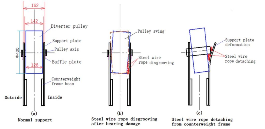
Among several car fall incidents caused by the failure of the counterweight diverter pulley, no fewer than three incidents were caused by the serious damage of rolling bearings. The bearings are blocked or stuck and unable to turn; the force of the steel wire ropes is transferred from the diverter pulley to its axle; the rotation of the axle then transfers the force to the baffle plate; then, the force is transferred from the baffle plate to the fixed bolt, and one of the two fixing bolts on both sides of the baffle is sheared off. The axle that loses the baffle stop function is detached from the support plate of the pulley, the steel wire ropes are detached from the counterweight frame, the counterweight falls into the well, and the car that loses the counterweight traction also falls into the well.
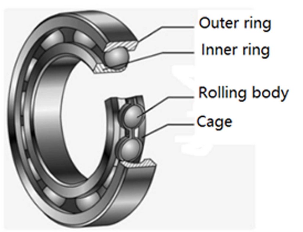
When the rolling bearing is seriously damaged, there is a certain probability of a stuck failure mode, which is due to its scattered cage, broken ball fragments or foreign dust and other foreign objects that jam the ball between the inner and outer rings.
At present, most diverter pulley designs do not take this failure mode into account. The strength of the general baffle bolt is insufficient, and it cannot resist the shear force generated by this failure mode once the stuck failure mode occurs. In addition, the general calculation of the bearing design life is carried out in accordance with 90% reliability — that is, in bearing design life, the failure of the bearing is foreseeable and unavoidable. Of course, the general bearing damage is a process, accompanied by rotating noise, vibration, temperature rise, swing and other characteristics in the process of damage, but because the maintenance personnel cannot follow the counterweight to check the rotation state of the bearing — that is, the detectability for the counterweight diverter pulley — bearing damage is low, and the problem is hard to spot.
1. Some Serious Falling Incidents of the Counterweight and Car Are Caused by the Failure of the Counterweight Diverter Pulley Bearing
1.1 The Common Structure of the Counterweight Diverter Pulley Before
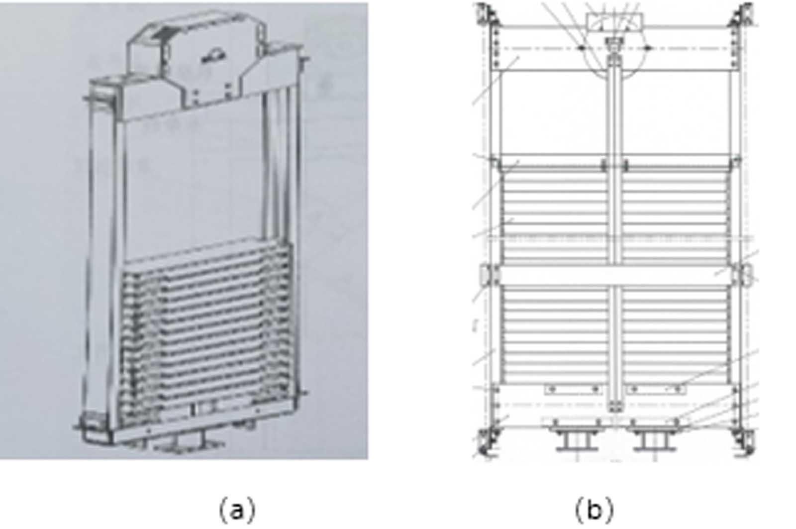
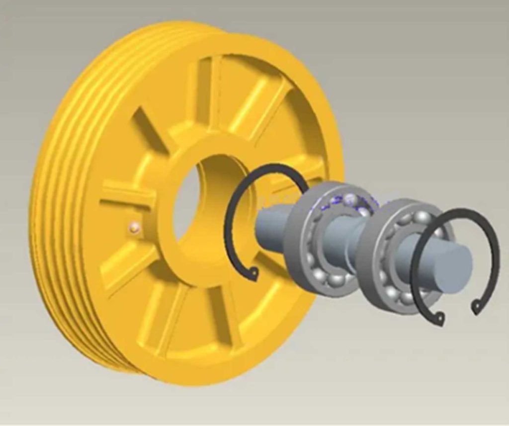
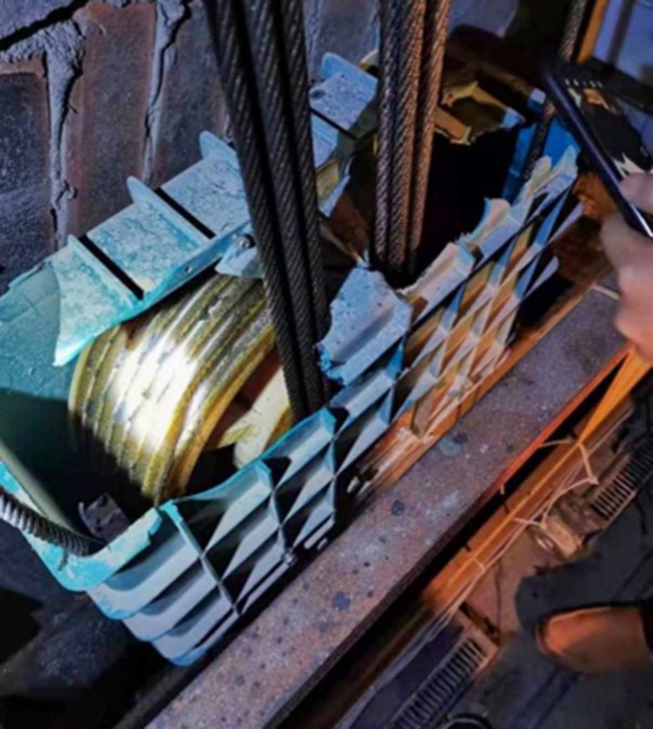
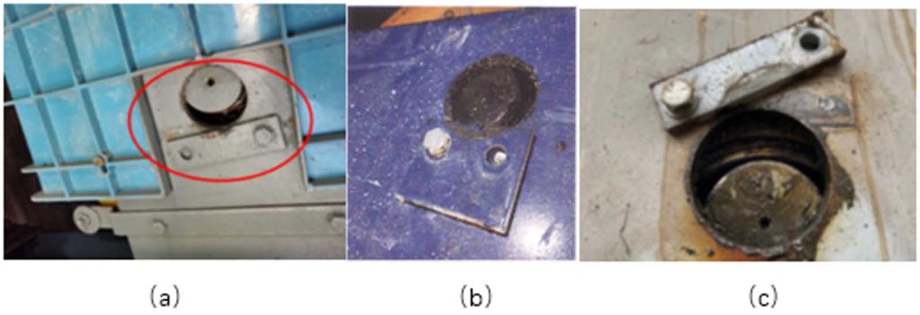
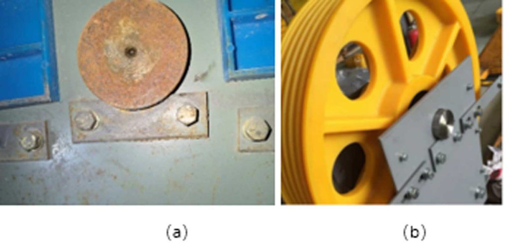
Change to: Figure 1 (a) and (b) is the common structures of the counterweight diverter pulley before; Figure 2 is the common structure diverter of pulley and the bearing assembly; Figure 3 (a) and (b) is the diverter pulley axle baffle and the baffle fixing bolts in the elevator; Figure 4 is the rolling bearing structure; Figure 5 (a), (b) and (c) shows counterweight diverter pulley axle baffle bolts being shear off from three elevator incidents; and Figure 6 shows serious damage of the rolling bearing after in the counterweight diverter pulley from an elevator incident
1.2 The Fixing Bolt of the Axle Baffle Was Sheared Off in the Counterweight Diverter Pulley
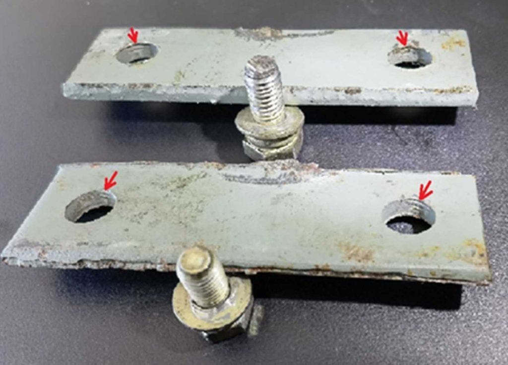
The three incidents of shear breakage of the fixing bolts of the axle baffle in the counterweight diverter pulley were collected by your author, as shown in Figure 5. Two of the three incidents involved a cast iron counterweight diverter pulley, and one involved a nylon counterweight diverter pulley. The damage of the rolling bearing in Figure 5 (a) is shown in Figure 6, and the obvious indentation in the baffle caused by the axle rotation of the diverter pulley in Figure 5 (a) is shown in Figure 7.
In the process of serious damage of rolling bearings, such as cage damage, ball breakage, sand and dust and other foreign-object intrusion, there is a certain probability of jamming or stuck failure mode. This failure mode led the counterweight diverter pulley to transmit a force to the pulley axle so that the original pulley axle will rotate and transfer the force to the baffle plates, as shown in Figure 7.
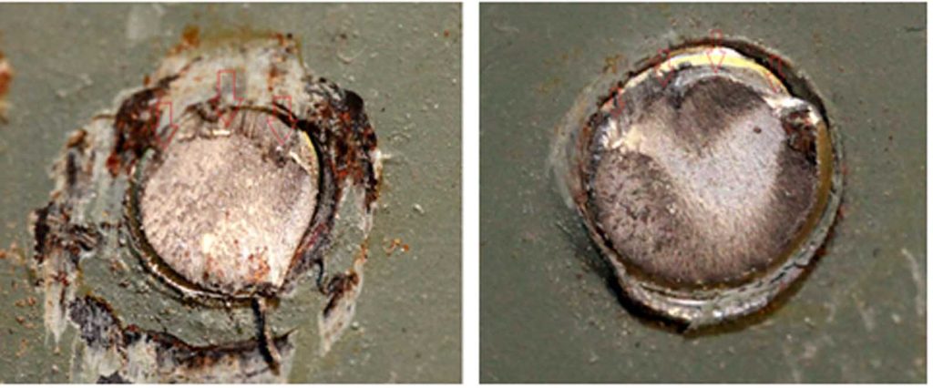
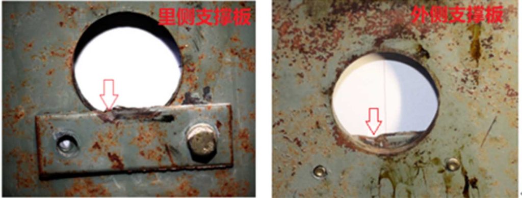
Figure 7 shows the obvious indentation of the diverter pulley axle baffle caused by the rotation of the axle. The axle baffle then transmits this force to the fixing bolt, causing the bolt to break, and the indentation of the bolt screw thread on the baffle plate hole is shown in Figure 14.
The elevator using the diverter pulley axle baffle design, under normal circumstances, may not consider the rolling bearing stuck failure mode. Its bolt strength is very weak; once stuck, the bolt shear break is inevitable. Figure 8 is the incident schematic diagram of the process of the rope disengaging from the counterweight. Figure 9 shows the incident deformation caused by the diverter pulley detaching from the support plate in the counterweight. Figure 10 shows anti-slack rope retainers cannot prevent the rope from escaping the rope groove after the rolling bearing is damaged.
2. Force Analysis and Calculation for the Fixed Bolts of Axle Baffle in the Counterweight Diverter Pulley Under the Condition of Bearing Stuck
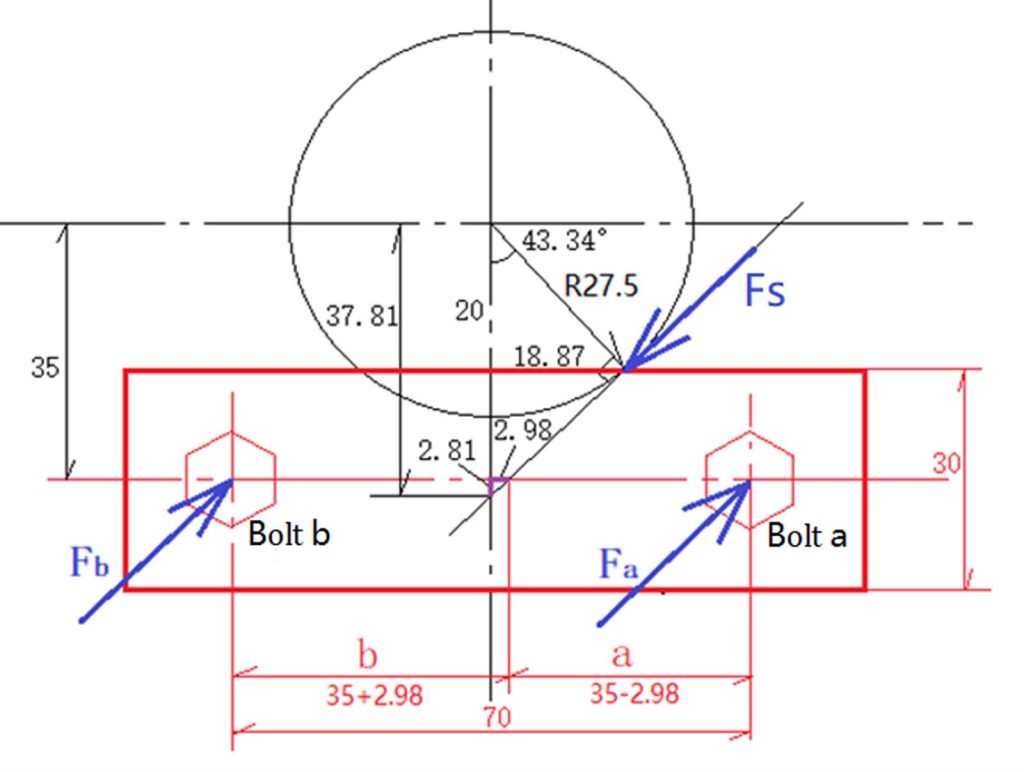
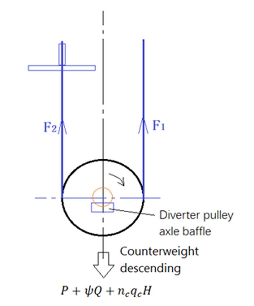
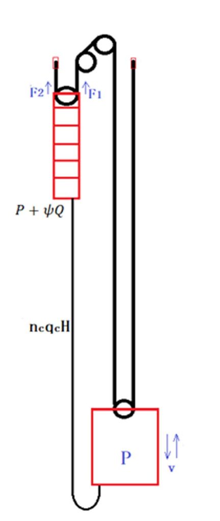
Considering that the slip of the rope on the pulley limits the tension difference of the rope on both sides of the pulley, the friction coefficient between the rope and nylon is μ=0.3 ~ 0.5 (nylon counterweight diverter pulley), and the shape parameter of the rope groove is as follows: β=0deg., γ=40deg.=0.698rad., calculating according to the traction force of EN 81-50:2014 5.11.2.3.1.1 as shown in Figures 11 and 12, the force calculation diagram of the two fixed bolts of the baffle plate, the equivalent friction coefficient between the rope and pulley:
The sum of wire rope tension: F1+F2=(P+ψQ+ncqcH)(g+a)
F1 and F2 are the tension of the wire rope on both sides (N); P is the mass of the unloaded car: 1700 kg; ψ is the balance coefficient: 0.48; Q is the rated load of car: 1000 kg; nc is the number of compensating chain: 2; qc is the mass per unit length of the compensating chain: 2.23 kg/m; H is the height of the counterweight in the well during the incident: 40 m Fr (N) is friction force between rope and pulley, Mr (Nm) is the friction torque between rope and pulley; and R (m) is the radius of pulley pitch circle.
Considering that when the bearing is stuck, the counterweight deceleration cannot be estimated; calculated according to the minimum value a=0, the greater inertial force is also limited by the rope wheel slipping in fact:
Shear stress calculation of two fixing bolts of baffle plate (Figure 13)
When μ=0.3, minimum shear stress:
Fixing bolt is M8, small diameter: d1=6.647, Bolt radius: r1=6.647/2=3.324 mm
Similarly, when μ=0.5, the baffle receives the maximum force
Fsmax:
Fsmax=62491N(Two baffle plates inside and outside)
According to the standard GB/T 3098.1-2020 4.8 class M8 bolt nominal tensile strength 400MPa. The calculated values of τamin, τbmin, τamax and τbmax are all greater than the nominal tensile strength 400 MPa of class 4.8 M8 bolts, and their shear strength values are lower than tensile strength.
According to the material test report from the incident, Tt is 17120N that the measured breaking strength of the M8 bolt of the baffle in counterweight diverter pulley form the incident, which is smaller than the calculated values of Famin, Fbmin, Famax and Fbmax.
Calculation result: When the bearing is stuck, the shear force of the two bolts is greater than the shear strength value. One of the bolts has to shear fracture. It should be noted that because the difference between τa and τb is not very large, which bolt (a or b) fails first depends on its strength, pre-tightening force and the gap with the baffle hole Φ9 in addition to the shear stress level.
Figure 14 and Figure 15 show photos of case (a) in Figure 5, where Figure 14 shows the shear fracture with obvious shear marks of the fixing bolt of the axle baffle in the counterweight diverter pulley, and Figure 15 shows the screw thread indentation of the axle baffle by the bolt.
Figures 5, 6, 7, 9, 10, 14 and Figure 15 can be consistent with the analysis and calculation in this article.
3. Reliability of Bearing Life Calculation
Rolling bearing design is generally calculated in accordance with 90% reliability of rolling bearing life, so its failure in the design life is foreseeable and unavoidable. In addition, elevator maintenance personnel cannot follow the counterweight frame to check the noise, vibration and temperature rise of its bearing rotation. Its fault detection is low, and serious damage is difficult to avoid.
If the required reliability of rolling bearings is increased from 90% to 98%, the a1 — life correction coefficient will drop from 1 to 0.33. That’s a 33% drop in life expectancy. That is to say, if the design life of the bearing is 15 years, it will be reduced to five years, and it is necessary to use higher-life bearings in design.
<Manual of Mechanical Design> (Chinese), Vol. 3, 5th Edition, Wen Bangchun, China Machine Press, P14-75
2.4.2 Calculation of revised rated life of rolling bearings
It is usually satisfactory to use the basic rated life L10 as the general criterion for selecting and evaluating the bearing life. This longevity is associated with 90% reliability, current materials and machining quality and conventional operating conditions.
Many use cases require a variety of different reliability, special bearing performance and operating conditions are not normal bearing life to calculate. In this case, you can use the following modified basic rated life calculation formula:
Lna=a1a2a3L10 (14.3-19)
Where Lna — special bearing performance and operating conditions, reliability of (100-n)% of the modified rated life (106 Rotations);
a1 — Life correction coefficient for reliability;
a2 — Special bearing performance life coefficient;
a3 — Life correction coefficient for operating conditions.
1) Reliability life coefficient a1, under normal circumstances is 90% reliability to assess the bearing fatigue life, then a1=1;
However, in some cases, the reliability is higher than 90%, which is the a1 coefficient. This can be selected according to Table 14.3-11.
4. Improvement Suggestions
As a part of the suspension system, the support structure of the counterweight diverter pulley will cause the car to fall due to the predictable single failure of the rolling bearing, and this failure mode has led to some serious incidents, which should arouse the attention of the elevator industry.
It is recommended to consider the diverter pulley rolling bearing stuck condition:
- The safety factor of the relevant force parts is above five in stuck condition, such as the use of baffle bolts, the shear safety factor is above five, or the reliability of the design life of the rolling bearing is increased to 98%.
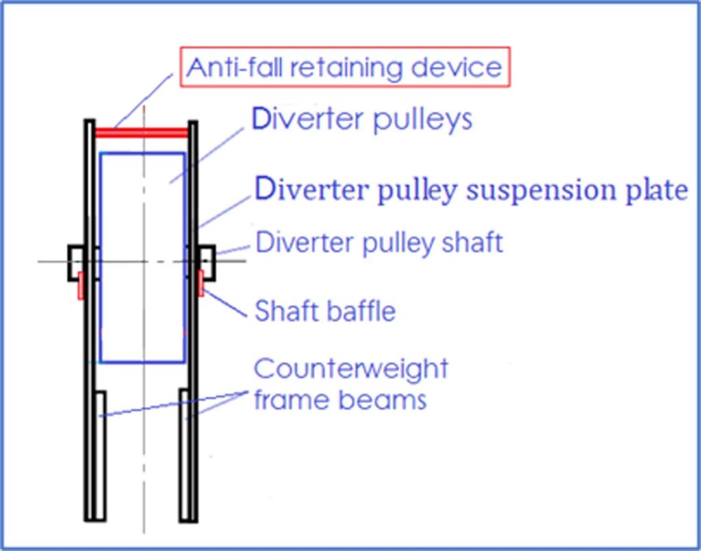
- The anti-fall retaining device is installed above the diverter pulley suspension plate or upper beam above the diverter pulley (Figure 16). Even if the diverter pulley is removed from the suspension plate or upper beam, the wire rope will be hung on the anti-fall retaining device and will not be removed from the counterweight. In addition, the anti-fall retaining device can also strengthen the deformation of the suspension plate or upper beam.
In fact, EN 81-20:2020 (E)/ISO 8100-1:2019(E) 5.5.8 already has this requirement, but it is not clear enough, and it is suggested that a clearer amendment could solve the problem:
EN 81-20:2020 (E)/ISO 8100-1:2019(E) 5.5.8 Original text:
5.5.8 Traction sheaves, pulleys and sprockets in the well
Traction sheaves, pulleys and sprockets may be installed in the well (Chinese elevator standard GB/T 7588.1-2020 translates “installed in the well” as “fixed in the well,” not include a pulley installed in the counterweight or car) above the lowest landing level under the following conditions:
a) there shall be retaining devices to prevent diverter pulleys/sprockets from falling in the event of a mechanical failure. These devices shall be able to support the weight of the pulley/sprockets and the suspended loads;
b) if traction sheaves, pulleys/sprockets are placed in the vertical projection of the car, then clearances in the headroom shall be according to 5.2.5.7.
Do these pulleys include pulleys installed in the counterweight or car?
My modification suggestion for EN 81-20:2020 (E)/ISO 8100-1:2019(E) 5.5.8:
“5.5.8 Traction sheaves, pulleys and sprockets in the well
All the traction sheaves, pulleys and sprockets installed in the counterweight, car or well shall meet the following conditions:
a) there shall be one or more anti-fall retaining devices to prevent suspension means, traction sheaves, pulleys or sprockets detaching from the counterweight, car or well in the event of a mechanical failure. These devices shall be able to support all suspended loads, the weight of the traction sheaves, pulleys or sprockets, to avoid the car, counterweight, traction sheaves, pulleys or sprockets falling down the well;
b) preserve the original text”


Get more of Elevator World. Sign up for our free e-newsletter.


