Anchoring Guide Rails under Seismic Conditions
Feb 1, 2017
A variety of design solutions are examined.
This paper was presented at  Madrid 2016, the International Congress on Vertical Transportation Technologies, and first published in IAEE book Elevator Technology 21, edited by A. Lustig. It is a reprint with permission from the International Association of Elevator Engineers
  (website: www.elevcon.com).
Specific design for seismic conditions is required in an increasing number of fields of construction. Cast-in steel plates connected to rebars before the concrete is poured are commonly used today for anchoring. Guide-rail brackets are welded to the steel plates. Up-to-date anchoring solutions for seismic conditions use either cast-in inserts connected to rebars or post-installed anchors. In each case, the rail brackets are fastened by bolts. The design of such anchoring systems follows North American and European standards for seismic conditions. This article provides an introduction to anchoring solutions for seismic conditions, plus the specific approvals and design approach required to comply with these approvals.
Now that appropriate building codes and construction regulations have significantly improved the strength and stability of structures with regard to earthquakes, there are increasing demands for seismic-resistant design to be used for anchor fastenings incorporated in non-structural elements of buildings. In addition to the major and moderately severe earthquakes that take place in the “classic” earthquake regions, with spectacular structural failures and reported accordingly in the media, smaller incidents occur regularly in many parts of the world.
Worldwide, the economic and social impact of the failure of energy or water supply systems and telecommunications or transport networks as a result of minor earthquakes reaches levels similar to, or possibly even exceeding, the costs and hardship resulting from the damage to or destruction of buildings and structures in locally severe earthquakes.
After a concrete structure has been built, work is carried out to install anchor points for structurally relevant elements, as well as for fastening structurally irrelevant components or equipment in or on the structure. These anchorages should be selected and designed in such a way that the cost of failure in the event of earthquakes of the expected magnitude is kept as low as possible. Even at the building planning and specification stage, corresponding consideration should also be given to nonstructural components to make the applicable general contractor and building inspectors aware of the requirements. Thus, it is not left up to the subcontractor to decide whether the corresponding provisions are to be made regarding the installation work.
Influence of Earthquakes
Earthquakes cause acceleration that leads to a very quick short-term increase in the forces acting on an anchorage. These forces are not only many times higher than when the structure is in a static state, their direction of action also changes rapidly. The anchorage must, thus, be capable of taking up dynamic loads. Standards for anchorages of this kind have existed for several years.[3] However, the cracks that appear in concrete as a result of earthquakes are considerably larger than the crack width of 0.3 mm taken into account in the standards for anchors set in the tension zone of cracked concrete.
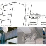
Due to extremely plastic deformation of the structure of a building, especially in the area of nodes in the structure that act as flexible joints, cracks with a width of several millimeters may appear. Anchors of the types currently in use are not designed to continue to function in cracks of this width and are, therefore, subject to failure. Accordingly, planning should ensure that anchorages in structures that may be exposed to earthquakes are not positioned in the proximity of the flexible nodes of the structure.
Mechanical expansion anchors installed with a controlled preset tension (torque controlled) and with the ability to very quickly apply subsequent additional expansion in the event of an increase in hole diameter due to cracking are generally suitable for use in reinforced concrete in which the formation of large cracks is to be expected as a result of earthquakes. Anchors that transfer forces to the concrete by forming a keyed hold, as is the case with undercut anchors, are also suitable.
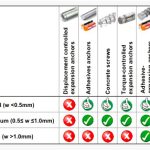
Certain types of chemical anchors have also proved suitable for use in concrete components subjected to earthquakes. Likewise, anchor channels connected to the reinforcement before the concrete is poured (also known as “cast-in”) are capable of transferring forces to the concrete structure by way of a keyed hold. Table 1 provides an approximate assessment of the suitability of current anchor types for seismic loading. The performance of the anchors depends greatly on the width of the cracks resulting from the effects of earthquakes. This classification is based on a general assessment and not on the results of special tests of individual anchor types in accordance with current seismic suitability test standards.
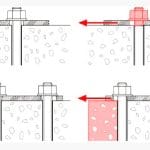
In addition to the tensile forces that occur due to high acceleration of a structure, shear forces also rise to a level many times above that for which the anchorage was designed. When this happens, the cohesive friction creating stability between the base plate of the fastened structure and the surface of the concrete is exceeded, and the annular gap between the anchor shank and perimeter of the hole allow movement of the structure up to the point at which the anchor shank comes into contact with the edge of the hole, resulting in a positive hold (Figure 3a).
Due to the rapidly changing direction of the forces, this process can recur in several directions. If a base plate is fastened by several anchors, this usually means that only some of the anchors are capable of providing a positive hold and that the entire load is then carried by these anchors. The dynamic loading and extremely high peak forces lead to failure of the anchors or failure of the concrete when these anchors carrying the shear load by way of their positive hold are positioned close to the edge of a concrete member (Figure 3b). Movement can be avoided and the shear load distributed among all of the anchors that make up the anchorage if the annular gap between the anchor shank and perimeter of the hole is suitably filled. For this purpose, anchor manufacturers have developed special washers with apertures that allow adhesive anchor mortar, which cures without shrinkage, to be injected into the annular gap. These systems form an integral part of the European standards for the design of anchorages for use where seismic influences are to be expected.
Research on Seismic Effects
Until only a few years ago, little was known in detail about the effects of earthquakes on post-installed anchor points on concrete structures. For this reason, where steel is to be anchored to concrete, standard practice today requires that anchorages to be subjected to seismic action are installed by welding the required parts to the steel reinforcement. This is done by incorporating cast-in steel plates in the reinforced-concrete structure. These plates are exposed on the surface of the concrete at the required fastening positions. If fastenings of this kind are not taken into account at the planning stage or are forgotten before the concrete is poured, concrete subsequently has to be chipped away to expose the rebars.
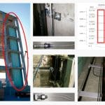
In the meantime, a research program allowing comprehensive and detailed investigation of the stressing of nonstructural components and equipment installed in buildings exposed to earthquakes has been carried out by various universities in the U.S. over a period of several years. For this purpose, a five-floor reinforced-concrete building structure was erected on the world’s biggest freestanding shaker table at the Englekirk Structural Engineering Research Center at the University of California, San Diego (UCSD).
Functioning systems for the supply of energy and water, heating, air conditioning and telecommunications, as well as the equipment required in hospital intensive-care units and operating theaters, were installed on the various floor levels of the building. The floors were connected by a steel stairway and a functioning elevator. Up to 40 companies from the associated industries have supported the project. Hilti products and systems were used for anchorages.
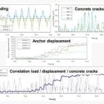
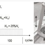
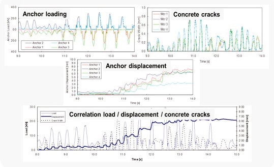
In April and May 2012, the building was subjected to shocks simulating the measurements obtained from the most violent earthquakes experienced in recent years. The shaker table was used to simulate seismic events with a magnitude of 6.7, such as those registered at Northridge, California, in 1994, up to earthquakes with a magnitude of 8.8, like the one experienced in Chile in 2010. The behavior of the building and the loads to which the installed equipment was subjected during the simulation were recorded by a global positioning system, more than 80 digital cameras and up to 500 sensors installed in the building. The results have been used to confirm and optimize the American and European standards for the design and selection of seismic-resistant anchor systems for use on concrete structures.
U.S. and European Seismic Regulations
Correct design and selection of an anchorage for use on an existing concrete member begins with the definition of the forces that will be acting on it. In the U.S., the procedure for the definition of the forces to be expected as the result of an earthquake is based on American Society of Civil Engineers (ASCE) 7, while determination of the performance of an anchor under seismic influence is based on American Concrete Institute (ACI) 318, Appendix D for mechanical anchors and ACI 308 for chemical anchors. The technical documentation (ICC Evaluation Service report) prepared based on the test standards and approval criteria mentioned above provides a sound foundation for the correct design and selection of the anchorage.
The European standard takes the same approach. In this case, the forces acting during earthquakes are defined in EN 1998:2004 (Eurocode 8). Until EN 1992-4 comes into force, which was expected by the end of 2016, the standard for the design and selection of earthquake-resistant anchorages for steel structures on concrete is laid down by the European Organisation for Technical Approvals (EOTA) TR 045. This technical guideline is aligned with European Technical Approval Guidelines (ETAG) 001 Annex E, which defines the testing and determination of performance data for anchors under seismic stressing and provides documentation of this in ETA reports. European standards for the design of an anchorage for use on existing concrete components exposed to seismic stress are, thus, well coordinated.
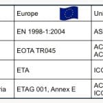
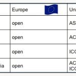
Table 2 provides an overview of how the guidelines and standards mentioned are applied. The design guidelines presented here represent the current state of the art for the testing and design of anchorages under the influence of seismic action. Virtually all of the countries of the world base their regulations on the design of earthquake-resistant anchorages on one of these two standards.
Seismic Load Definition
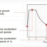
The starting point for the definition of seismic actions is the seismic design spectrum. In the U.S., a seismic design category (SDC) has been endorsed, and the seismic design spectrum is obtained from the mapped maximum (short period, 0.2 s.) and 1.0-s. period acceleration. In Europe, however, the seismic hazard is defined by the peak ground acceleration, and no SDC has been established. There is, however, a clear definition of low and very low seismicity based on the design ground acceleration, and, in the case of very low seismicity, no specific seismic provisions need to be observed.
The influence of the soil type is given consideration in both codes by a site coefficient, which is based on matching ground classifications, taking the shear wave velocity limits and soil descriptions into account. Based on the risk of possibly improper seismic performance, the categorization of buildings is carried out in the same way by both codes, and the correspondent importance factor is assigned with similar values (although at a different phase of the design flow).
Considering the points mentioned above, the equations used to derive the seismic design spectrum are expected to differ between codes, but, when equivalent importance classes and ground types are considered, the resulting shape and spectral acceleration are very similar. In simple terms, it can be said that, mathematically, the two codes just point to different coordinates of the design spectrum. Please note that the design response spectrum, in accordance with ASCE 7, does not take the importance of the building into account (this is taken into consideration in the design later), and, consequently, the comparison was made by taking the resulting spectrum into account, scaled accordingly by this factor.
A comparison was also established between the seismic base shear force using EN 1998-1:2004 and the ASCE 7. By evaluating the different expressions, as well as some practical applications of the codes, we can conclude that the values are decidedly coincident. Working from the seismic base shear force, various well-known methods can be used to determine the load acting at each level of the structure.
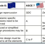
Accordingly, by comparing the resulting seismic design spectrums with equivalent importance classes and ground types (S being the soil factor), it is possible to correlate the European seismicity rating with the U.S. seismic design category.
The only, yet important, exception to Table 3, in the case of a building of importance class IV and a seismicity rating of low or above the corresponding seismic design category, is C or above. This means that in cases where buildings could pose a substantial hazard to the environment or community in the event of failure (e.g., hospitals, fire stations, power plants), the design should take all seismic-specific provisions into account.
Anchor Seismic Design Resistance
Provisions for seismic anchor design are provided by ACI 318 Appendix D or the recent EOTA TR 045. Both design regulations work with the concrete capacity (CC) method to calculate the characteristic resistances of fastenings. Differences between the codes occur in the basic assumptions for the design equations, which partially result in different factors. According to the CC method, the design resistances are calculated for tensile loading and shear loading, taking all possible failure modes into account.
All of the safety concepts discussed here calculate resistance and actions based on partial safety factors. The main requirement for design using the codes discussed is that the factored action E shall be less than or equal to the factored resistance R (Equation 1). All codes factor the characteristic action Ek with partial safety factors γ (Equation 2).
Ed ≤ Rd (Equation 1)
Ed = Ek ∙ γ (Equation 2)
For the characteristic resistance, there is a conceptual difference, since the European codes divide the characteristic resistance Rk by a partial safety factor γ (Equation 2.3), whereas U.S. codes calculate the characteristic resistance Rk with a strength reduction factor γ (Equation 2.4). The effect of these factors, however, is the same: reducing the characteristic value to design level. The design resistance Rd is generally very similar for all the evaluated failure modes irrespective of the code adopted.
Rd ≤ Rk / γ (3)
Rd = Φ ∙ Rk (4)
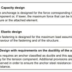
As per the new European EOTA TR045 design guideline, design incorporates three approaches, which are described below. Note that all three of these design approaches are acceptable within their application conditions. Table 4 provides an overview of these different design options.
Note that ACI 318 also considers three design approaches that are conceptually the same as the ones presented by EOTA TR 045. The main difference, which nevertheless has the same background intention, comes from the fact that the “elastic design” defined as per European guideline takes a different approach in U.S. regulations. In ACI 318, this design option takes the loads resulting from a regular seismic design (not elastic) into account and introduces a reduction factor (recommended as 0.4) that is to be directly applied to all concrete failure modes.
Evaluation of Anchor Seismic Performance
Three different basic guidelines must be considered for the testing of fastenings in concrete. In the U.S., ACI 355.2 covers the testing of post-installed mechanical anchors under static and seismic loading and prescribes testing programs and evaluation requirements for post-installed mechanical anchors intended for use in concrete under the design provisions of ACI 318. This guideline forms the basis for acceptance criteria (AC) 193 and AC 308 by the International Code Council (ICC). While AC 193 covers the testing of mechanical anchors, AC 308 covers the testing and design of adhesive anchors.
With regard to the main testing procedures, the anchors are installed in a closed crack that is then opened to a width of 0.5 mm. The anchors under test are then subjected to the specified sinusoidal varying loads using a loading frequency of between 0.1 and 2 Hz. The maximum seismic tension and shear test load is equal to 50% of the mean capacity in cracked concrete from reference tests.
After the simulated seismic tensile loading and seismic shear loading cycles have been run, the anchors are then tested to failure under static tensile and static shear loading. The mean residual tension and shear capacities are to be assessed in accordance with the limits defined in the guideline.
In Europe, ETAG 001 is applicable for the testing of post-installed mechanical (parts 1-4) and bonded anchors (part 5). The seismic pre-qualification of anchors has been regulated in Europe since the release of ETAG 001 Annex E in the first half of 2013. Two different testing programs are presented to assess the anchor’s suitability for seismic loading, resulting in two seismic performance categories, as follows:
Seismic category C1: Similar to the U.S. seismic pre-qualification procedure and only suitable for non-structural applications.
Seismic category C2: Very demanding seismic crack movement test for classification of an anchor as suitable for structural and non-structural applications.
While seismic category C1 is identical to the U.S. seismic pre-qualification procedure, seismic category C2 involves a set of considerably more demanding seismic load and/or crack-cycle tests, especially considering that for assessment of seismic performance under tensile loading, one of the tests involves cycling of the cracks up to a width of 0.8 mm.
In practical terms, according to EOTA TR045 and for ag∙S above 0.05 g, anchors intended for connections between structural elements of primary or secondary seismic members should always comply with seismic category C2. For anchors used for the attachment of non-structural elements where the acceleration ag∙S is between 0.05 and 0.10 g, items of the seismic category C1 can be used. Please note that these are generic recommendations that member states can adjust locally.
U.S. and European Seismic Regulations for Cast-In Anchor Channels
Much less detailed information is available regarding the behavior of cast-in anchor channels under the influence of seismic action than for post-installed anchors in concrete. In the same way as post-installed anchors in concrete, standards and regulations have been applicable in the U.S. since October 2015 regarding the design and selection of cast-in anchor channels for seismic loading applications.
ASCE 7 bases the approach for definition on the forces expected as a result of the effects of seismic action. The performance of a cast-in anchor channel under earthquake influence should be determined on the basis of AC 232, Appendix A, approved in October 2015, and ICC Evaluation reports, respectively. The performance data (ICC-ES reports) prepared on the basis of the test standards and approval criteria mentioned here provides a sound foundation for the correct design and selection of the anchorage.
Conclusions
Comprehensive guidelines and standards exist in the U.S. and in Europe for the design and selection of earthquake-resistant anchorages on concrete consisting of post-installed anchors. While such standards also covering cast-in anchor channels have been enforced in the U.S. since October 2015, Europe is still working towards this goal. Engineers and planners can now orient themselves towards these standards and guidelines when specifying earthquake-resistant anchorages for use on concrete.
Manufacturers of post-installed anchors and cast-in anchor channels for use on concrete are now responsible for ensuring that their products are tested on the basis of the standards and guidelines for the testing of such anchorages under seismic stressing and that the corresponding technical documentation is drawn up or, alternatively, that new products in compliance with these standards are developed.
Hilti has played a pioneering role in the cooperative effort towards preparation of seismic standards, as well as the development of suitable products and the production of the appropriate technical documentation. ETA approvals for seismic category C2 have already been obtained for Hilti’s HIT-HY200 chemical anchor system in conjunction with HIT Z anchor rods, as well as for HST mechanical anchors. As of early 2016, Hilti HAC anchor channels, in conjunction with Hilti HBC-C channel bolts, are the only products available on the market for which technical performance data for the design and selection of anchorages exposed to seismic action in accordance with AC 232 have been made available in an ICC-ES report.
- Figure 1: World seismic stations, 2006
- Figure 2: Locations to avoid in seismic anchoring
- Figure 3: Movement in annular gap changes stress distribution if friction fails
- Figure 4: Seismic research at UCSD 2012
- Figure 5: Results of evaluation at UCSD 2012
- Figure 5: Results of evaluation at UCSD 2012
- Figure 6: Design response spectrum according to Eurocode 8 and ASCE 7
- Table 1: Seismic suitability of anchor types
- Table 2: Seismic design framework for post-installed anchors on concrete
- Table 3: Eurocode 8 seismicity rating compared to ASCE 7 SDC for building importance class I, II and III
- Table 4: Seismic design options per European seismic guideline
- Table 5: Seismic design framework for cast-in anchor channels in concrete
References
[1] 2nd European Conference of Earthquake Engineering and Seismology, Istanbul 2014.
[2] Gramaxo, J., Ural, M., New European Seismic Regulations for the Qualification and Design of Post-Installed Anchoring, Elevcon 2006: Elevator Technology 16.
[3] Merz, M., Dynamic Design for Elevator Anchoring to Buildings, 2006.
[4] American Concrete Institute, AC232, Acceptance Criteria for Anchor Channels in Concrete Elements, 2015.
[5] ICC Evaluation Service, Inc., AC232, Acceptance Criteria for Anchor Channels in Concrete Elements, 2015.
Get more of Elevator World. Sign up for our free e-newsletter.

