Articulated Funiculator: The Sky Subway
Aug 1, 2013
by Fritz King, Mats Lundström, Sirpa Salovaara and Peter Severin
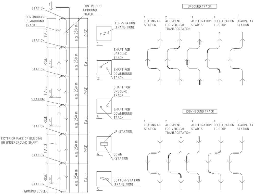
As building heights increase, so do the number of lifts, lift shafts, associated energy usage and passenger wait and travel times. The loss of rentable/sellable floor space and escalating energy costs challenges the viability of high-rise buildings. This article explores a new and innovative solution to vertical transportation, the articulated funiculator. The articulated funiculator is a continuous and connected system of “trains” that moves people en masse – a “Sky Subway.” The trains lie horizontally at specific floor levels designated as “stations” and transition from horizontal to vertical alignments between the stations, albeit the train cars and passengers remain horizontal in a standing position. The articulated funiculator captures the energy from the braking of the trains and stores it. The stored energy is then used to accelerate the articulated funiculator. The articulated funiculator requires only two vertical shafts, decreases the amount of conventional lifts, increases rentable/sellable floor-space percentages, reduces wait and travel times and is sustainable.
Vertical Living: A Fact of Life
The number of high-rise buildings has tripled in the past 30 years. In 1982, the amount of completed high-rise buildings was 2,091; in 1992 it was 3,048; in 2002 it was 4,306; and there were 7,409 in 2012. The number is increasing rapidly all over the world.[1]
The world has experienced unprecedented urban growth in recent decades. In 2008, for the first time, the world’s population was evenly split between urban and rural areas. There were more than 400 cities with more than 1 million inhabitants and 19 cities with more than 10 million dwellers. Developed nations were about 74% urbanized, while 44% of the inhabitants of less-developed countries lived in urban areas. However, urbanization is occurring rapidly in many less-developed countries. It is expected that 70% of the world population will be urbanized by 2050, and most of that urban growth will occur in less-developed countries.[2]
In 1950, 79% of the population of the U.K. lived in cities – already a large figure, but one which is set to rise to 92.2% by 2030. Elsewhere, China’s percentage rose from 13% to 40.4% between 1950 and 2005 and is predicted to rise to 60.3% by 2030. But it’s Botswana that has experienced the largest influx. Next year, 61.2% of its population is expected to live in urban areas, yet back in 1950, only 2.7% of Botswanans lived in cities.[3]
In China and South East Asia, many mega cities are being built, and the number of skyscrapers is constantly increasing: vertical living is and will continue to be a fact of life. Efficient high-rise buildings that save energy and space are in demand more than ever before. The articulated funiculator and the tubed mega frame provide one solution to meet this growing demand.
Rethinking Vertical Transportation
The skyscraper was born with the invention of the lift in the 1850s and the electric lift in 1880s. The concept of transporting people and goods between floor levels was innovative and propelled the development of the skyscraper. As buildings grew in height, so did the number of lifts and the concept of grouping the lifts into a central lobby was introduced.
Banking lifts improved efficiency and reduced wait times. Lift speeds increased over time, but the original concept of a single box inside a vertical shaft remained the same. In tall and supertall buildings, this concept of vertical transportation requires many lifts and shafts, and this demand diminishes the amount of leftover rentable/sellable floor space. This drawback is compounded by longer wait/travel times and higher energy consumption. It appears that as the height of buildings increases, the current concept of vertical transportation needs to be rethought.
It is apparent that tall and supertall buildings are analogous to vertical cities. In a horizontal city, it is common to have residences, offices, hotels, shopping malls, movie theaters, hospitals and the like, and it is common and logical to use buses and subways as a means of transportation. The same logic and common sense applies to vertical cities, and if lifts are buses, the articulated funiculator is the subway.
| Name | City | Height (m) | Floors | Completed | Total number of elevators | Top elevator speed (mps) | Building width (m) | Core width (m) | Floor plate (m2) | Core area (m2) | Usable FAR | Building slenderness factor |
| Ping An Finance Center | Shenzhen, China | 660 | 115 | 2015 | 76 | 10 | 56 | 30 | 2925 | 964 | 0.670 | 1/12 |
| Shanghai Tower | Shanghai | 632 | 121 | 2014 | 106 | 18 | 65 | 30 | 2463 | 996 | 0.596 | 1/10 |
| Chicago Spire | Chicago | 610 | 150 | – | – | – | 60 | 28 | 2400 | 975 | 0.594 | 1/10 |
| Taipei 101 | Taipei | 508 | 101 | 2004 | 61 | 16.8 | 56 | 30 | 3190 | 1084 | 0.660 | 1/9 |
| Shanghai World Financial Center | Shanghai | 492 | 101 | 2008 | 91 | 10 | 58 | 30 | 3334 | 882 | 0.735 | 1/9 |
| International Commerce Centre | Hong Kong | 484 | 108 | 2010 | 83 | 9 | 52 | 28 | 2555 | 792 | 0.690 | 1/10 |
| Petronas Towers | Kuala Lumpur | 452 | 88 | 1998 | 39 | 7 | 56 | 23 | 2356 | 600 | 0.745 | 1/8 |
| Jin Mao Tower | Shanghai | 421 | 88 | 1999 | 61 | 9 | 54 | 27 | 2356 | 602 | 0.744 | 1/8 |
| Two International Finance Centre | Hong Kong | 412 | 88 | 2003 | 62 | 10.6 | 55 | 26 | 2196 | 675 | 0.693 | 1/8 |
| CITIC Plaza | Guangzhou, China | 390 | 80 | 1996 | 36 | – | 47 | 24 | 2190 | 598 | 0.727 | 1/8 |
Articulated Funicular Concept
The articulated funiculator (Figure 1) is a series of trains separated by some distance – for example, every 250 m. The trains lie horizontally at specific floor levels designated as “stations.” The trains transition from horizontal alignments at the stations to vertical alignments between the stations, albeit the passengers remain in a standing position. The trains ascend and descend on tracks that snake from one side of the building to the other. As shown in Figure 1, as the up-bound tracks traverse right, up and left; the down-bound tracks traverse left, down and right. The tracks transition together at the bottom and top of the building and make a continuous loop. The articulated funiculator stops at all up- and down-bound stations simultaneously, unloads and loads passengers, and proceeds up and down to the next stations. Intermediate floors between stations are serviced by conventional lifts.
Train Concept
The articulated funiculator is a series of trains made of train cars that house the passenger carriages and carriage frames. The articulated funiculator is designed so the passengers remain standing, even though the train alignment transitions from horizontal to vertical. This means the carriages will need to pitch inside the carriage frames. In addition, the articulated funiculator needs to move in such a way as to allow for the transition alignments at the tops and bottoms of buildings.
Movement studies of the transitions at the top and bottom of the buildings (Figure 2) shows a passenger carriage could experience rotation around three axes: pitch, roll and yaw (Figure 3). The motion study concludes: 1) the carriages will need to pitch in order for the passengers to remain standing, 2.) the carriages will need to roll and yaw to facilitate the transition in the curved portion of the alignments and 3.) the carriages will need to (only) roll to facilitate the transition in the vertical portions of the alignments. The concept to facilitate these motions is to have a cube-shaped (cuboid) passenger carriage inside a spherical carriage frame. A cuboid carriage could pitch, roll and yaw inside a spherical frame.
It seems simpler to implement the transition motion in the vertical portions of the alignments, rather than in the curves. This eliminates the need for the carriages to yaw. It also makes sense to take the roll motion between the train cars, instead of in the carriages. This could be done with coupling mechanisms between the train cars that swivel. The result is a train with barrel-shaped carriage frames with cuboid carriages (Figure 3). The natural progression is to form and shape the trains for aerodynamics to reduce drag (Figure 4). Each train car has eight sets of wheels and rolls on four tracks.
A carriage frame height and width of 2.2 m results in a carriage frame diameter of 3.11 m based on geometry, and a total carriage frame outer diameter of 3.5 m is shown. A total frame length of 3.5 m is also shown and results in a square train cross-section.
Movement Strategies
Pitch and roll requirements for single-, double- and triple-loop configurations are shown in Figure 5.
Acceleration and Velocity Strategies
The recommended fastest acceleration on the vertical legs is 1 g. This would result in a 0-g environment on the fall accelerations and rise decelerations, and a 2-g environment on the fall decelerations and rise accelerations (Figure 6). Accelerations greater than 1 g would “separate” the passengers from the floors and necessitate restraints. With 1-g accelerations and decelerations, it would take 10.1 s. to traverse the 250 m between the stations in our example, and the train would reach a maximum speed of 178 kph. Figure 6 shows minimum times and maximum velocities for a range of rise/fall lengths. It is obvious a 1-g environment would exceed the comfort level of some passengers, so studies to determine the maximum usable acceleration would need to be conducted.
The cycle time between trains can be approximated for the 250-m example. It is estimated that unloading and loading of the trains at the stations could take 20-30 s. It would also take about 5 s. for the trains to move from the stations and position vertically before the rise/fall accelerations. This, plus the 10-s. rise/fall, adds up to an estimated cycle time of 1 min. between trains at peak usage times. Train movements and cycle times can be reduced for off-peak times.
Power/Braking Cogs
The articulated funiculator is a series of trains connected with cables. The cables span between the trains and are looped around cogs, where the alignments transition from horizontal at the stations to the vertical rises/falls (Figure 7). The cogs attach to the cables and serve to both brake and power the system. The cogs are connected to generators/motors that will capture energy while braking and power the system while driving.
Dynamic Braking, Energy Storage and Power Extraction
When the down-bound payloads are heavier than the up-bound ones, the articulated funiculator captures the energy from braking the trains (dynamic braking) and stores it. The stored energy is then used to accelerate the articulated funiculator when the up-bound payloads are heavier than their down-bound counterparts. The capture and reuse of energy makes the articulated funiculator sustainable. For example, as lunchtime approaches, most passengers will travel down the building, and the energy needed to brake the articulated funiculator will be stored and used to power passengers back up the building after lunch.
Prototype Building
To further explain the articulated funiculator, a prototype building and its superstructure are shown (Figure 8). The building’s plan dimensions are 40 X 45 m, with a height of 620 m (about 120 floors). This configuration has a slenderness factor of 1/15.5 in the short and 1/13.8 in the long direction. The building has four articulated funiculator stations, one at ground level, one at an elevation of 168 m, one at an elevation of 353 m and one at an elevation of 538 m.
| Rise/Fall (m) | Time (s.) | Maximum Velocity (kph) |
| 200 | 9.03 | 159 |
| 225 | 9.58 | 169 |
| 250 | 10.10 | 178 |
| 275 | 10.59 | 187 |
| 300 | 11.06 | 195 |
| 350 | 11.95 | 211 |
| 400 | 12.77 | 225 |
| 450 | 13.55 | 239 |
| 500 | 14.28 | 252 |
Station Concept
The stations for the articulated funiculator are 10 m wide (wall centerline to wall centerline) and three stories deep (Figure 9). Passengers enter and exit the trains from the middle story. From there, passengers have access to escalators to take them either up one floor (where they can reach lifts to take them up) or down one floor (where they can reach lifts to take them down). Doors through the stations on the upper and lower floors provide access to the opposite side of the building. The cogs and the generators/motors will be housed inside the stations.
Structural Compatibility
The articulated funiculator lends itself to an efficient structural system well adapted to tall, thin skyscrapers and high-strength concrete. It makes sense to use the vertical corridors that house the articulated funiculator as the superstructure, which is common with central cores. The vertical legs are 6 m wide (wall centerline to wall centerline) and 10 m long. This gives 8.5 X 4.5 m inside clear dimensions (1.5-m-thick walls) and fits the 3.5- by 3.5-m train cross-sections. It also makes sense to use the horizontal stations as the superstructure, which is common with outriggers. The combination of the vertical and horizontal tubes forms a tubed mega frame. Mega cross tubes are placed at intermediate elevations between the stations and at the top of the building for structural performance. These intermediate cross tubes are at the following elevations: 78, 264, 449 and 615 m. The same structural system is used in the perpendicular direction, and the symmetry gives rise to the 3D tubed mega frame (Figure 8). All the floor loads are transferred to the four vertical legs at station and outrigger levels with diagonals.
The length of the articulated funiculator is a function of the number of cars in the trains. This length sets the minimum width of the building in the direction of the stations and locates one set of the vertical legs of the tubed mega frame.
The tubed mega frame lends itself to a variety of floor-plate shapes and sizes. Figure 10 illustrates three generic shapes and tabulates usable floor-space ratios. The articulated funiculator occupies half the area of two of the vertical legs, and it is expected the other half of these shafts will be used as duct space. It makes sense to house the conventional lifts, stairs and ductwork in the remaining two legs. Placing all of the vertical transportation and ductwork inside the four legs of the structure leaves the rest of the floor plate completely open and results in high usable floor-space ratios.
| Floor plate | Length (m) | Width (m) | Floor plate (m2) | Core area (m2) | Ratio |
| A | 40 | 40 | 1,600 | 308 | 0.808 |
| A | 45 | 40 | 1,800 | 308 | 0.829 |
| A | 45 | 45 | 2,025 | 308 | 0.848 |
| A | 40 | 50 | 2,000 | 308 | 0.846 |
| A | 45 | 50 | 2,250 | 308 | 0.863 |
| A | 50 | 50 | 2,500 | 308 | 0.877 |
| B | 40 | 40 | 1,180 | 308 | 0.739 |
| B | 45 | 40 | 1,310 | 308 | 0.768 |
| B | 45 | 45 | 1,450 | 308 | 0.787 |
| B | 40 | 50 | 1,435 | 308 | 0.785 |
| B | 45 | 50 | 1,560 | 308 | 0.806 |
| B | 50 | 50 | 1,740 | 308 | 0.823 |
| C | 40 | 40 | 1,420 | 308 | 0.783 |
| C | 45 | 40 | 1,560 | 308 | 0.802 |
| C | 45 | 45 | 1,780 | 308 | 0.827 |
| C | 40 | 50 | 1,700 | 308 | 0.819 |
| C | 45 | 50 | 1,930 | 308 | 0.840 |
| C | 50 | 50 | 2,175 | 308 | 0.858 |
Vertical-Transportation Plan
The vertical-transportation plan is a combination of one articulated funiculator with three loops and four stations, and conventional lifts that run between the stations (Figure 11). Passengers have three options for movement. They can ride the articulated funiculator to a station and take conventional lifts up, ride the articulated funiculator to a station and take conventional lifts down or ride the conventional lifts. The third option may require a transfer from one lift run to another. It is expected that these multiple movement options will increase the volume of passenger flow and reduce congestion.
There are 35 inhabitable floors and two mechanical floors, with 160 m between stations. It is, therefore, expected that about six lifts will be needed between the stations and four above the highest station. This results in a total of 22 lifts for the building.
Structural Performance
The tubed mega frame is an efficient structure, because almost all of the loads are carried by the four vertical legs set at the exterior faces of the building.
The superstructure has seven vertical zones, and the wall thicknesses step from 1.5 m at the base to 0.3 m at the crown. Structural analysis runs using ETABS integrated building-design software and a wind speed of 83 mph (37.1 mps) indicate a concrete strength of 60-70 MPa with minimal reinforcing ratios is required.
The first five modes’ shapes and periods are shown in Figure 12. Mode 1 is in the 40-m direction, mode 2 is in the 45-m direction, mode 3 is in the 40-m direction, mode 4 is in the 45-m direction, and mode 5 is twisting.
Wind speeds of 77.5 mph (34.6 mps) result in maximum inter-story drift ratios of about H/360 in the 40-m direction and H/540 in the 45-m direction using a modulus of elasticity of 50 GPa.
Architectural Programs
The removal of the central core creates the potential for new and exciting programs that have not yet been incorporated into tall, thin skyscrapers. Because the floor plates are open, it is possible to program concert halls, conference rooms, theaters and swimming pools into the body of the building.
The tubed mega frame offers flexible architectural configurations and can support many forms and shapes (Figure 13).
Conclusion
Vertical living is and continues to be a fact of urban life; thus, efficient and sustainable solutions for tall, thin skyscrapers are needed. The goal of the articulated funiculator and the tubed mega frame is to increase efficiency and sustainability and assist in the development of tall, thin skyscrapers. The articulated funiculator and the tubed mega frame offer:
- Reduced number of lift shafts
- Reduced number of lifts
- Increased speed of passenger conveyance
- Reduced vertical-transportation energy costs due to energy capture and reuse
- Increased rentable/sellable FARs
- Reduced real-estate costs due to smaller floor-plate sizes at the base of the buildings
- An efficient structural system that can support slenderness ratios of 1/15.5
High speeds, large passenger volumes and recyclable energy make the articulated funiculator the way of the future. It is time for a new generation of lift systems to take a step forward!
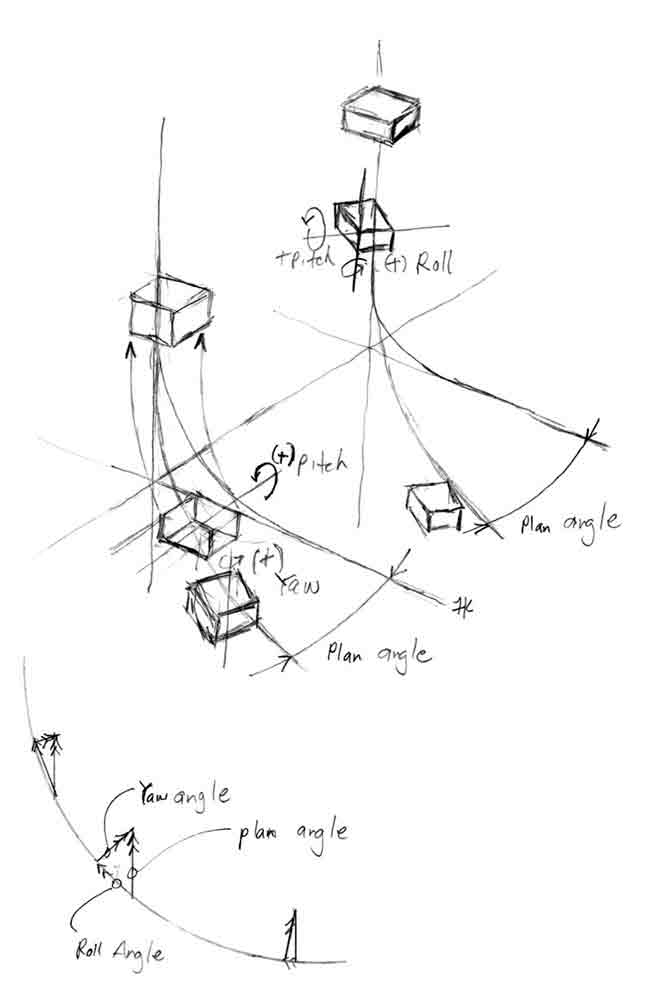
Figure 2: Movement study of the transitions 
Figure 3: Articulated funiculator pitch, roll and yaw diagrams 
Figure 4: Articulated funiculator train concepts 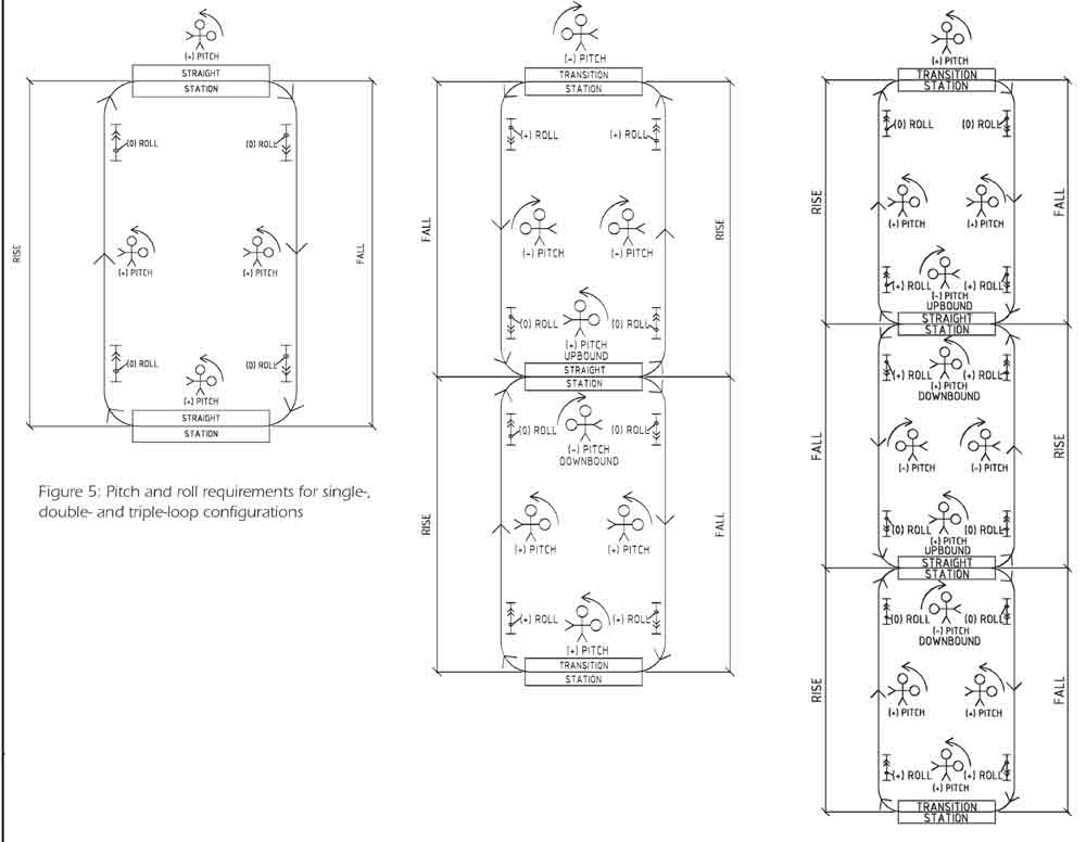
Figure 5: Pitch and roll requirements for single-, double- and triple-loop configurations 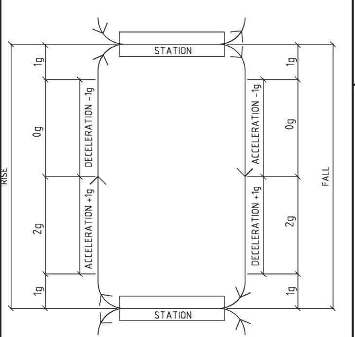
Figure 6: Accelerations, velocities and time strategies 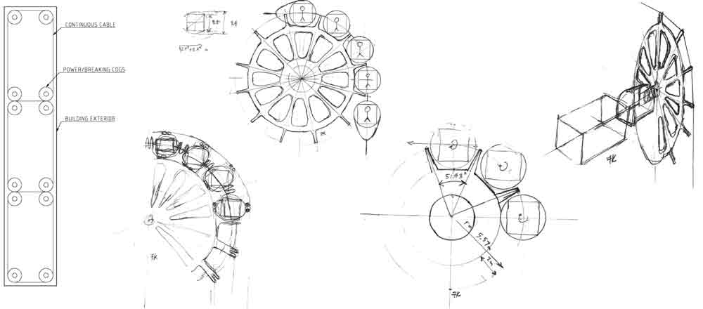
Figure 7: Power/braking cogs 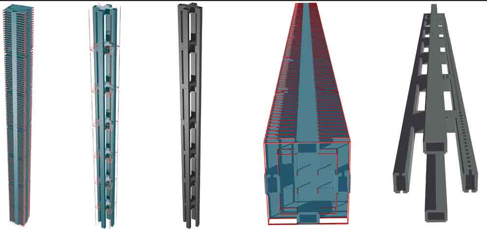
Figure 8: (l-r) Prototype building and its superstructure 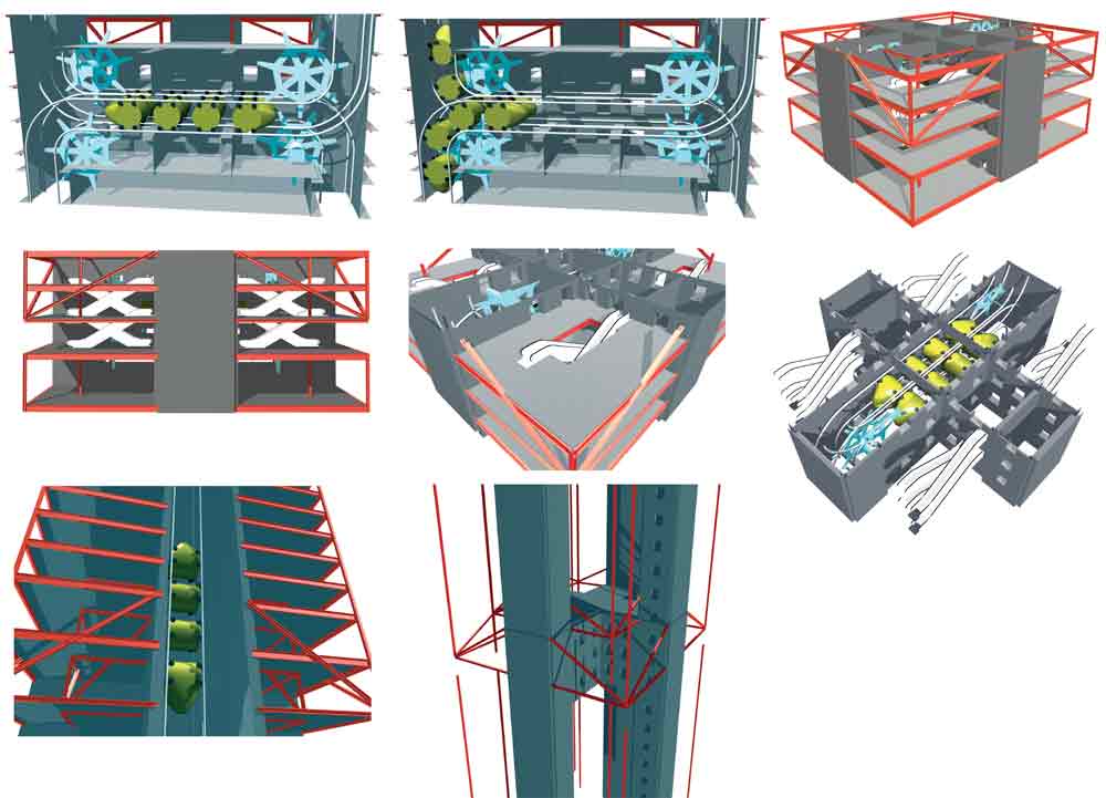
Figure 9: Articulated funiculator train-station renditions 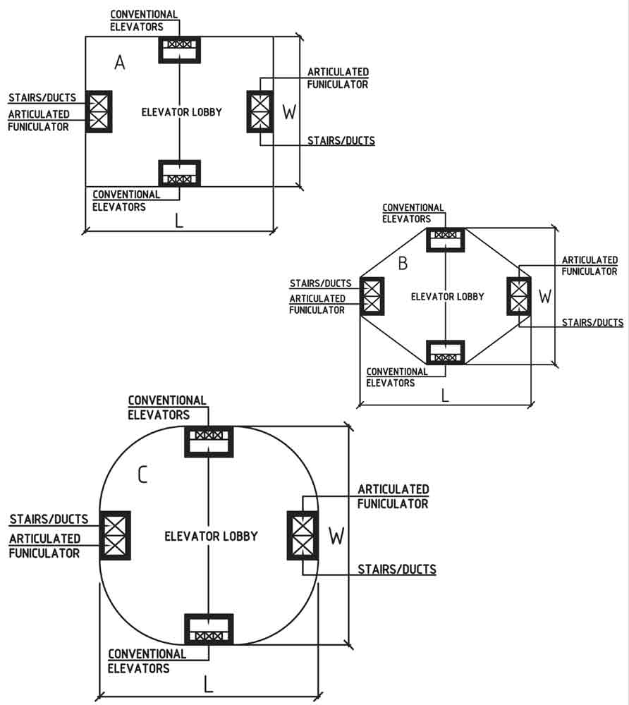
Figure 10: Floor-plate options and usable floor-plate ratios 
Figure 11: Vertical-transportation plan 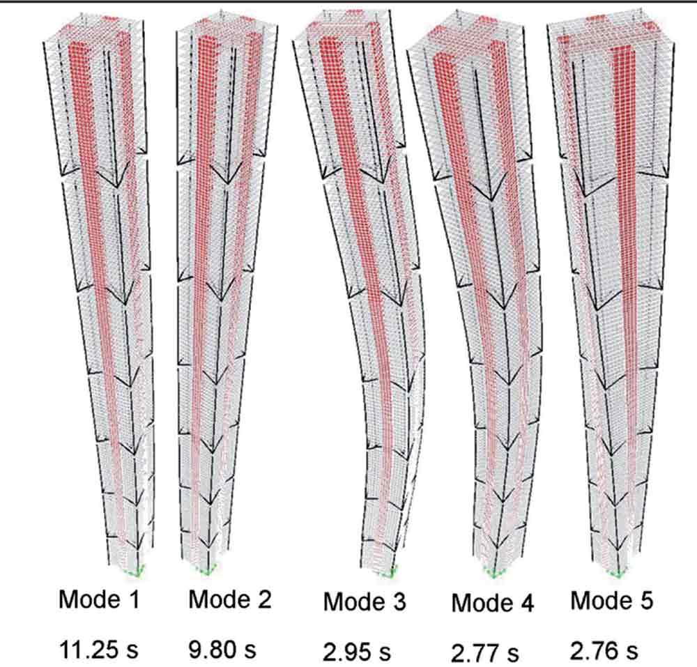
Figure 12: Prototype building modes’ shapes 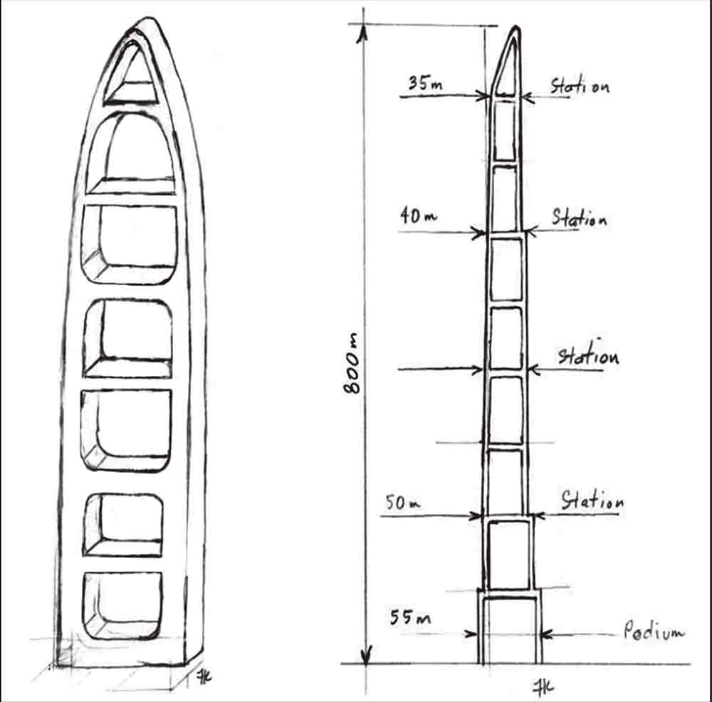
Figure 13: Tubed mega frame options
References
[1] Skyscrapercity, skyscrapercity.com [Accessed April 2012]
[2] Population Reference Bureau, prb.org [Accessed April 2012]
[3] Guardian,www.guardian.co.uk/news/data blog/2009/aug/18/percentage-population-living-cities [Accessed April 2012]
[4] Binder, G. 101 of the World’s Tallest Buildings, Images Publishing, 2006.
[5] Council on Tall Buildings and Urban Habitat (CTBUH), CTBUH Skyscraper Centre.
skyscrapercenter.com [Accessed April 2012]
[6] Sarkisian, M. Jin Mao Tower’s Influence on China’s New Innovative Tall Buildings, CTBUH, 2006.
[7] Xia, J., Poon, D. & Mass, D.C. Case Study: Shanghai Tower. CTBUH Journal, Issue II, 2010, p. 12-18.
Reprinted from Elevatori. Originally presented at the CTBUH 9th World Congress 2012 in Shanghai and first published in the book Asia Ascending – Age of Sustainable Skyscraper City under the title “Articulated funiculator & the tubed mega frame.”
Get more of Elevator World. Sign up for our free e-newsletter.

