We take a look at a few of the primary engineering issues that may complicate a cab refurbishment project beyond simply replacing or changing the internal décor.
by Phil Andrew and Dr. Stefan Kaczmarczyk
This article is based on a chapter that can be found in Systems Engineering of Elevators, available later this spring at website: www. elevatorbooks.com
Introduction
An elevator system is more than a collection and assembly of different components, but is truly a system, in which the interfaces between components are vitally important and the characteristics, both physical and operational of each component or subsystem, must be related (in many cases, intimately) to the characteristics of others. In this respect, the cab is no less an engineering component than any other, and its characteristics (particularly its mass and balance) must be related to the remainder of the elevator system. Our purpose here is to outline a few of the primary engineering issues that may complicate a cab refurbishment project beyond simply replacing or changing the internal décor.
While it is quite true that the actual work of changing the internal décor and finishes of an elevator cab may be accomplished in a day or two, it is essential that adequate time is allocated before the actual refitting work to ensure, through appropriate and fully documented surveying and testing fol -lowed by design calculation, that the changes do not erode the design safety margins of the system. After re fitting is complete and before the elevator reenters service, adequate tests must be carried through to demon strate and document that the integrity of the system has been preserved.
A major issue in refurbishment or modernization of an existing elevator cab is the potential to erode the margin of safety in the original de-sign. Elevator systems are designed, quite deliberately, with large margins of safety (e.g., a minimum factor of safety in the suspension, margin of safety on buckling and bending of the guide rails, etc.). It is very easy for a refurbishment to detract from these margins. While, for example, the addition of mirrors in the elevator cab may appear to be a simple “shop- fitting” exercise, the additional mass might, in a marginal case, reduce the rope and guide-rail factors of safety below acceptable limits. A rope static factor of safety that has been reduced to, say, 11 rather than the original 12 (depending on application) will not be noticeable in normal operation but will mean that the elevator may no longer comply with the original safety standard against which it was specified and designed. Further-more, in some circumstances such as “counterweight jump,” the factor of safety may be momentarily reduced, in practice, to a much lower value. Also note that it may well be that the original system has a design factor of safety on the suspension well in excess of the minimum required for code compliance, since the rope loading is closely related to rope life. If the factor of safety is reduced, even though still in compliance with code, the building owners may find themselves facing more frequent rope replacement costs.
In considering the engineering issues, we must also take into account the “user expectation.” Although to an elevator engineer, the concept “elevator” brings to mind the complete system – elevator machine, ropes, cab, counterweight, buffers, safety gear, governor, etc. – to the lay public, it may well be that the concept is con-fined almost entirely to the visible parts of the elevator, i.e., the interior of the cab, and perhaps the landing and cab doors. Indeed, the concept that the cab doors are successively coupled with a separate set of landing doors at each landing entrance is unlikely to be in the forefront of the normal passenger’s consciousness. In consequence, if an elevator cab is refurbished (particularly if the décor is changed, e.g., by the introduction of mirrors, a significant upgrade of internal finish or even a simple color change), the owner’s legitimate intention may well be that the user’s perception should be that this is a “new” elevator. However, we must take account of the implications of that perception.
Engineering Issues
Perhaps the first point to make is elementary. As implied in the introduction, any modernization, whether partial or complete, must not reduce the level of safety of the elevator below that which existed at the time when the elevator was originally installed or upgraded to compliance with a later code version. In the con-text of a cab refurbishment, this means that, in particular, we must consider the implications of a change to the mass.
A change to the cab décor (e.g., addition or removal of mirrors in the car) may change the car-side fixed mass P. However, other changes (e.g., replacement of doors, door operator, etc.) may also result in a change of suspended mass and affect the fore and aft balance of the car. It is a matter of engineering judgment in any particular case whether a change of mass is significant. Standards indicate that a change of 5% or more would be regarded as significant. Nev er the -less, it is possible that a smaller change might require careful consideration.
In order to ensure that the integrity of the system is maintained, it is important that the relevant mass before and after the change is established, in order for the consequences for the overall system to be determined. This means also establishing the mass of any components (e.g., décor panels) to be removed. A change in suspended mass makes it mandatory that a full design calculation is undertaken.
Any increase in the car-side fixed mass must clearly be reflected in a re-balancing of the counterweight that is at least sufficient to guarantee traction. We may assume that at the point where the applied traction ratio is a maximum, the hoistway masses are made up of a number of components (Table 1).
For the purpose of this particular discussion, we have lumped the transfer mass of suspension, compensation and traveling cables with the car and counterweight fixed masses to generate maximum car-side and counterweight-
side masses Pmax and Mcwt. Clearly, Pmax will be greater than the simple mass of the cab itself.
The worst-case traction ratio will usually occur either with an empty cab near the uppermost floor or a full cab near the lowest floor. Before modification, during emergency braking with rated load traveling downward, with braking deceleration ab, the applied traction ratio will be

While braking into the highest floor with no load in the car, the braking deceleration will be abP and

If we assume now that the car-side mass is changed by an amount δ P, then if the brake setting is left unaltered, the braking deceleration would change due to the change in mass. However, we will assume that the brake setting is
adjusted to provide the same braking deceleration ab or, alternatively, that δ P is small in comparison with the total hoistway mass. If the worst-case traction ratio before modification occurs with rated load in the cab approaching the lowest floor and is not to change, we must change the counterweight mass by an amount δMcwt, such that

or, if the worst-case traction ratio is when an empty cab is approaching the highest floor:


It is important to note at this stage that if the counterweight is adjusted in accordance with equation 3 or 5, while the worst-case traction ratio will not change, the adjustment will change the balance, since the proportion of counterweight mass associated with balancing the load will be changed. On the other hand, if the obvious solution is taken (i.e., the counterweight mass is simply adjusted by an amount δ P, the same as the change in car mass, the traction ratio will be altered, but the balance will not.
We must also note that if the counterweight mass is altered in accordance with equation 3, then it is not inconceivable that emergency braking in the down direction would cease to be the worst-case condition for traction, and vice-versa if δMcwt is calculated in accordance with equation 5. Our purpose here is not to devise a methodology for recalculating the counterweight, but rather to investigate the potential problems associated with a change to the car-side fixed mass.
The simplest approach is to make δMcwt equal to δ P, in which case neither equation 3 nor 5 is satisfied; i.e., we now have

where acceleration a relates to the condition giving rise to the worst-case traction ratio.
Up to this point, we have not declared whether the change δ P in the car-side fixed mass is to be an increase or a decrease. If we increase the fixed mass, then δ P is, algebraically, a positive number, while for a decrease, δ P will be negative. Consequently, for an increase in fixed mass, provided that

then the traction ratio will be reduced from its value prior to modification; i.e., the margin between the applied and the critical traction ratios will improve, while for a decrease in fixed mass, the margin will only improve provided

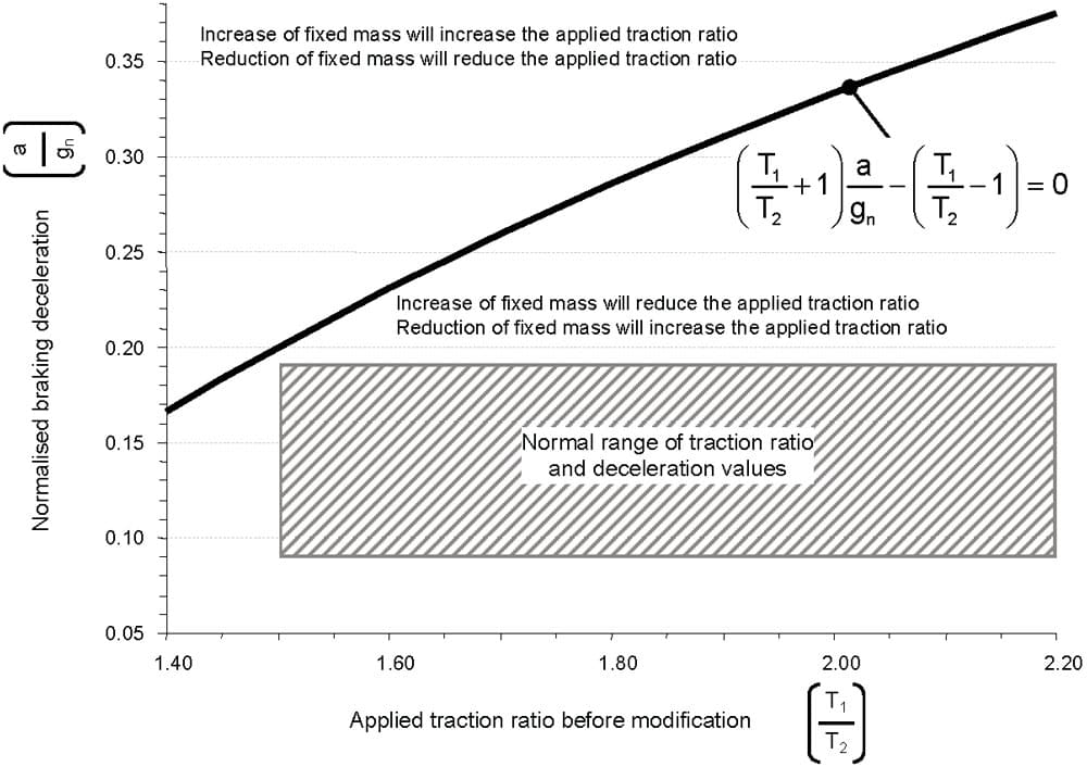
The boundary condition is found by calculating values for

as shown in Figure 1.

t is clear that for all practical applications, we would expect the deceleration (whether braking or normal deceleration) to fall within the range 0.09gn ≤ a ≤ 0.19gn and a traction ratio to fall within the range 1.5-2.2, as shown by the shaded area in Figure 1. In this region, an equal increase in mass on car and counterweight sides will actually reduce (i.e., improve) the applied traction ratio, while a reduction in mass will increase it. We should emphasize at this point that we are concerned here with the applied traction ratio (i.e., the actual traction ratio that will occur in practice) and not the critical traction ratio, which is a matter of the geometry of the traction machine and rope centers.
However, although we can be confident that an in-crease in cab mass is unlikely to cause deterioration in the traction ratio (which must, nevertheless, be checked), there is a number of other issues that may be adversely affected by a change in mass. Importantly, the resonant frequencies of the suspension system will change with any modifications of the masses – be it an increase or a decrease.
Increase of Car-Side Fixed Mass
As noted earlier, if the cab mass is not increased by more than 5%, most safety codes will not demand that the system is revised in total. However, it is important to bear in mind that such a relaxation applies to the mass of
the cab only, not to Pmax, which we have used here. Furthermore, to avoid creeping erosion of safety margins, it is important that any change of mass is assessed against the original cab mass, or the cab mass as established at the last refurbishment that included a full calculation of the system. Over the lengthy service life of an elevator, it is possible that the cab may be remodeled a number of times. Two or three successive remodeling projects, each of which remain within 5% of then-existing cab mass, might well creep the cab mass beyond the permitted 5%variation. Other issues are listed below, but the list is not exhaustive:
- The strength of the civil structure must be capable of supporting any increased mass, bearing in mind that the increased mass is applied to both car and counter-weight sides.
- The loading on the sheave shaft and diverter/secondary pulley is increased by any total increase in mass.
- The machine supports (piers or steels) must be adequate for the increase in total loading.
- The factor of safety of the suspension must remain within permitted limits (which, for rope life considerations, may be considerably in excess of the minimum permitted by code).
- Guide calculations will have to be rechecked to ensure that guide deflections and buckling loads will not be excessive. With regard to the latter, any change which moves the center of mass, even if the total mass is unchanged, will also require checking, since the bending loads on the guide rails will change.
- The buffers and safety equipment in the pit must be adequate for the altered mass. This may mean tests and measurements to establish their capabilities.
- The rating of the safety gear and any protection against over speed in the up direction must be adequate for the revised loading.
As an example of the issues involved, if a progressive (Type B) safety gear is employed, whether the mass has been increased or decreased, there is clearly an issue with regard to the deceleration values to be expected.
If the relevant safety code specifies the performance in terms of rated speed, governor tripping speed and maximum/minimum stopping distance with rated load and an intact suspension, then having established that the modified system still falls within the rating of the safety gear, this is comparatively simple to verify by an appropriate full load test.
However, where performance is specified in terms of arrest in free fall with rated load, the issue is somewhat more problematic. It is to be emphasized that where code requirements are specified in terms of free-fall performance, there is no currently recognized or accepted method for confirming free-fall performance by testing a safety gear in situ with an intact suspension. The issue is the subject of discussion amongst experts, the question being whether a test which ensures that the suspension becomes slack during the test can be used to estimate the free-fall deceleration with rated load. In the European context, EN 81-1: Annex D specifies a commissioning test with 125% rated load and traveling at rated speed or lower. This test does not nor is intended to check the free-fall performance of the safety gear. It is simply a test to ensure that the safety gear has been installed correctly and is functional. It is the type examination and free-fall test, and the consequent certification of the unit that has established the safety-gear performance. Consequently, after a modification, it is not sufficient simply to perform the confirmatory test specified in Annex D.
Reduction of Fixed Mass
A reduction in car-side fixed mass is, in principle at least, easier to deal with from the systems viewpoint. We have seen from Figure 1 that a reduction in fixed mass will cause an increase (i.e., a deterioration) in the applied traction ratio. Also, the action of the safety gear may then be too harsh for code compliance. The simple solution is to ensure that the cab is ballasted up to its original mass, so that the operating conditions are nominally unchanged. This may involve an alteration to the car frame in order to introduce the additional ballast mass. However, that may not be the whole story.
Balance of the Cab
A more subtle effect of a cab remodeling project is its potential to affect the fore and aft balance of the cab. Because a new décor may change the weight distribution within the cab, this is an issue which may well arise independent of whether the mass of the cab is changed, although a change of mass (either increase or decrease) is, of course, likely to change the balance. If there is an initial reduction in mass, then the addition of ballast weights to restore the overall cab mass is likely to change the balance, while an increase in mass, of itself, is almost certain to do so.
The important aspect of a change in balance is the potential effect on the guidance system. In an ideal system, the cab will hang from the suspension, imposing no lateral loading on the guide shoes other than that required to overcome any residual torsion from the suspension members, or due to uneven loading in the cab (e.g., a partial load of passengers all standing at the front or rear of the car). Indeed, in a high quality installation, with a tight ride quality specification, the original installer will have gone to considerable lengths to balance the cab correctly fore and aft in order to ensure a minimal feed-back of any slight imperfections in the guide rails and guide joints into the cab.
Any inadvertent change of balance may lead to a deterioration of ride quality or (even if this is not so) overloading of roller guide shoes or increased wear of sliding shoes. It does the commercial interests of the company carrying out the remodeling no favors if, subsequent to the provision of a much improved décor in the car, the owner is then subjected to increased complaints regarding quality of ride or increased costs due to more frequent replacement of guide shoes (along with the potential for increased frequency of rope replacement as discussed earlier).
From the viewpoint of safety, an alteration on the car balance will also change the bending loads on the guides during safety-gear operation. Whether or not a modified balance is to be allowed to remain, the guide calculations must be checked in order to ensure that the margin of safety for the guide material is not eroded beyond the permitted limits of bending and buckling stress.
Perception of the Changes
We must also consider the perception of users and potential users over and above the foregoing engineering issues. Quite properly, as hazards and risks become apparent, over time, both the safety code and good design practice will change to reduce risk and/or eliminate hazards. It is often said that the safety code (in whichever territory) is a “minimum” standard, and good design will provide performance that goes beyond the requirement. Thus, leveling accuracy has improved over time independent of the detailed requirement of the safety code. Further, in terms of emergency stopping, while codes demand that the electromechanical brake (and, ultimately, the governor/safety-gear combination) are employed to bring the elevator safely to rest in the event of overspeed, many control systems will detect an incipient overspeed before the elevator reaches the governor tripping speed (electrical or mechanical) and bring the elevator to rest, or even reduce the speed to a low level and proceed to the nearest landing level to release passengers. In the past, such facilities were limited to more sophisticated installations, but as the technology has become more cost competitive, more and more installations provide this kind of performance so that today, even an elevator in a parking garage may well provide “VV performance” in terms of leveling, etc.
The service life of an elevator is long in comparison to many products – somewhat longer than, say, the average automobile. Consequently, when it comes to refurbishment or modernization, the elevator to be refurbished, although code compliant, may have a performance well short of what has come to be expected. As an example, a low-speed residential elevator may still employ a single- or two-speed AC control, with variable leveling accuracy and slowdown performance depending on the load in the car.
If such an elevator is refurbished (particularly if the cab or its décor is replaced), then to the passenger, it becomes a “new” elevator and raises an expectation that the performance will have been brought up to modern standards. In such circumstances, a leveling accuracy of ±20 mm or±30 mm (which was quite acceptable prior to refurbishment) may suddenly constitute a more significant tripping hazard simply because prior to refurbishment users expected no better. After refurbishment, passengers will not expect to step up or down from elevator sill to landing. Indeed, it is not entirely beyond the bounds of possibility that a tripping, which because of the known and accepted standard of performance prior to refurbishment would be allowed to pass, might, after the elevator has been “renewed,” lead to a possible compensation claim.
These issues mean that there are three main aspects to be considered in any modernization or refurbishment, even if the project involves only the cab:
- How is it to be ensured that the proposed modernization/ refurbishment activities will not reduce the level of safety below that originally provided?
- What is required in order to bring the elevator into line with current safety codes, and what are the limitations on such an upgrade?
- What additional risks not explicitly covered by safety codes are involved in the use of the elevator?
It is also worthwhile to consider whether any “partial” refurbishment can, successfully and cost effectively, bring the elevator up to an acceptable standard in the modern context.
Risk Assessment
Overall, the implications of any modification to an existing elevator are wide ranging and potentially hazardous both to passengers and to the maintenance crew. It is important to establish, as far as possible, the parameters of the existing elevator prior to modification or refurbishment (e.g., cab mass, balance, motor power and suspension details). Ideally, the necessary information will be recorded in the technical information kept with the elevator. However, it may be necessary to make suit-able measurements in order to establish the important characteristics of the elevator prior to modification. What is unlikely to be available, as mentioned earlier, is any documentation of the masses of décor panels, etc. proposed to remove. Sufficient information must be established to allow the implications of any proposed modification to be explored fully, so that the wider effects of the modification can be accounted for.
In considering a modification (however “minor”), a comprehensive and documented risk assessment (ISO/TS 14798: 2009) and safety audit of the current installation, both in its current condition, and, equally important, in the condition as originally installed, is indispensable. Such an audit is the precursor to a further assessment of the proposed modification/refurbishment.
Whether the proposal is for total replacement, or replacement or refurbishment of individual components of the system, risk assessment is fundamental to a successful project and must account not only for the direct consequences of the proposal, but also for the peripheral issues. Thus, if, for example, it is proposed to replace landing or car doors and a direct like-for-like replacement is not intended (e.g., a replacement with different material or doors with a decorative skin), then not only are the functional issues (kinetic energy, closing force, etc.) important, but also is the effect on the perception of users as discussed above.
While these issues are fairly obvious, the objective of a full risk assessment is to tease out the more subtle (and, in consequence, potentially more hazardous) issues that need to be taken into account.
Conclusion
In this article, we have considered some of the issues underlying cab modification and refurbishment projects, particularly in relation to changes in the mass. This discussion is not intended as a design manual for refurbishment projects, but simply to draw attention to underlying issues that may arise and might potentially go unnoticed.
Clearly, with elevators’ longevity, designers will come across refurbishment projects of them dating back to very early versions of safety codes in which components such as picket gates (prohibited by modern codes) were permissible.
Nevertheless, whatever the age of the elevator, it is important that any refurbishment or remodeling work does not erode the margins of safety originally incorporated into the design. With the normal safety factors built into
Get more of Elevator World. Sign up for our free e-newsletter.


