Compact Guide-Rail System on Inclined Elevator in Spain
Jun 1, 2011

ThyssenKrupp Elevator provided the guide-rail-system equipment for this unique mountainside installation in Bilbao, Spain.
Bilbao in north Spain is the provincial capital of Vizcaya. With 354,860 inhabitants, it is among the most populated cities in the Basque Country Autonomous Community. As a port city on the coast of Cantabria, it was an important commercial center in the 14th century. It was heavily industrialized in the 20th century and became an epicenter of industrialization in Spain. Its civil architecture is leading the way for additional aesthetic, social and economic revitalization. The city center is surrounded by two 400-meter-high mountain ranges.
Installing an inclined elevator on the Camino de Zurbarán was initially conceived to solve the problems of access between the road, which is halfway up the hillside, and the top of a rocky folded outcrop. This area is generally residential with a high population density and some small businesses.
Although the initial objective was not to provide a means of transportation for a large number of people, use of the inclined elevator averaged 510 trips per day during its first month of service. Estimates indicate that more than three million people will have used this elevator during its first year of service, which is approaching this month. The elevator was well integrated with its surroundings and rep-resents a moving advertisement. The elevator has reduced energy consumption and is visible from many different parts of the city.
Elevator
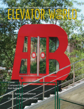
The car is a panoramic type in the shape of a “B” for Bilbao. It is equipped with three boarding places. It features safety glass and interior finishing in stainless steel, and the exterior is red plate. The car is equipped with a control panel for persons with disabilities, an indica-tor panel, a fold-down false roof and a security camera.
Installation Specifications
- Load: 1875 kg (25 persons) u Speed: 1 mps
- Distance: 63,954 m
- Slope: 27.22 m
- Inclination: 25.19°, constant and in a straight line
- Journey time: 75 sec.
- Number of stops: three u Traction control: control by variable frequency and tension drive variator for gentle starting and stopping
- Location of engine room: upper
- part of the elevator next to the upper boarding area
- Doors: Both the car and landing doors have automatic central openings made of two glass plates with regulated speed operators and mechanisms at the bottom, both measuring 900 mm X 2,000 mm. There are no mechanical elements between the doors, which means that the distance between the platforms is smaller. The landing doors have an LCD signaling system at their tops, with the control panel installed in their frames.
Guide System
The elevator is equipped with a compact guide system based on HEA commercial profiles, which sup-port and transmit the forces deriving from the weight of the vehicle, the counterweight and the users to the anchoring plates. The vehicle moves using the upper wing over a stainless-steel plate and the counterweight in the interior of the pro-files, with a 1,200-mm gap between the guiderails. A T-18c (ISO T125/B) guiderail assembled on crossbeams anchored to the profiles is used to wedge and guide the vehicle.
Rollers on this guiding system are important in this type of elevator because the majority of the vehicle weight (sling and car) and the rated load (more if the inclination angle is lower to the horizontal plane), is sup-ported by the rollers and transmitted to the profiles, while in a vertical elevator it goes to the traction ropes. In this elevator concept there are types of rollers with different functions (vehicle moving, guiding and anti-capsizing), three different in the sling and two different types in the counterweight. All consist of a poly-urethane band on a steel core, and are resistant to harsh weather conditions and with a smooth rolling.
Both the sling and counterweight rollers, which support these components loads, have been mounted on a swinging system in order to distribute loads equally on each roller, and, thus get a balanced wear.
Sling
The sling has a standard design adapted to the incline of the installation. It consists of space for inspection workers and houses the safety systems like the speed limiter, remote alarm device and opera-tor controls, load-weighing device and shaft-copying system. Access is provided through a trap door that is aesthetically integrated into the car. The maintenance operator sits on a pilot seat, and the maneuvers are controlled using an inspection panel. In addition, there is a rolling system with four large diameter polyurethane two-wheeled trains for heavy loads and long journeys, and another anti-capsizing safety wheel in each train. Another two four-wheel trains guide the vehicle taking as a reference the wedging guide in order to avoid lateral displacements. Counterweight
With a low-profile design to allow it to move inside the HEA profiles, robustness and a high filling capacity, the counterweight moves using four two-wheeled trains, with an additional wheel on each train to avoid possible lateral displacement. The rollers in this case are smaller than the ones in the sling, allowing them to roll on the inner profile wings. Due to this, a counterweight with a com-pact design in respect to the rest of elements in the transportation system can be obtained.
Traction Set
The set consists of a new design for inclined traction in an engine room beneath the upper loading place, and it consists of a robust structure of beams and set of buffers arranged on three axes which allow, at the same time, the appropriate fixing of the machine and the softening of all dynamic forces received by the machine and structure.
Compensation Set
A compensation set was included to increase the traction of the traction pulley in order to comply with standards. It consists of a guided counterweight and righting pulley for the tensing of the compensation cables.
Doors
There is a system of motorized doors in both the car and landings using regulated speed operators with the mechanisms at the bottom. The system, the patent for which is still pending, consists of a communication system using infrared lights be-tween the car door which acts as the master door and the landing doors which act as slave doors. The main advantage of this system is that there are no mechanical elements between the doors, meaning the distance be-tween the platforms is smaller. Safety Systems
It is equipped with a limiter standardized for vertical elevators, assembled on a sliding tray within the apron, together with two righting pulleys. By a single pull on the cable when the speed exceeds the pre-established limit, the limiter becomes blocked, the tray slides along its guiderails, and the vehicle continues to advance. A small lever is activated, and, in turn, acts on the progressive jamming mechanism, which also slides over low-friction guiderails, compressing the cork buffer, which slows the movement still further and doesn’t lose braking reliability. When unjammed, a recovery spring takes the tray and the jamming buffer back to their original positions.
There is also a tensor that keeps the limiter cable tense in the direction of the trajectory using a small vertical counterweight and righting pulleys, a safety brake integrated into the machine axis (which prevents the elevator from rising too quickly) an emergency-stop system and a lifeline for assembly and maintenance. Electrical Wiring
The power, signaling/communication and video cables are flexible cables laid between the maneuver cupboard and the car by means of a cable-carrying chain (like in automatic warehouses) for an inclined sliding application, which moves silently along a stainless-steel channel. The shaft cables are in a tube and prepared for outdoor conditions in a marine environment.
Rescue
There is an evacuation stairway in case passengers become trapped in the elevator. It runs parallel to the entire route of the elevator. Access is via the car door and a system using a platform and handrails to cover the different heights of the two elements at certain points along the way.
From its first day of service, the elevator has become a means of trans-port for many. In one month, the elevator became a habitual means of transport for people, although that was not its original intended use. It is hoped that with time, it will become more of an attraction, joining other significant works in the city.
Get more of Elevator World. Sign up for our free e-newsletter.