Coordinated Control of Dual PWM Converter for Elevator Drives
Jul 1, 2012
Theoretical analyses and experimental results of dual PWM converters are examined.
by Han Shuang, Zheng Jiong, Luo Zhiqun and Wan Jianru
Dual pulse-width modulation (PWM) AC drives are one of the most energy-efficient elevator technologies. Here, we will focus on the coordinated control of dual PWM converters integrating elevator drives with energy feedback. Theoretical analyses and experimental results show that the presented system with simple circuit structure can realize the following: four running motor quadrants, bidirectional energy flow, low total harmonic distortion (THD) and high power factor on the line side. In all, the system can save energy for the elevator and reduce power pollution caused by converters on the grid side.
As elevators account for approximately 20% of the total energy consumption of modern high-rise buildings, more and more attention is being paid to energy-saving elevator technologies. The energy-saving method adopted by most manufacturers is the gearless permanent-magnetic synchronous motor (PMSM), which has a certain energy-saving effect, yet still wastes regenerative energy. An energy-feedback device is added to the traditional AC/DC/AC drive system in some elevators. The energy savings might seem obvious, but the reliability of the system is poor, and the feedback power interferes with the grid and other electrical equipment. By using dual PWM converters, the regenerative braking energy can be fed back into the grid. Also, the power pollution on the grid side caused by elevator converters can be decreased, namely realizing low THD in input current and a high power factor.
Dual PWM Converters for Elevator Drives
Uncontrolled diode rectifying circuits are extensively used in elevator converters. Though the circuit structure is simple, regenerative braking energy of the motor is wasted by the braking resistance instead of being fed back into the grid. Other disadvantages of diode rectifiers include high-input current harmonics and low power factor, both of which pollute grid power.
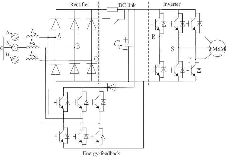
The traditional braking mode wastes energy and limits braking performance. As a result, some enterprises and research institutions have proposed adding an energy-feedback device to the traditional rectifier (Figure 1). This device adopts active inversion techniques, which invert the regenerative energy to AC power in the same frequency and phase as the grid, and returns it to the grid. Thereby, bidirectional energy flow between the DC link and source is possible, and the regenerative braking energy can be recycled. However, the feedback power interferes with the grid and other electrical equipment. Also, the energy-feedback system increases cost, enlarges the volume of the device and decreases reliability and dynamic response speed.
A dual PWM converter (Figure 2) is composed of line-side filter inductance, a three-phase PWM rectifier consisting of insulated gate bipolar translator (IGBT) and anti-parallel diodes, DC link filter capacitance, three-phase PWM inverter consisting of an IGBT and an anti-parallel diode. Elevators using dual PWM converters greatly improve AC power quality, due to the advantages of constant DC-link voltage, low harmonic input current, high power factor and bidirectional power flow. So, it is possible to realize feedback of regenerative braking energy into the grid, ultimately saving energy. In addition, the motor can run in four quadrants, which is important to the elevator.
Operating Principle and Control Strategy
Operating Principle
When the motor of the elevator is running, the line-side filter inductances and three-phase PWM rectifier work together as a boost-type rectifier, with a DC voltage output equal to peak voltage of an AC source or higher. The energy flows from the line side to the DC link by controlling the switch state of the IGBT.
The DC-side filter capacitance, as the connection between the rectifier and the inverter, is the load of the rectifier and source of the inverter. Filtering characteristics of the capacitance can smoothen the waveform and decrease DC voltage ripples. The inverter transforms the DC voltage into a PWM modulation wave equivalent to the sinusoidal voltage of the elevator motor. The forward and reverse rotation of the motor can be adjusted by controlling the order of phase sequence of the inverter.
When the elevator is in a light-loading up, heavy-loading down or braking state, it generates renewable power due to the inertia effect of the load. Conversely, the PWM rectifier serves as an inverter, and the inverter serves as a rectifier. Therefore, the energy can flow from the elevator-motor side to the grid side, reverting the feedback of the regenerative energy into the grid.
Coordinated Control of Dual PWM Converters
The traditional dual PWM converter, which has an inverter and rectifier with its own control circuit, controlled separately, leads to increased volume of the device and additional hardware and software resources for the communications control system for the controllers. Keeping the power flow of the rectifier side equal to the inverter side enables the energy difference between the rectifier and inverter per unit time to decrease. This then decreases the voltage fluctuation and capacitance of the DC link.
With dual PWM converters with motors, the regenerative energy is gathered in the DC side capacitance, leading to an increase in DC link voltage, affecting the safe operation of the system. The load power feed-forward method can restrain the voltage fluctuation of DC link. The direct-power control strategy is used for PWM rectifiers. The abrupt change of the motor state is fed forward, directly changing the reference value of the inner power loop of the rectifier. The regulating pressure of the DC voltage loop is relieved, so the DC-side voltage can be kept constant with a smaller capacitance.
Note that the feed-forward load power instruction is calculated according to the voltage and current instruction; thus, controller delay caused by direct detection is decreased. Rotor field-oriented vector control is adopted for a PMSM. Figure 3 shows the control-principle diagram of the software circuit.
Figure 4 shows the block diagram of the digital signal processor (DSP) software control. The system is controlled by dual DSP. The line-side rectifier is controlled with the direct-power control strategy by DSP1. In the analog-to-digital converter of DSP interrupt routine of DSP1, the load power is added to the active-power instruction signal as a feed-forward input. The inverter and PMSM are controlled with the vector-control method by DSP2. DSP2 also calculates the load-power instruction according to voltage and current instruction and delivers it to DSP1. The dual DSP communicate with each other through chip IDT70V261LPF, which has two address and two data buses connected to the DSP peripheral address and data buses, respectively. The dual DSP exchange data by setting the external interface register (XINTF), which enables DSP to access external space periodically.
Experiment
An experimental hardware system according to the circuit shown in Figure 2 was constructed, primarily including the main circuit of the rectifier side, DC and inverter sides, PMSM and dual DSP control board (Figure 5). Note that the DSP is TMS320F2812 of Texas Instruments Co.
Result Analyses
The experimental parameters were set as follows: input at 25 V, inductance at 4 mH, DC-link capacitance at 660 µF and instruction value of 60 V. The rated power of the PMSM was 0.55 kW, rated current was 1.5 A, rated speed was 1,500 rpm, number of pole pairs was two and the flux of the permanent magnet was 0.66 Wb. The experimental waveforms are shown in Figures 6 and 7. Note that the waveforms are output by DSP digital-to-analog converter of DSP.
Figure 6 shows the waveforms of phase voltage and current of grid side at the motor-operation running state. It also illustrates the dual PWM converter realizing high power-factor rectification at the grid side. Figure 7 shows the waveforms of the phase voltage and current of the grid side at the state of simulating regenerative energy by using back-emf load. It can be seen that the phase voltage and current of the grid side are nearly contrary, which means the PWM rectifier is parallel in the grid with a high power factor and realizes bidirectional energy flow.
Conclusion
Simulation analyses and experimental results show that the presented system can save hardware and software resources, and solve the management problem of regenerative energy. The regenerative energy can be fed back into the grid when the motor is in its regenerative braking state, thus saving energy for the elevator. In addition, the system can decrease the power pollution of the grid side caused by elevator converters, namely realizing low THD of input current and high power factor.

Figure 2: Configuration of a dual PWM converter 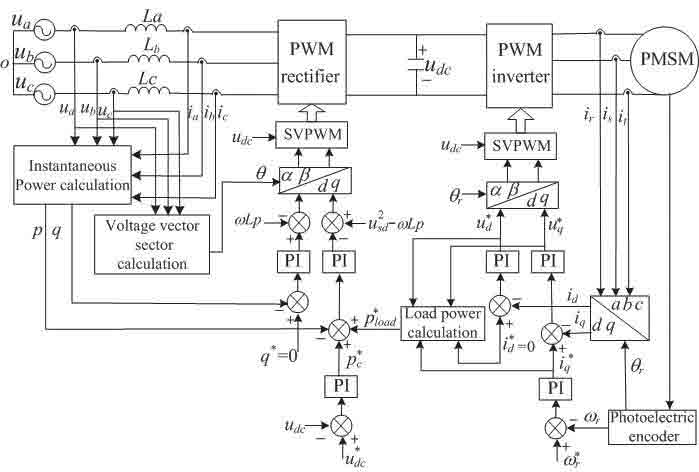
Figure 3: The control-principle diagram of the software circuit 
Figure 4: Block diagram of DSP software control 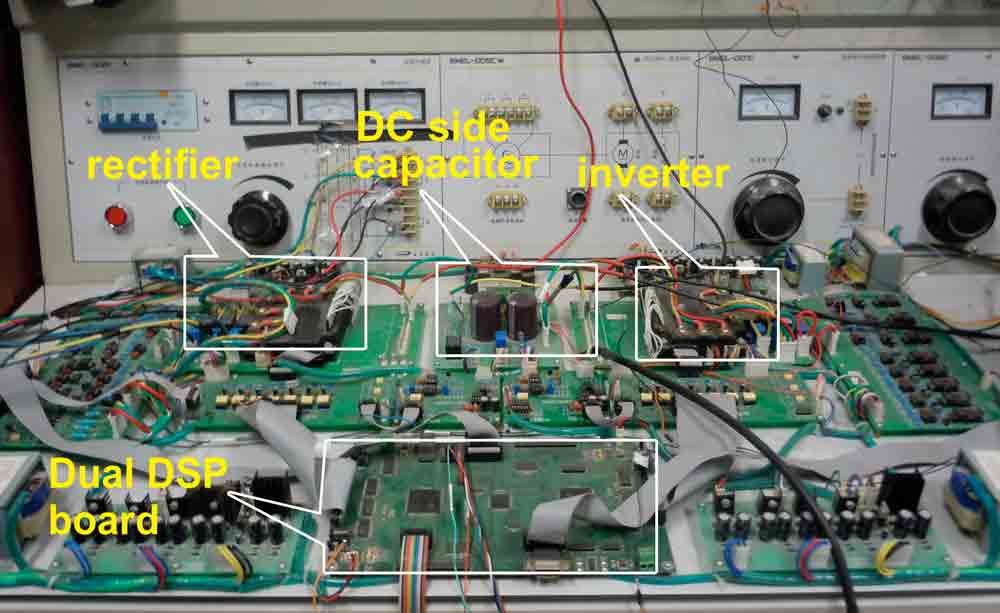
Figure 5: Experimental dual PWM converter device for elevator 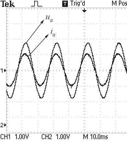
Figure 6: Phase voltage and current of grid side at the motor-operation running state 
Figure 7: Phase voltage and current of the grid side at the energy-feedback state
References
[1] D.W. Chung, H.M. Ryu, Y.M. Lee, S.K. Sul, S.J. Kang, J.H. Song, J.S. Yoon, K.H. Lee and J.H. Seo, “A New Configuration of Drive System for High-Speed Gearless Elevator,” in Conf. Rec. IEEE IAS Annual. Meeting, 1999, pp. 307-310.
[2] Wang Jiuhe, Yin Hongren and Zhang Jinlong, “Three-Phase Voltage Type PWM Rectifiers with Inner Power Loop and Uuter Voltage Square Loop.” Journal of University of Science and Technology Beijing, Vol. 30, No. 1, 2008, pp. 90-95.
[3] Tokuo Ohnishi, “Three-Phase PWM Converter/Inverter by Means of Instantaneous Active and Reactive Power Control,” Proc. IEEE IE-CON’1991, pp. 819-824.
[4] M. Malinowski, M.P. Kazmierkowski and A.M. Trzynadlowski, “A Comparative Study of Control Techniques for PWM Rectifier in AC Adjustable Speed Drives,” IEEE Trans. Power Electron., Vol. 18, No. 6, 2003, pp. 1390-1396.
[5] Namho, H., Jinhwan, J., Kwanghee, N. “A Fast Dynamic DC-link Power-Balancing Scheme for a PWM Converter-Inverter System,” IEEE Trans Ind Electron, 2001, pp.794-803.
[6] Li Mingshui, Wan Jianru, Li Guangye and Li Bin, Research On Power Feed-Forward Control Strategy of PWM Rectifier. 4th International Conference on Power Electronics Systems and Appli-cations, 2011, pp.1-6.
Get more of Elevator World. Sign up for our free e-newsletter.


