
The ins and outs of mixed-signal equipment

Value: 1 contact hour (0.1 CEU)
This article is approved for Continuing Education by NAEC for CET® and CAT®.
EW Continuing Education is currently approved in the following states: AL, AR CO, FL, GA, IL, IN, KY, MD, MO, MS, MT, NJ, OK, PA, UT, VA, VT, WA, WI and WV | Canadian Province of BC & ON. Please check for specific course verification of approval at Elevator Books.
Learning Objectives
After reading this article, you should have learned about:
- Mixed-signal systems
- Pixelation
- Analog and digital domains
- MOSFETs
- Two types of MOSFET used in CMOS configuration
Analog and digital signals are strikingly different and require different tools, techniques and bodies of knowledge to work with them. Some say analog signals are easier to understand, while others are more comfortable in the digital domain. When it comes to mixed-signal equipment, such as an elevator motion controller-variable-frequency drive (VFD), expertise in both is essential.
An elevator is actually a mixed-signal system. What this means is that it operates using both digital and analog signals. Small, relatively simple devices, usually embedded in integrated circuits (ICs), convert an analog signal to a digital signal. They are known as analog to digital converters (ADCs). Digital to analog converters (DACs) perform the reverse process. They also are normally embedded in ICs. These conversions occur very rapidly with no loss of information, as we shall see, provided certain conditions are met. We’ll discuss these constraints and how they are met after defining analog and digital signals and describing their functions in elevator systems.
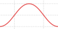
This is an example of an analog signal. Most people recognize it as the sinewave of electrical voltage as supplied to residential, commercial and industrial facilities throughout the world. It is not really the way an AC waveform looks. Rather, it is a graph of the amplitude of the AC waveform plotted against time in Cartesian coordinates. An actual waveform, for example that of sound, consists of periodic variations of air density moving at around 700 mph. These changes in air density impact mechanisms in our ears. They are analog waveforms that are changed to digital signals for processing in the brain. Similarly, electrical analog signals can be drawn in Cartesian coordinates and they have a similar appearance to sound waves, although the changes that are being mapped are electrical.
The defining characteristic of analog waveforms is that they are continuous, with smooth transitions, unless the original signal happens to jump abruptly. In fact, analog waveforms conform precisely to the original signals. That is why they are called analog — they are analogous.
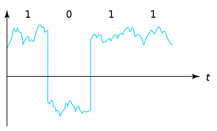
This is the waveform of a digital signal. Notice that it has very fast rise and fall (decay) times. Between these nearly instantaneous transitions are relatively flat high and low levels, in this instance distorted by the presence of noise. If the amplitude of the noise is not sufficient to prevent the receiver from distinguishing high and low logic levels, in conjunction with the transmitter it will reconstruct this and other pulses so that they are once again ideal waveforms. Accordingly, they can be propagated through any number of successive transmitters and receivers without loss of information, all this despite new noise that may be added downstream, provided it is not overpowering. That is a decisive advantage for digital transmission. In analog, the noise is cumulative, whereas in digital it is removed between stages.
Have you watched a satellite dish TV broadcast during a severe rain or snowstorm? The picture is perfectly clear, i.e., the automatic gain control can keep up with the weakening signal, until at a certain point the picture breaks up, freezes, fractures and looks very strange. This is known as pixelation, and it is a consequence of the digital stage no longer being able to distinguish between logic high and logic low levels in the digital pulse train.
There is an ever-evolving number of digital logic families, with different logic high and logic low levels and different threshold levels at which they are distinguished:
- Diode logic
- Resistor-transistor logic
- Transistor-transistor logic
- Emitter-coupled logic
- Integrated injection logic
There are many others. When the name of a logic family is hyphenated, as in resistor-transistor logic, the first device is applicable to the input, and the second device is applicable to the output.
Characteristics of digital ICs include a high-level input voltage, which is recognized by the gate as logic high (1); a low-level input voltage, which is recognized by the gate as logic low (0); a high-level output voltage, which is the minimum voltage available at the output corresponding to logic high (1); and a maximum voltage level available at the output corresponding to logic low (0).
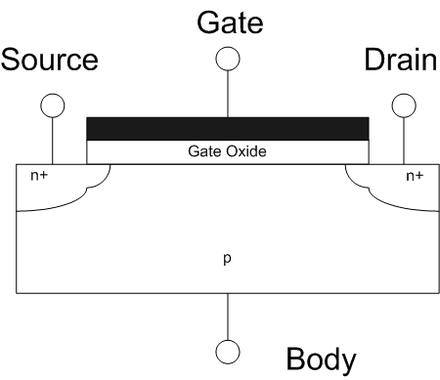
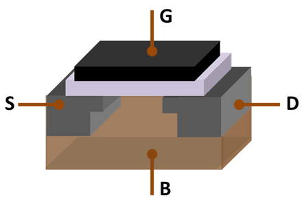
The Field-Effect Transistor (FET), successor to the point-contact transistor and ancestor to its subvariant, the Metal-Oxide Semiconducting Field-Effect Transistor (MOSFET) consists of an active channel through which charge carriers, electrons or holes flow from the source to the drain. Size, shape and conductivity are modulated (analog application) or switched (digital application) by means of the voltage applied to the gate and source terminals. The three FET terminals are:
- Source (S), through which the carriers enter the channel. Current entering the channel at the Source is designated IS.
- Drain (D), through which charge carriers leave the channel. Current leaving the channel at the Drain is designated ID. Drain-to-Source voltage is VDS.
- Gate (G) is the terminal that modulates (analog) or switches (digital) IS or ID.
Source, Drain and Gate in the FET are analogous to Emitter, Collector and Base in the conventional transistor and Cathode, Grid and Plate (Anode) in the Vacuum-Tube Triode. A fourth terminal, present in most FETs, is known as the Body, Base or Substrate. It serves to bias the FET.
The FET anticipated the invention and very widespread use of the MOSFET. The principal difference is that the MOSFET has more robust gate insulation and is suitable for high-voltage applications, up to 2000 V.
By far the most common logic family currently used is metal oxide semiconductor (MOS) logic because of small semiconductor size, high transistor density within an IC, low power consumption and immunity to noise in a very small package.
What is unique about a MOSFET is the heavily insulated gate. This thin electrolytic layer is characterized by high capacitance and low conductance. At one time, the MOSFET electrolytic layer was fabricated out of metal oxide. This has been replaced by non-metals, but the name persists. Due to this robust insulating layer at the gate, the signal input can consist of a high-impedance voltage, which, while drawing virtually no current, causes a fluctuating electric field to regulate the width and conductivity of the channel that connects source and drain. Thus, amplification or switching can be accomplished as in standard transistors but with near zero heat dissipation, power consumption and susceptibility to noise.
The MOSFET is currently the fundamental device within an IC with about 30 sextillion (30 thousand trillion) units installed in circuit boards to date. This large amount is due to the fact that upwards of a billion MOSFETs can be etched onto a single IC substrate, and of course, the total number of consumer and industrial devices marketed annually worldwide is also in the billions. Think of all the phones, computers and appliances sold every year!
In an elevator motion controller, you could expect to find several billion MOSFETs, so they are way too small to see or to service. But when making the decision whether to replace a suspected bad circuit board, you should understand what is going on electronically, and that is where MOSFETs enter the picture. MOSFETs are most frequently used in the Complementary Metal-Oxide Semiconductor (CMOS) configuration.
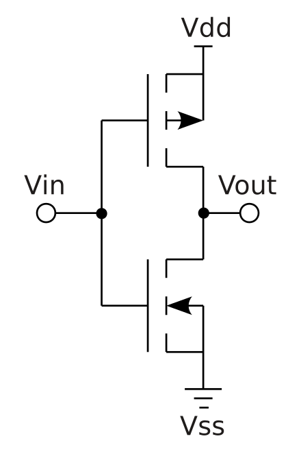
Currently, almost all ICs are CMOS-configured. CMOS is used in analog, as well as digital, applications, notably as analog sensors in digital cameras. The defining characteristic in CMOS digital devices is low power consumption. Because one of the series pairs is off while the other is on, the CMOS configuration draws very little current except during brief transitions during switching. Consequently, little heat is dissipated, permitting outstanding miniaturization and ultra-large-scale integration.
The CMOS operation consists of all p-type metal-oxide semiconductors having power from an input either from another p-MOS transistor or from the voltage source. Likewise, all n-MOS transistors have power either from another n-MOS transistor or from ground. In the p-MOS transistor, there is low resistance from source to drain when a low voltage is applied to the gate and high resistance when the gate sees high voltage. Current reduction, almost to zero, is achieved because n-MOSFETs and p-MOSFETs are in complementary configuration with both gates and both drains connected. High voltage applied to the gates causes the n-MOSFETs to conduct and the p-MOSFETs not to conduct, and a low voltage on the gates causes the reverse.
The gates are in parallel while the p- and n-MOSFETs are in series, which is why there is little current or heat dissipation except for very brief spikes at the transitions, which can be problematic, especially at high frequencies, due to RF interference elsewhere in the equipment or nearby. This can be mitigated by appropriately sized shielding.
If you’re going to work on digital circuits, it’s a sure thing you’ve got to have a working knowledge of logic gates. They may be idealized or physical devices. Both are based on the Boolean function, which is a logical operation realized as one or more binary inputs with a single binary output.
Logic gates are generally built using diodes or transistors. Alternate physical implementations are based on vacuum tubes, electromagnetic relays, fluid logic, pneumatic logic, optics and quantum entities. Multiplexers, registers, arithmetic logic units and computer memory are comprised principally of logic gates, of which there may be more than 100 million in one chip. Since the 1990s, most logic gates are made in CMOS technology, using n-MOS and p-MOS transistors.
The principal logic gates are:

Truth Table
- Input A: 0
- Output Q: 0
- Input A: 1
- Output Q: 1
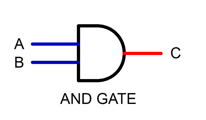
Truth Table
- Input A: 0
- Input B: 0
- Output Q: 0
- Input A: 0
- Input B: 1
- Output Q: 0
- Input A: 1
- Input B: 0
- Output Q: 0
- A: 1
- B: 1
- Output Q: 1

Truth Table
- Input A: 0
- Output Q: 1
- Input B: 1
- Output Q: 0

Truth Table
- Input A: 0
- Input B: 0
- Output Q: 1
- Input A: 1
- Input B: 0
- Output Q: 1
- Input A: 0
- Input B: 1
- Output Q: 1
- Input A: 1
- Input B: 1
- Output Q: 0

Truth Table
- Input A: 0
- Input B: 0
- Output Q: 0
- Input A: 1
- Input B: 0
- Output Q: 0
- Input A: 0
- Input B: 1
- Output Q: 0
- Input A: 1
- Input B: 1
- Output Q: 1

Truth Table
- Input A: 0
- Input B: 0
- Output Q: 0
- Input A: 1
- Input B: 0
- Output Q: 1
- Input A: 0
- Input B: 1
- Output Q: 1
- Input A: 1
- Input B: 1
- Output Q: 0

Truth Table
- Input A: 0
- Input B: 0
- Output Q: 1
- Input A: 1
- Input B: 0
- Output Q: 0
- Input A: 0
- Input B: 1
- Output Q: 0
- Input A: 1
- Input B: 1
- Output Q: 1
Notes:
- OR: Any high in will create a high output
- NOR: Any high in will create a low output
- AND: Any low in will create a low output
- NAND: Any low in will create a high output
A flip-flop has two other, less whimsical names, latch and bistable multivibrator. It is the basic building block of memory, and in its most fundamental binary form, it has two states: On (1) and Off (0). The flip-flop is further characterized by the fact that it can be made to change state by application of a signal to a control input. When powered down, the device remembers its previous state.
For all this functionality, the flip-flop can store only a single bit of 0 information. All of this is known as sequential logic. The device has many applications, including counting pulses and synchronizing variably timed input signals to a reference timing signal.
A flip-flop can be level-triggered or edge-triggered. Level-triggered flip-flops are asynchronous, while edge-triggered flip-flops are clocked. All flip-flops are comprised of gates.
Synchronous systems are necessarily clocked. The constituent flip-flops ignore their inputs, except at the transition of a clock signal or pulse. Then, the flip-flop either changes or retains its output signal, depending on the values of the input signals at the transition. They may reverse the output at either rising or falling clock edge.
The amplifier must be non-inverting. This can be accomplished by cascading an even number of inverting stages.
Common flip-flops are set-reset (SR), delay (D) and toggle. The simplest of these types is SR, which is constructed by two cross-connected NOR or NAND gates.
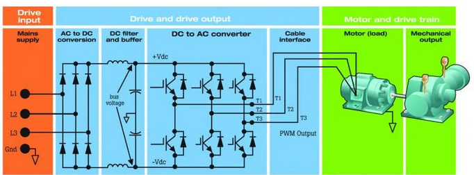
In elevator servicing, we’re often looking at the VFD-motor assembly. At the upstream and midsection of the VFD, rectifier and DC bus, the circuitry is analog. Finally, in the rectifier stage and on to the motor, it is digital. Some say that analog is easier to understand, while for others digital makes more sense. To work on the VFD-motor assembly, familiarity with both is required. The VFD is what is known as a mixed-signal device.
Let’s begin at the VFD input. The VFD and motor are generally located in the machine room unless the installation is machine-room-less, in which case the motor is located on top of the car and the locked motion controller and VFD are located in the top-floor corridor.
In any event, an electrical feeder with a disconnect enclosure is located within sight of the motor and switchable power is fed to the VFD. This power often consists of a 480-V, three-phase supply, which should be carefully measured by a non-contact voltmeter to ascertain that it is within 3% of the nominal voltage or 5% with the motor running fully loaded, if possible. Tools and procedures for safely working in the VFD are described in the following.
The rectifier section consists of six diodes and three capacitors, sometimes augmented by inductors. These components should be checked, evaluated and replaced as needed.
On a 480-V system, the DC bus conveys 1.414 times the line voltage, about 678 V. How is this possible? The simple answer is that the output from a full-wave rectifier is always higher than the input. What you are looking for is a nice, small, ripple-free DC if the inverter stage and motor are to function reliably. Check the DC bus with a hand-held, battery-powered oscilloscope or voltmeter in AC mode. These instruments should be sensitive to a small AC waveform riding on the high-voltage DC. If you see ripple, go back to the rectifier section and take a closer look at the capacitors and any inductor in the circuit.
Then, proceed to the inverter stage. Here, the main thing that is happening is that the straight DC voltage is converted to a pulsed DC of varying frequency and duty cycle that can regulate the speed of the AC motor.
Many VFDs have readouts that report a fault condition by means of an error code such as “F3,” which can be interpreted by consulting the VFD service manual. If the power supply or DC bus is malfunctioning, as outlined above, diagnosis is straight-forward. The inverter stage is a little more complex, and sometimes the quick and easy solution is to replace the circuit board(s). This may be quite expensive, but the priority in elevator repair is to get the system up and safely running as soon as possible.
In the inverter section, there may be some complications due to a proliferation of bells and whistles, which should be documented in the service manual. The basic system, however, is fairly easy to understand.
By way of background, for many decades, electric elevators used only DC motors, even after the introduction of Nikola Tesla’s three-phase AC induction motor. Rotation could be easily reversed by switching two of the three phase conductors, but speed control was much easier in a DC motor, where it was a simple matter of regulating the voltage to the motor. AC motor speed was problematic, because reducing voltage caused the motor to stall out and overheat. That is, until the 1960s, when the VFD was developed. It was then found that AC motor speed could be easily regulated, as required for smooth floor stops and operation in inspection mode, by adjusting the frequency and duty cycle in a square wave rather than just the voltage. The AC motor can even be run at higher than rated speed if high-speed bearings and adequate cooling are provided.
The VFD inverter section changes direct current from the DC bus to a square wave with adjustable frequency and/or duty cycle. Typically, the way it works is a control signal from the motion controller is applied to the control terminals of six solid-state MOSFETs known as thyristors. These are switching semiconductors that are capable of handling up to 2,000 V.
Two essential, very inexpensive tools for doing digital diagnostics are the digital logic probe and the digital pulser. The logic probe is a hand-held instrument with a needle-point electrode that can be touched to any point in a digital circuit. It detects the presence or absence of digital pulses and characterizes them by means of color-coded LED indicators. The pulser is another hand-held instrument with a needle-point electrode that can be touched to any point in a digital circuit. It is used to inject a digital signal to a wire or terminal that is not connected to an input signal input so that the effect of that circuit or component can be evaluated.
Specialized tools are required to work on and measure voltage and current in VFD motor assemblies. Depending on the voltage and available fault current, personal protective equipment may be needed, ranging from helmet, goggles and high-voltage gloves to complete suits. In an industrial or heavy commercial setting with a large bank of elevators, the equipment enclosure should be labeled with the voltage and available fault current. However, hazards may be present:
- The labeling may be out of date, i.e., the service and/or feeder(s) may have been upgraded, increasing the fault current without changing the labeling. Afterward, upgrade the labeling.
- It is always best to shut off power before approaching any high fault-current scenario.
- Even with power disconnected, hazardous voltages may be stored in component capacitors or in stray capacitance. This is especially true in the VFD rectifier section.
Unlike resistance, voltage and current can be measured only on energized circuits. Therefore, non-contact measuring tools are essential. Approach with care!
Learning-Reinforcement Questions
Use the below learning-reinforcement questions to study for the Continuing Education Assessment Exam available online at Elevator Books or on p. 117 of this issue.
- What is a mixed-signal system?
- What is pixelation?
- How do analog and digital domains differ?
- What is a MOSFET?
- What two types of MOSFETs are used in CMOS configuration?

Get more of Elevator World. Sign up for our free e-newsletter.
![]()


![]()