Early Electric Elevator Controllers, Part Two
Mar 1, 2015
Continued examination of a 1913 elevator catalog explains the technical operation of controllers, accessories and safeties, and sheds new light on the role of the elevator operator.
In 1913, Cutler-Hammer Manufacturing Co. of Milwaukee produced an extensive catalog of its products that provides a unique glimpse into the world of early electric elevators and controllers. The elevator portion of its catalog was composed of individual bulletins, which included 25 bulletins on controllers for DC motors, 15 bulletins on controllers for AC motors and 29 bulletins on accessories for electric elevator systems. Part One of this article (ELEVATOR WORLD, February 2015) provided an overview of controllers designed for use with DC motors and examined several of these controllers’ typical operational features and components. This concluding segment will address additional controller features, car equipment, the role of the operator, and the application of Cutler-Hammer controllers and equipment to elevator machines built by various regional companies.
The possibility or prospect of the elevator operator playing a role in elevator operation beyond simply “driving” the car was touched on in Part One. In the description of its “try-out switch,” Cutler-Hammer once again implied that the typical operator played an important role in ensuring efficient and safe elevator operation. The try-out switch was mounted on the face of the controller switchboard and was designed to permit the operation of the elevator from the machine room for “test purposes.” The switch consisted of a “single lever locked in the central position.” When in this position, it completed “the circuit to the car switch.” According to the author of Bulletin 7110, “Direct Current Reversible Two Speed Full Magnet Controllers for High Speed Passenger Elevators”:
“Operators are usually instructed to go to the switchboard every morning before entering the car and to test the operation of the elevator by means of the try-out switch, so as to be sure that every part of the installation is operating properly. In this way, the car can be run up and down the hatchway several times each morning, testing not only the controlling apparatus, but the motor, limit-switches, brake solenoids, etc.”
And, as it was “not possible to operate the elevator from the car while the try-out switch” was in use, the test runs could occur without risk to passengers. This proposed testing procedure implied the elevator operator would be sufficiently trained in the controller’s operation to effectively judge – by looking solely at the opening and closing of relays and switches – that “every part of the installation” was operating properly. Although it is probable that, in some settings, elevator operators were trained to do more than run the car, it seems unlikely they would have received technical training on controller operations.
However, another feature designed specifically for the elevator operator is more plausible in its possible use. Whereas the try-out switch was imagined as being used at the start of the day, the service switch, designed to take the elevator out of service, was primarily intended for use at the end of the day. Cutler-Hammer acknowledged the service switch was not a new feature; however, the company claimed the switch’s typical location was often problematic:
“It happens sometimes that the main line knife-switch ordinarily used as a service switch cannot be so located that it may be conveniently opened at night, or at other times when the elevator is idle for considerable periods. This condition is frequently met in buildings where the elevator machine is installed at the top of the hatchway, or on the roof, and unless some provision is made for opening the circuit to the motor from the car, or from one of the lower floors of the building, the operator will be obliged to leave the elevator at the top of [the] hatchway each night, walking downstairs every evening and upstairs every morning.”
The solution was to add “a main line solenoid switch with magnetic blow-out” to the controller. This switch acted as a “single-pole service switch” and remained closed while the elevator was in operation. The operator turned the service switch on and off via the car safety switch or “through any single-pole pilot switch installed on the landing at which the operator usually quits the elevator for the night.” The car safety switch consisted of “a single-pole switch enclosed in a cast iron box” and was intended to “ensure the stopping of the elevator even should some accident render the regular control from the car switch inoperative” (Figure 1).
The controller was also used to govern the operation of the elevator engine brake, which could be either a mechanical or dynamic (electric) brake system. Several types of Cutler-Hammer controllers were designed for elevators that employed both types of brake, as their combined use was perceived as complementary:
“In any form of elevator braking – mechanical or electric – the energy represented by the inertia of the moving parts must be dissipated in the form of heat in order to stop the motor. In mechanical braking, this energy is transformed into heat by the friction of the brake shoe. In electric braking, it is transformed into heat by causing the motor to generate current and dissipating this energy in a resistance provided for that purpose – the dynamic brake resistance. Hence, when the dynamic brake is used in connection with the mechanical brake, the effectiveness of the latter is increased, since it is not called upon to arrest a full-powered motor, but one which has already been deprived of a portion of its energy by having a resistance shunted across its armature terminals.”
The accessories referenced above, with the exception of the safety switch, were not the subjects of individual catalog bulletins. They were apparently considered normative controller features or options. The 29 bulletins on elevator controller accessories addressed such features as car safety switches, car-operation switches, limit switches, hatchway limit switches, slack-cable switches, elevator-door safety switches, floor stop devices and emergency-stop buttons.
The car-operation switch required the operator to maintain pressure on the control lever to run the elevator. The Cutler-Hammer switch featured a button on top of the control lever that was pressed to release the lever and that had to be continually pressed while the car was moving (Figure 2). If the operator released the button, the lever automatically returned to the center position, and the car stopped. This design ensured “constant watchfulness on the part of the operator” and served as “a safeguard against accident should injury or illness befall the operator while the car is in motion.”
Cutler-Hammer manufactured a variety of limit switches designed to be used in conjunction with the elevator winding drum; these included rotating-cam, traveling-cam, single-speed, two-speed, two-speed and slowdown, and track-type limit switches. A less-expensive option was the Cutler-Hammer hatchway limit switch that consisted of a “pivoted arm carrying a large roller at one end and a carbon contact button at the other,” which was mounted on a slate base (Figure 3). If the car failed to stop before it reached the switch, the roller would contact a cam on the car that pushed the roller back and opened the control circuit. The elevator-door safety switch prevented the elevator’s operation if the door were open. Cutler-Hammer reported, “This switch finds its widest application in connection with push button controlled elevators, but is sometimes installed, as an additional safeguard, in elevators operated by an attendant.”
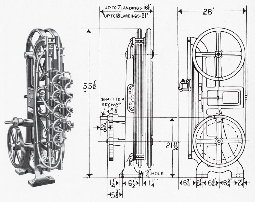
Cutler-Hammer also designed several devices intended for use with “push button controlled electric passenger elevators or dumbwaiters.” These included the floor-stop device and emergency-stop button. The operation of the floor-stop device (Figure 4) was described as follows:
“This device should preferably be geared directly to the winding drum on the elevator machine. . . . The operation of the floor stop device is positive. There is a relay for each floor, and this relay is actuated by a push-button properly marked. The relay, in operating, releases a catch, which drops a contact finger against one of two copper strips. These strips travel around the wheels on the floor stop device and are insulated from each other by a fiber ‘knock-out’ block, which resets the relay finger, and this stops the car. One of these strips makes contact with the ‘up’ reverse switch, while the other one makes contact with the ‘down’ reverse switch. The position of the ‘knock-out’ block on the floor stop device. . . corresponds to the position of the car in the hatchway.”
The emergency-stop button, connected to a “solenoid on the floor stop device,” was designed to “bring the car quickly to rest, at any point in its travel.”
Cutler-Hammer discussed almost all of the accessories addressed thus far in the context of controllers for DC motors. Although the company did build 14 types of controllers for AC motors (primarily utilized on belt-driven freight elevators, slow-speed passenger elevators and dumbwaiters), this system, while slowly gaining in popularity, was perceived as more limited in its potential:
“The alternating current induction motor is being used more and more for driving elevators, and, while admirably adapted for some classes of elevator service, it possesses certain definite limitations, which should be taken into account when deciding on what type of motor to use. It is not possible to vary the speed of the ordinary induction motor under all conditions of load, nor is it ever possible to employ with it the dynamic brake used with the direct current motor; hence, the use of alternating current motors is limited to slow speed elevators, which may be slowed down and stopped by the mechanical brake alone. Until. . . a variable speed alternating current motor is developed and placed on the market, the use of an induction motor with high speed passenger elevators should not be attempted.”
In addition to pictures of individual controllers and other components, several of the bulletins also featured pictures of elevator machines equipped with Cutler-Hammer controllers. The images of complete installations included machines built by Haughton Elevator Co. (Toledo), Marshall Elevator Co. (Pittsburgh), Nock & Garside Elevator Co. (Denver) and Bay State Elevator Co. (Agawam, Massachusetts) (Figures 5-8). The Haughton, Marshall and Nock & Garside machines all utilized Schureman-type controllers. The Haughton elevator used a Type 7565 Full-Magnet Reversing Elevator Controller (standing behind the electric motor), while the Marshall elevator employed a Type 7500 Semi-Mechanical Controller (mounted on top of the electric motor). The Nock & Garside machine was a ceiling-mounted, belt-driven freight elevator that employed a Type 7510 Single Speed Reversible Controller (located on a platform adjacent to the gearing). The Bay State elevator featured a Type 9828 Alternating Current Push Button Controller (mounted on the wall) and a Type 7085 Floor Stop Device (located to the left of the winding drum). The geographic diversity of the elevator companies represented – from Massachusetts to Colorado – speaks to Cutler-Hammer’s importance in the development and production of electric elevators.
This brief survey of Cutler-Hammer’s 1913 catalog bulletins has attempted to provide new insights into the operation of early electric elevators. The bulletins illustrate and explain the technical operation of controllers, accessories and safeties, and shed new light on (and prompt new questions about) the role of the elevator operator. Finally, this material also serves as a set of visual “keys,” which may be used to unlock part of the mystery of the machinery often depicted in photographs of historic elevators.
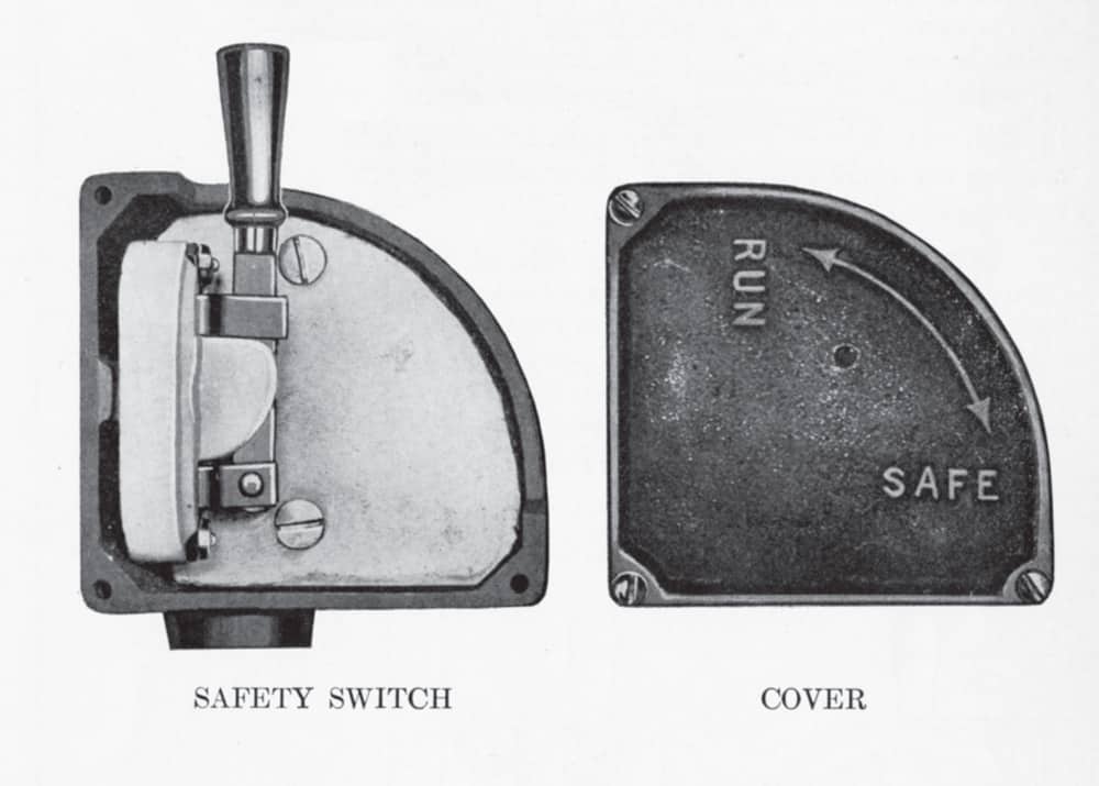
Figure 1: Car safety switch, Cutler-Hammer Bulletin 7790, “Elevator Car Safety Switch” 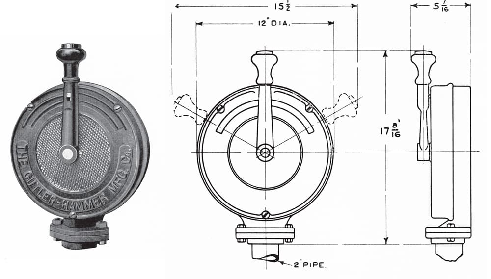
Figure 2: Car switch, Cutler-Hammer Bulletin 7730, “Elevator Car Switch – Cutler-Hammer Type” 
Figure 3: Hatchway limit switch, Cutler-Hammer Bulletin 7770, “Single Pole Hatchway Limit Switch – Cutler-Hammer Type” 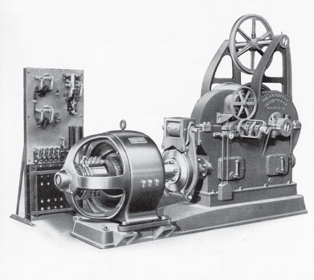
Figure 5: Tandem-gear winding-drum machine, Haughton Elevator, Cutler-Hammer Bulletin 7099, “Index and General Description: Direct Current Elevator Controller” 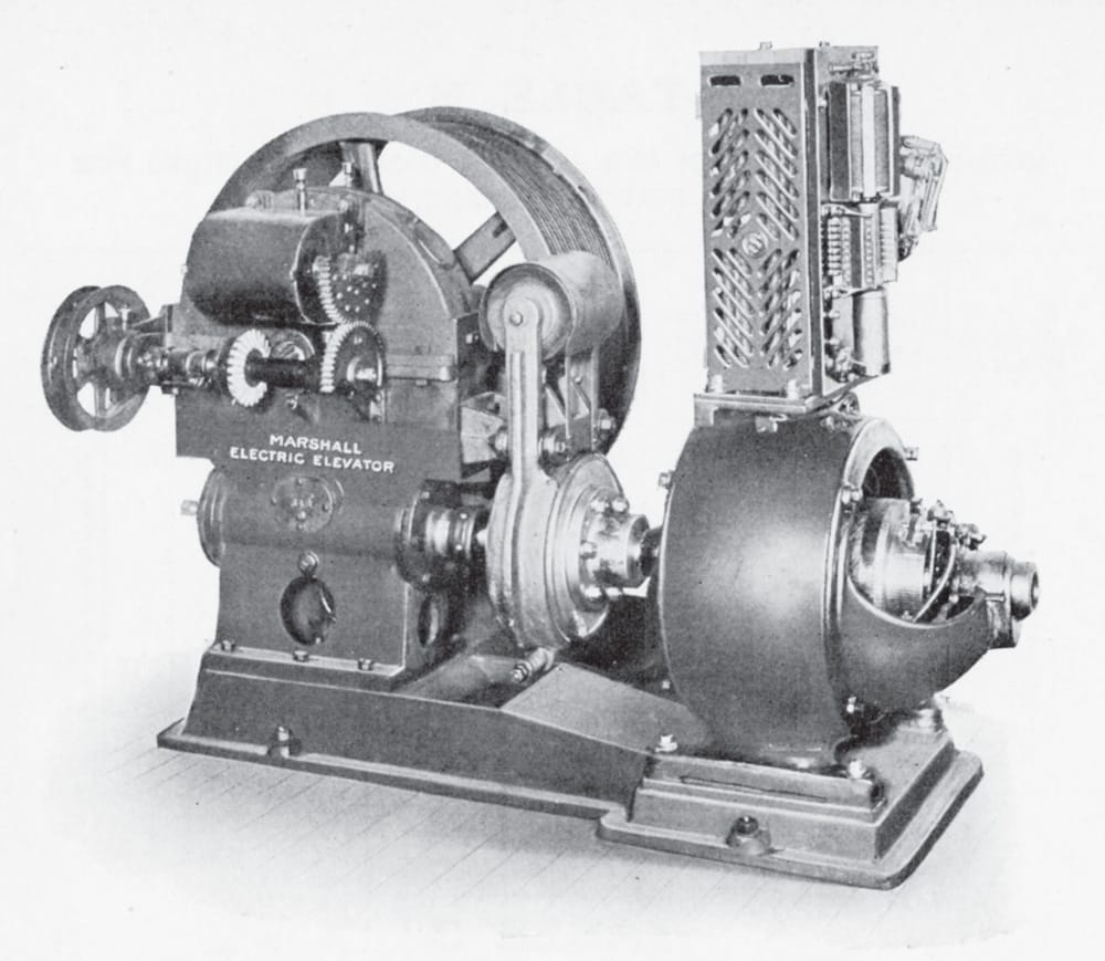
Figure 5: Tandem-gear winding-drum machine, HauFigure 6: Winding-drum machine, Marshall Elevator, Cutler-Hammer Bulletin 7099ghton Elevator, Cutler-Hammer Bulletin 7099, “Index and General Description: Direct Current Elevator Controller” 
Figure 7: Belt-driven machine, Nock & Garside Elevator, Cutler-Hammer Bulletin 7099 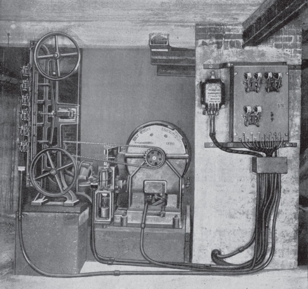
Figure 8: Push-button winding-drum machine, Bay State Elevator, Cutler-Hammer Bulletin 9699, “Index and General Description: Alternating Current Elevator Controllers”
Get more of Elevator World. Sign up for our free e-newsletter.

