Elasticity Behavior of Elevator Ropes
Jul 1, 2015

Demands are increasing due to a variety of factors.
by Dr.-Ing. Andreas Franz and Dipl.-Ing. Konrad Stahr
Increasing building/traveling heights, high-usage levels and modern system designs are among the factors increasing the demands on the physical properties of elevator suspension ropes. The trend toward saving cost and energy by reducing the size and weight of moving masses in regard to dynamic loads (e.g., drives and rotating parts) and static loads (e.g., cabs or car enclosures) further moves the operating point of modern suspension ropes into lower rope load ranges. An important consideration, in addition to rope minimum breaking force and rope service life (or bending fatigue performance) is the elasticity behavior of a rope under load.
Rope elasticity is directly related to the compressive deflection of the cab under load, and thus has a significant impact on the behavior and performance of the elevator installation (e.g., adjustment of leveling control, energy demand in multiple starts of the drive, service life and wear of drive components). Thus, it is directly related to the total cost of ownership, as well as the subjective perception of the passenger about system comfort (e.g., car movement during loading and unloading, releveling of cab, offset of hoistway landing and cab sills).
Rope elasticity is directly related to the compressive deflection of the cab under load, and, thus, has a significant impact on the behavior and performance of the elevator installation.
In overall elevator-system design, it is necessary to consider the elasticity behavior of the suspension ropes by making certain reasonable assumptions. This article will summarize possibilities for determining the rope modulus of elasticity according to current standards, describing characteristic phenomena regarding rope stiffness and reviewing the stiffness-optimized product options from the Gustav Wolf GmbH product portfolio.
Axial Modulus of Elasticity
Procedures and instructions for determining a rope’s modulus of elasticity in the longitudinal (axial) direction for wire ropes can be found in the International Standard ISO 12076,[1] as well as in the German technical guideline VDI 2358,[2] which has been revised in this regard. The test parameters of both sources already vary widely, so the guidelines have not yet fully penetrated production, market and application. There also exist, depending on the region, numerous user-specific approaches to determine the axial elasticity/stiffness, which takes into account the prevailing load of the wire rope in the application on a test basis.
The approaches to the pre-loading of the rope sample, as well as minimizing the rope’s inherent setting behavior (the components of the rope compress under load, which normally is a short-term phenomenon and stops soon after installation), already differ greatly between application requirements, as do clamping and testing conditions. This setting behavior can be pronouncedly different depending on rope design. Figure 1 illustrates the different approaches regarding the considered load area. In all approaches, the rope’s longitudinal modulus of elasticity is to be understood as the gradient of the force-elongation diagram, which is mostly calculated as a secant modulus between two single points of axially applied load (see dots in same color for respective approach of calculation).
The force-elongation behavior of every rope is always nonlinear, and it differs for loading and unloading (see green lines in Figure 1). Therefore, a secant or tangent modulus will always be a linear assumption/simplification of this behavior, which will be adequate for certain ranges of axial load. In Figure 1, by comparing the different slopes/pitches of the respective lines between two loading points (same color means same approach of calculation), it is clearly evident that sharply varying moduli may be derived for the same rope. Moreover, as a rule of thumb, the rope modulus may be understood as rising with the amount of rope force related to the rope’s breaking force.
The differences in rope modulus may be illustrated by comparing the curve pitches directly after parallel translation (see the upper left corner of Figure 1). It should be noted that the three calculated rope moduli of elasticity mentioned in Figure 1 may differ from 60,000 N/mm2 to 110,000 N/mm2. Keeping in mind that exactly the same rope evaluated is represented by this figure, it becomes evident that just a statement on rope stiffness in regard to modulus does not necessarily reflect the behavior of the elevator car under load.
Gustav Wolf can provide its customers the necessary elongation and elasticity characteristics based on application parameters provided by the customer.
Often utilized as a measure of rope performance, Figure 1 intends to show the incomparability of different approaches of calculation and the importance of stating how the modulus of elasticity is being determined for the actual rope product by the rope manufacturer, user or third party. To determine the elongation/stiffness behavior in the application itself, it is useful to evaluate the load and time-dependent behavior of the respective rope under different application-related conditions. For elevator ropes, a close coordination between rope users and manufacturers is helpful. Gustav Wolf can provide its customers the necessary elongation and elasticity characteristics based on application parameters provided by the customer.
Time-Dependent Behavior of Axial Modulus of Elasticity
The rope modulus is not a quantitative value that is constantly available immediately after installation of the rope. Instead, the rope structure is subject to a setting behavior. After the setting has taken place, specific rope stiffness is constantly present in a certain load range. The fact that a rope labeled “pre-stretched” is used has no significant influence on this behavior.
Knowledge with respect to time dependency and the expression of this phenomenon for different rope types and designs is crucial to the design and evaluation of elevator behavior for the elevator manufacturer. Figure 2 illustrates the rope elastic modulus between 2% and 10% of the rope’s minimum breaking strength (range of typical load conditions for elevator ropes conforming to Figure 1) as a function of the number of axial load cycles. All elastic moduli were related to the final adjusting value of the respective type of rope so that quantitative differences regarding the rope modulus of elasticity of the rope types evaluated (Figure 4) at this point are deliberately not considered.
Clearly visible is the dependence of the adjusting modulus of elasticity as a function of cycles of axial load for the different rope designs. While suspension ropes with natural and synthetic fiber cores initially exhibit a significantly reduced rope stiffness and, therefore, modulus (about 50-60% of the final modulus) and comparatively slowly approach their final stiffness, after just a few load cycles, the full-steel ropes reach their final rope stiffness.
The worldwide trend toward construction of higher buildings requires longer elevator ropes.
The full-steel wire ropes also already exhibit a rope stiffness of about 80-90% of the final stiffness in the first load cycle. Differences can be seen both in the type of fiber core (natural versus synthetic), as well as in the type of rope structure (compaction versus parallel lay). For suspension ropes with natural fiber cores, no significant influence of compaction of the outer strands could be identified in terms of dynamic behavior regarding rope modulus of elasticity. In ropes with high-strength synthetic fiber cores, the setting behavior can be more pronounced, so a longer setting period may be necessary. Of course, the results shown in Figure 2 are dependent on the actual cyclic load applied in testing or application.
Stiffness-Optimized Rope Designs
The worldwide trend toward construction of higher buildings requires longer elevator ropes. With it, the elongation, respectively, of the axial modulus of elasticity in the specific operating range of the utilized ropes takes on a bigger impact. In elevator applications, steel wire ropes with fiber core constructions of 8 X 19 Seale or 8 X 19 Warrington are commonly used. To the extent demands on ropes increase, there is a concurrent availability of more and more special ropes with eight or nine strands and full-steel cores.
Most commonly, ropes with natural fiber cores exhibit a lower axial modulus of elasticity and, therefore, stiffness than ropes with full-steel cores. However, for ropes with fiber cores, this characteristic feature may be increased. On the one hand, this can be reached by a flattening of the outer wires/strands as carried out for Gustav Wolf CompactTracTM[3] with a substitution of the natural fiber cores by a high-modulus, high-strength synthetic fiber core as with Gustav Wolf HyTrac.TM[4] Figure 3 summarizes the performance of Gustav Wolf’s rope types in terms of the ropes’ axial stiffness, minimum breaking force and bending fatigue lifetime to better provide for application-specific use.
The result of application-oriented R&D in response to the increased demands of elevator systems can be found in Gustav Wolf’s Trac series, consisting of the CompactTrac, HyTrac, PowerTrac™ and TopTrac™ (Figures 3 and 4).
All Trac series ropes distinguish themselves by exhibiting improvements in the following areas:
- Minimized rope elongation and respectively higher rope modulus of elasticity
- Longer rope service life due to more bending cycles
- Improved wear resistance due to the enlarged contact area of the outer strands
- Reduced rope diameters based on higher breaking forces
With the Trac series, Gustav Wolf has developed a new generation of elevator ropes which distinguish themselves with improved stiffness behavior, longer service life, improved system performance and, most importantly, a higher level of customer satisfaction. They should be considered as a solution for the ever-increasing demands of elevator systems and, in particular, for high-rise installations.
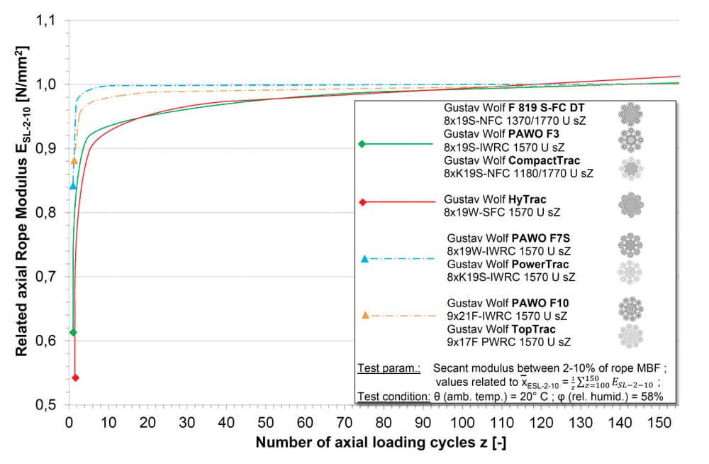
Figure 2: Longitudinal modulus of elasticity in the work area of elevator ropes depending on the number of cyclic applications of axial load 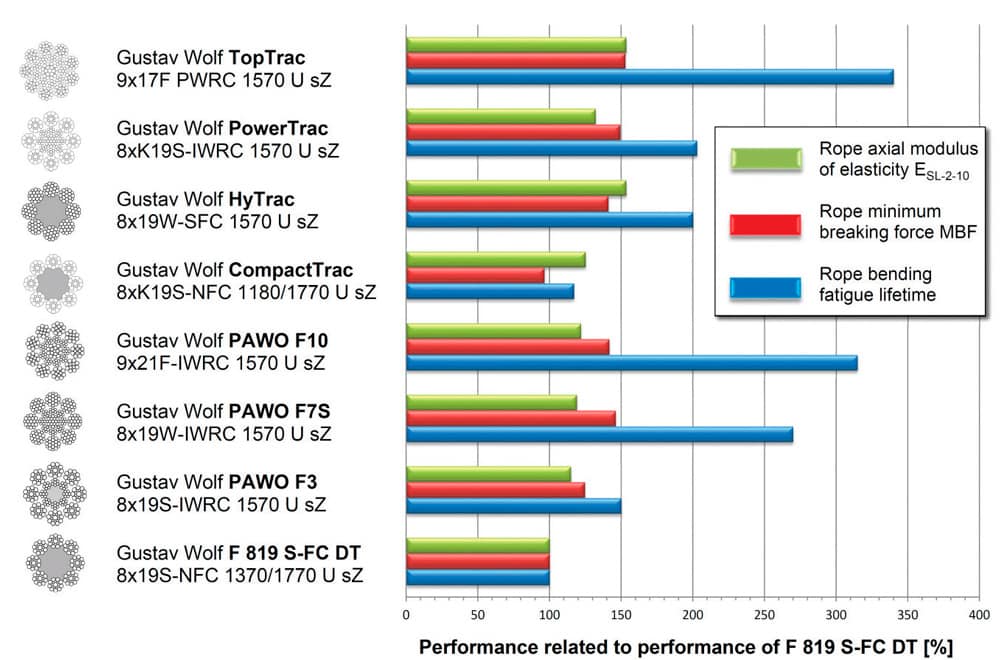
Figure 3: Performance of Gustav Wolf ropes in terms of ropes’ axial stiffness, minimum breaking force and bending fatigue lifetime 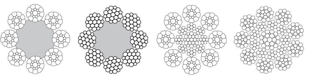
Figure 4: Gustav Wolf’s Trac series consists of (l-r) CompactTrac, HyTrac, PowerTrac and TopTrac.
References
[1] ISO: ISO 12076:2002, “Steel Wire Ropes – Determination of the Actual Modulus of Elasticity,” 2002.
[2] VDI: Verein Deutscher Ingenieure (VDI): Richtlinie VDI 2358 – Drahtseile für Fördermittel, Beuth Verlag GmbH, 1984.
[3] Wolf E. Franz, A., “Rope Development for Elevators,”
ELEVATOR WORLD, March 2006.
[4] Franz, A., “Development of Hybrid Rope for Elevators,”
EW, July 2012.
Get more of Elevator World. Sign up for our free e-newsletter.


