Electrical Parameters
Aug 6, 2022
A review of the fundamentals and the subtle ways in which they interact

Value: 1 contact hour (0.1 CEU)
This article is approved for Continuing Education by NAEC for CET® and CAT®.
EW Continuing Education is currently approved in the following states: AL, AR CO, FL, GA, IL, IN, KY, MD, MO, MS, MT, NJ, OK, PA, UT, VA, VT, WA, WI and WV | Canadian Province of BC & ON. Please check for specific course verification of approval at Elevator Books.
Learning Objectives
After reading this article, you should have learned:
- What are the most basic electrical parameters?
- What does amps times volts equal?
- What does Kirchhoff’s Current Law state?
- How many conductors are required to measure current in a clamp-on ammeter?
- What is the advantage of a non-contact voltmeter?
In this article, we discuss the basic electrical parameters, volts, amps, electrical charge, capacitance, inductance and ohms. All electronic technicians, particularly elevator technicians and maintenance workers, know the fundamentals, but there are some subtleties in how they interact that are worth reviewing.
To work on electrical equipment, particularly elevators, in design and manufacturing or diagnostics and repair, a precise knowledge of electrical parameters is required. The most basic of these are amps, volts, ohms and coulombs.
The amp is the unit of electrical current, beginning in the battery electrolyte or the windings in an electrical generator, flowing through conductors, through the load and back to the source. Throughout this circuit, unless it splits into separate branches, the current is the same, in accordance with Kirchhoff’s current law. This is a very basic principle in electronics, and it is enormously helpful in preliminary diagnostics. All those electrons have to go somewhere, and they are not lost, even when passing through a resistive load where a portion of the energy is dissipated as heat. (It is power that is dissipated, not current.)
One amp, by definition, consists of a flow of 6.24 X 10¹⁸ electrons moving past a specific point in an electrical circuit per second. (That’s 624 followed by 18 zeros. If you don’t understand, look up scientific notation on the internet.) This figure is absolutely accurate because it is fixed by definition. Definitions of the other electrical parameters are derived from the definition of the amp.
Since the amp is a measure of flow of current through a conductive body, it is improper to speak of electrical current as being a property of the source except that any source has a maximum available current, which increases rapidly when the resistance or impedance of the load is lowered below a critical value.
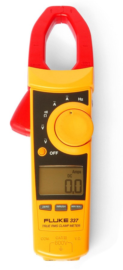
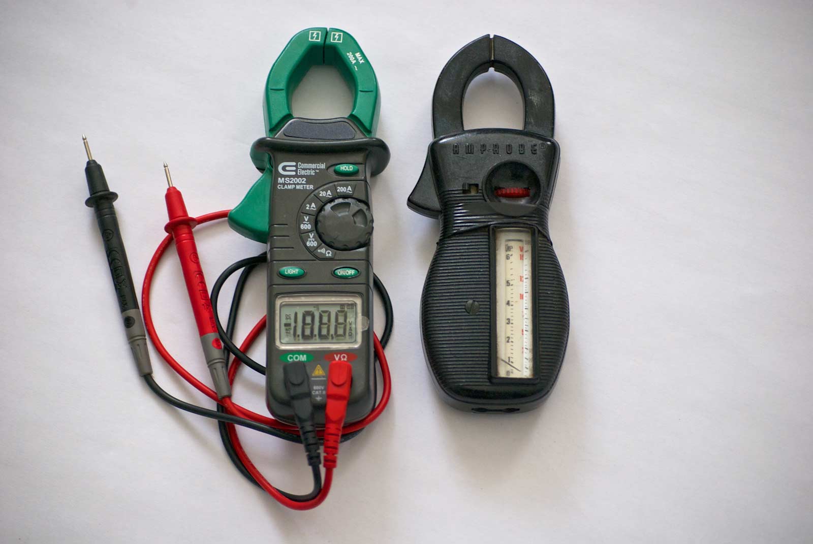
Electricians use a current clamp to measure current drawn by heavy loads such as an elevator motor. Pressing the thumb switch on the side of the instrument, the jaws open and can be closed around a live conductor, bare or insulated. The display shows the current in amps flowing though the circuit. The measurement can be performed on a conductor that is feeding operating equipment such as an elevator motor, without taking it out of service.
The live conductor and the jaws of the instrument are the primary and secondary of a transformer. This measures the magnetic field around the conductor, and the display is calibrated to show amps. Even though the Amprobe is in essence a transformer, advanced models can read direct current by means of an internal Hall effect device.
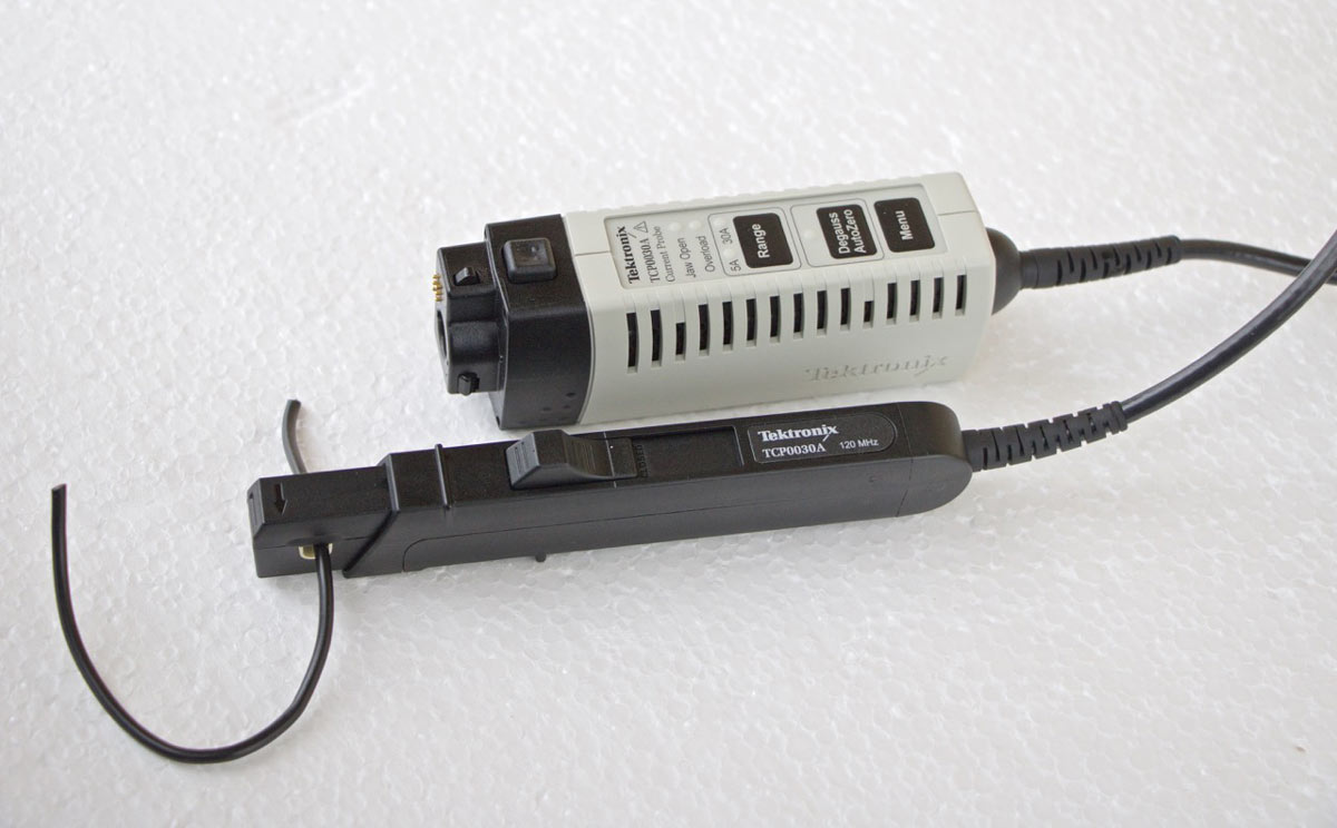
The current clamp is capable of measuring 200-600 amps. It doesn’t work on cables containing two or more conductors because the currents flowing through them are traveling in opposite directions and the magnetic fields cancel one another.
Small amounts of current can be read in a multimeter. It is necessary to cut open the circuit under test and place the meter in series. Then, after taking the measurement, re-solder the circuit. Be sure to check the rating of the multimeter in the amps mode because the meter will not tolerate an overload. Remember that when taking this type of reading, as opposed to a clamp-on ammeter, voltmeter or ohmmeter reading, the full amount of current goes through the meter.
The volt is the unit of electromotive force. By definition, it is the electric potential between two conductors or terminals when one amp of current flows through the circuit. When a load is not connected, this one amp of current does not flow through the circuit, but that does not negate the definition of volt. Alternately, we can say that one volt is the potential difference between two wires or terminals when one joule of energy per coulomb of charge passes through the circuit. It is improper to speak of a voltage passing through a circuit just as it is improper to speak of a given current on a terminal.
Note the following relations:
- Volts equal amps times ohms
- Volts equal webers per second (magnetic flux per time)
- Volts equal joules per coulomb
Since voltage is a difference in potential, it is usually measured by using a multimeter within its rating to probe across a live component, two points in a circuit or one point in a circuit and ground. It is important to operate the meter within its rated voltage. If the voltage is not known, it is often safe to assume the voltage does not exceed the supply voltage, although this may not be true as in a variable-frequency drive for an elevator motor or equipment such as a TV cathode-ray tube with high deflection voltages, or anywhere there is a step-up transformer.
For a comprehensive understanding of electron volts and how they unite the concepts of voltage and charge, we have to discuss the electron volt (eV), which has historically been used by theoreticians and researchers. The eV is a very small energy potential. A trillion eVs is roughly the energy expended by a flying mosquito. That need not trouble us, however, because using scientific notation or prefixes, the eV can be brought up to, let’s say, the amount of energy to power an elevator of any size. One hundred seventy-two GeV is the rest energy of a top quark, the heaviest measured elementary particle.
In physics, an eV is the amount of kinetic energy gained by a single electron accelerating from rest through an electric potential difference of one volt in a vacuum. Used as a unit of energy, the value of 1 eV in joules is equal to the numerical amount of charge of an electron in coulombs.
This brings us to the important concept of charge. Electric charge is measured in coulombs. In working on elevator diagnostics and design, you will rarely need to measure charge, but the concept is important in the motor circuit and the controller, particularly for what is going on in metal-oxide semiconductor field-effect transistors (MOSFETs).
Ancient writers were acquainted with five distinct phenomena, which we explain using the concept of electric charge:
- Lightning
- Electric eels and torpedo fish
- St. Elmo’s fire
- Amber, rubbed with fur, which attracts small objects
- Static electricity, as when a spark jumps from one’s hand to a metal object
Thales of Miletus (624-546 BC) left no extant writings, but it is said that he described the amber effect, which he stated as proof that inanimate objects have souls.
Generally speaking, the ancient Greeks did not appear to be aware that the five categories listed above were in any way connected. Greek experimenters observed that charged amber would attract light objects, and they observed that rubbed amber could produce a faint electric arc.
More detailed analysis occurred in 1600 A.D., in William Gilbert’s De Magnete. This English scientist coined the word “electrica” to describe the amber effect.
In the next two centuries, scientists including Benjamin Franklin developed more sophisticated two- and then one-fluid theories of electric charge. Franklin visualized electricity as an invisible fluid present in all matter. He stated that it was the glass in the recently invented Leydon jar that held an accumulated electric charge. He believed that rubbing insulated surfaces together caused the fluid to move from one location to the other, constituting an electric current. He stated that when matter contained an excess of the fluid, it was positively charged and when it had a deficit it was negatively charged. He got the dynamics right but was wrong about the direction of flow. To this day, we say that an electron has negative charge, although there is nothing inherently negative about it.
CAT Protection
In addition to the meter’s overload ratings, it is essential to comply with the CAT ratings, which are invariably printed on the front panel or face of electric meters and instrumentation, adjacent to the input ports. These CAT ratings are entirely separate from and much higher than the maximum voltage ratings. These ratings apply to hand-held instruments, such as the multimeter, as well as bench-type instruments, such as the oscilloscope and spectrum analyzer. The CAT ratings tell you the maximum voltage that is safe to probe in each of four categories of locations. The locations were originally identified by the IEC in Europe and subsequently adopted in the U.S., where they appear in UL 61010B-1 and C22.2 No. 1010.1. The four locations are:
- CAT I – Signal-level tools for telecommunications and electronic equipment.
- CAT II – Circuits for fixed or non-fixed power devices, including most lighting equipment, appliances and 120V and 240V equipment inside a building.
- CAT III – Most distribution circuits, including fixed primary feeders and branch circuits. They are separated from CAT IV utility service or other high-voltage source equipment by transformer isolation or sufficient vertical separation.
- CAT IV – The primary supply source, including 120V or 240V overhead or underground lines that power detached buildings or underground well pumps.
So, the first step is to choose an appropriate measuring instrument with sufficient overload protection for the contemplated measurement. Then consult the instrument’s CAT rating and maximum allowed voltage. (There may be more than one CAT rating).
In 1838, Michael Faraday began a detailed study of electric charge. He observed that electric charge is a relation between two material bodies because it is impossible to charge one body without imparting the opposite charge to another material body. Accordingly, electric charge is a deficit or excess of electrons or other charge carriers. Furthermore, he concluded that the normal state of particles is to be non-polarized. When polarized, these particles tend to return to their non-polarized state.
Two decades later, James Clerk Maxwell realized that charge, rather than a substance, is energy that resides in the field between two charged substances. We see this in the behavior of a capacitor. A capacitor consists of two conductive plates with leads attached, separated by a thin layer of non-conductive material known as the dielectric layer. When voltage is applied to the plates of a capacitor, contrary to common belief, current does not flow through it, as in a resistor. That is why capacitors do not dissipate much heat despite the voltage drop that can be measured across them when energized. Where does this energy go? The charge is stored in the dielectric layer, then, when the applied voltage is removed, the voltage returns to the connected circuit. Thus, the function of the dielectric layer is not only to hold the plates apart and to electrically insulate them from one another but also to store the electric charge. This process continues until a state of equilibrium is reached. Then, if an opposite polarity is applied, the dielectric is discharged and then charges to that opposite polarity. This happens very quickly if AC, especially high frequency, is applied.
To the outside observer, this appears as current flow, but actually it is the dielectric layer storing and releasing charge carriers.
An inductor (coil) works in a similar way, except that the energy is contained in the area surrounding and within the coil in a magnetic field. When the current to the inductor is interrupted, the magnetic field is said to collapse and the energy is returned to the windings that comprise the coil. When DC is applied to an inductor, there is a brief high-voltage spike across it, and another spike when the voltage is removed.
Electric charge is quantized. It exists only in integer multiples of what we call e, which is very small, equal to 1.62 X 10⁻¹⁹ coulombs.
The unit of charge is the coulomb. It is defined as the amount of charge that passes a specified point on an electrical conductor carrying one ampere of current in one second.
In the ordinary course of circuit diagnosis or prototyping, workers rarely need to measure charge since it is the integral of amperage and current and is easily measured with a multimeter in amps mode or with a clamp-on ammeter. If charge must be measured directly, use an electrometer or ballistic galvanometer.
Another very fundamental electrical parameter is the ohm. It is the unit of electrical resistance, a property of any material, including vacuum, that is capable of conducting charge carriers.
In popular imagination, when voltage from a source such as battery or generator is applied across a conductor, the electrons line up at the negatively charged end and travel at the speed of light to the positive end, to which they are attracted, and then return to the power source. In reality, their journey is much slower and their motion more random. They are subject to collisions with atoms, ions and free electrons in the conductor. This constitutes resistance, which causes a portion of the electrons to be radiated and dissipated as heat.
It is this resistance that is measured by means of the multimeter in ohms mode. Resistance is measured on a daily basis by electricians and electronics technicians. Unlike amps and volts, it is not a live measurement. If you wish to measure resistance of an in-circuit component, as in a printed circuit board in an elevator motion controller, first make sure that the equipment is powered down. Unexpected voltage applied to the leads of an ohmmeter can destroy the meter and injure the user if the voltage and/or fault current is sufficiently high. Beware also that equipment with electrolytic capacitors such as a power supply can store residual voltage long after it is powered down. There is also such a thing as distributed capacitance throughout the chassis. For this reason, it is best to cut one lead, using an insulated cutting tool within its rating and high-voltage gloves (available from Amazon) where appropriate.
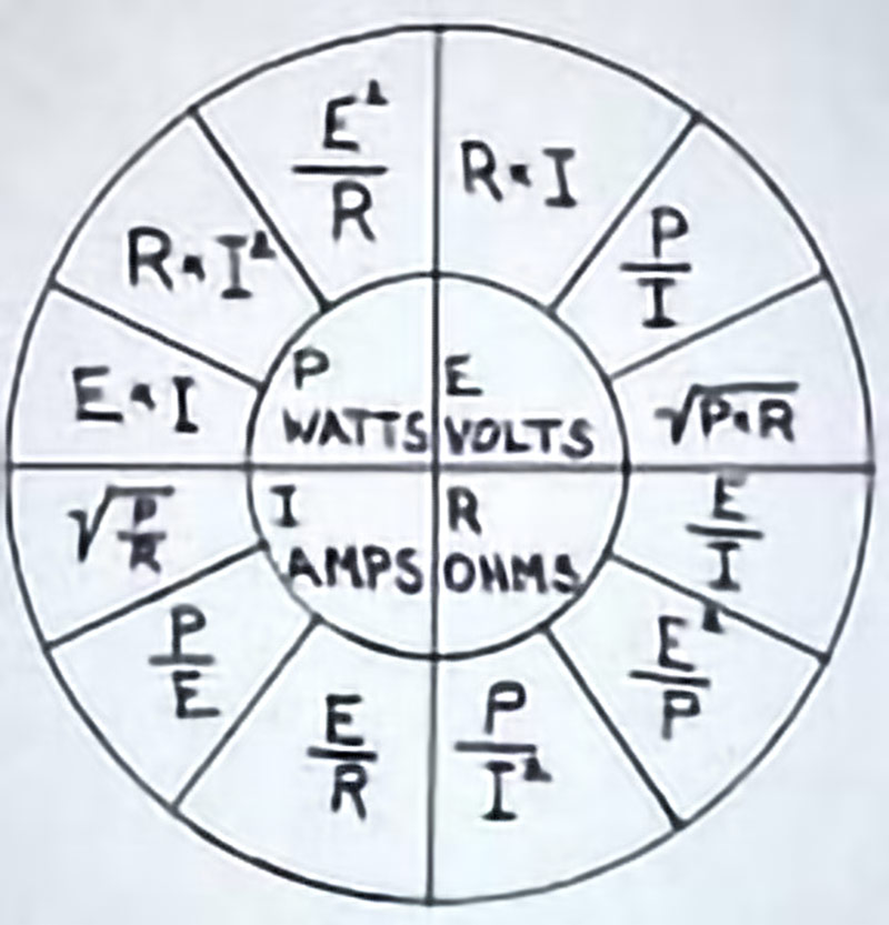
The resistance R of a body is the ratio of voltage V across it to current I through it. Conductance G is the reciprocal, as expressed in these equations:
- R = V/I
- G = I/R
- G = I/V
These equalities constitute Ohm’s law. They are applicable to ohmic materials, but not to certain devices such as a battery, diode or transformer, which have intrinsic properties that obscure the ohmic parameters.
Resistance and conductance of a body are primarily determined by its geometry and constituent material. Geometry affects resistance as in a long, thin wire, which has a higher resistance than a short, thick wire of the same material. Material is the other factor. Electric current flows with little loss through copper wire, while with greater loss through steel wire of the same thickness and length. The wide range in their properties is known as resistivity. The resistivity of a given material is constant regardless of its size, shape or configuration within a circuit. The resistivity of a box of wire in the warehouse is the same as the resistivity of a short jumper on a printed circuit board, given the same wire material. But resistance is dependent on resistivity, shape and size. Additional factors, other than shape, size and resistivity, such as temperature and strain, also impact the resistance of a conductor or device in an electrical circuit, although at the most basic level of motion controller and variable speed drive diagnostics, these effects do not have to be considered, unless subtle conditions are suspected.
The resistance across most bodies of the same size, shape and resistivity is constant. But resistivity of different materials varies enormously. For example, the conductivity of Teflon, a good insulator, is 1030 lower than copper. This is because the electrons in an insulator are bound in specific locations and therefore unable to carry charges from one end of the material to the other end. In contrast, conductors such as metals have far more free electrons that are not bound in place to atoms, but are able to travel freely through the relatively vast spaces between the atoms. Most materials, such as carbon, have an intermediate resistivity. Most resistors are manufactured by mixing various proportions of pulverized carbon with a paste having different resistivity.
Superconductors may be the wave of the future, especially in low-temperature outer space. Superconductors are made of materials that have close to zero resistivity (infinite conductivity) if cooled sufficiently. Consequently, there is almost no dissipation of electrical energy, no appreciable loss. What is problematic is that, at this point in time, metallic conductors have to be cooled using liquid helium to about 4° K to function as superconductors.
Advanced systems have been developed that function at 77° K. They work with the far less costly liquid nitrogen coolant, but the materials are more expensive, brittle and fragile ceramics, which are not practical. Because metallic superconductors require difficult coolants, notably liquid helium, there is a great incentive for researchers to discover better high-temperature materials, meaning those that become superconducting at the temperature of user-friendly liquid nitrogen.
So far, what has been found are copper oxides and iron-based compounds. Unfortunately, these materials do not lend themselves to being formed into workable conductors. A promising area is in superconducting gasses, but, so far, this is mostly speculative.
Low-temperature superconductors are used in specialized applications, such as particle colliders, which require large, very low-resistance conductors to power huge magnets that speed the particles on their way.
Learning-Reinforcement Questions
Use the below learning-reinforcement questions to study for the Continuing Education Assessment Exam available online at Elevator Books or on p. 133 of this issue.
- What are the most basic electrical parameters?
- What does amps times volts equal?
- What does Kirchhoff’s Current Law state?
- How many conductors are required to measure current in a clamp-on ammeter?
- What is the advantage of a non-contact voltmeter?
Get more of Elevator World. Sign up for our free e-newsletter.


