Electrically Assisted Braking Using DC Hoist Motors
Feb 1, 2011
This article explores some of the issues related to braking performance on the emergency stopping of elevators.
by Nick Marchitto
This article explores some of the issues related to braking performance on the emergency stopping of elevators.
Electrically Assisted Braking Using DC Hoist Motors
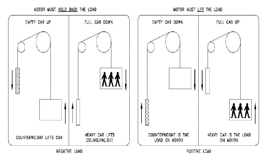
DC motors have the capability of regenerating energy when operating in the overhauling (negative-load) condition (i.e., driven by the load –Figure 1). The DC hoist motor acts like a generator if it has motor field excitation and sufficient mechanical power is turning its motor shaft. Examples of overhauling conditions which, in turn (being mechanically coupled to the AC driving motor of the MG set), drives the AC driving motor as an alternator, pumping power back into the AC lines. If the AC driving motor is driven above its rated synchronous speed, it will provide regenerative braking and attempt to hold back the elevator load (limit any speed increase of the DC hoist motor) and hence limit the car speed. This operation can occur as long as the loop circuit is not opened and the MG set AC driving motor remains connected to the AC line. (Mainline disconnect or fusing is not opened.) Damping of the generator fields is also provided to slow the response of the generator and provide smoother regenerative braking. Some Ward Leonard elevator control designs open the loop circuit when making an e-stop and while the elevator is idle at a landing, disabling the regenerative path but providing dynamic braking instead.
Learning Objectives
After reading this article, you should have learned:
♦ Elevator AC and DC motors, when applied to several different types of drive/control designs, have the capability of regenerating electrical energy.
♦ The regeneration of electrical energy can provide a “braking torque” from both an AC and a DC motor to decelerate the mechanical load on the motor shaft.
♦ For DC control, the typical designs of the “loop circuit” and the effects on emergency stopping when the loop circuit is kept closed and it is opened during the stop
♦ The difference between regenerative and dynamic braking as applied to both AC and DC motors/drives/control systems
♦ The control methods by which elevator AC motors can provide a braking torque
♦ During typical elevator emergency stops (e-stops), both the elevator machine brake and the regenerative or dynamic braking contribute to the total braking effort on the system.
♦ The sequence of events during a typical e-stop.
♦ That there are many elevator system parameters in play at the time of the e-stop, and that they influence the deceleration rate of the stop.
♦ There can be mechanical and electrical design conflicts for emergency stop braking systems when considering balancing ride quality issues during the stop with the effectiveness of making the stop.
♦ Looking forward, there are many design challenges to develop the optimum elevator braking systems that provide acceptable performance during an e-stop under all elevator operating conditions.
For DC-SCR (thyristor) drives using a “dual converter,” regeneration back to the AC power source (building AC lines) is possible as long as the DC loop circuit is not opened. However, the ASME A17.1/CSA B44 code requires that two means to disconnect power from a DC hoist motor
supplied by a DC-SCR drive are furnished. One means must either be via contactor(s) or an electrical/electronic/programmable electronic system (E/E/PES) with a safety integrity level (SIL) not less than the highest SIL of the electrical protective device (EPD) involved in the removal of power from the DC hoist motor. In some control designs, these contactor(s) or SIL devices open the loop circuit; others open the AC feed to the input of the DC-SCR drive (Figure 3). Regardless as to how this is implemented, the regenerative path is disabled, and regenerative energy cannot flow back to the AC lines during an e-stop.
Dynamic braking may be used to overcome the loss of regenerative braking whenever the loop circuit is opened. Dynamic braking is obtained by virtue of the elevator hoist motor acting as a generator (if the motor field is kept energized) and by dissipating the system mechanical energy as heat in the dynamic braking resistors (DBRs). A low value of resistance is inserted across the DC hoist-motor armature when the loop circuit is opened. The DBRs are automatically connected when required by using the “back” or “breaking” power pole contact(s) of the contactor(s) that open the loop circuit (normally open contacts “DD” in Figure 3).
The value of dynamic braking resistance (DBR) is chosen to set the amount of braking torque that the DC hoist motor provides during dynamic braking. The initial amount of DC current is calculated using Ohm’s Law (I = E/R). Note that the current will decrease as the generated voltage (E) from the hoist motor decreases with decreasing motor rotations per minute (RPM) during the stop, and also somewhat as the DBR value (R) increases with resistor heating during the current flow through the resistors. The lower the DBR, the more initial DC current will flow, and the greater the overall braking torque that will be applied by the DC hoist motor. A DBR too low, approaching that of a short circuit across the DC hoist motor armature, will result in the maximum current and maximum braking torque, possibly causing damage to the DC hoist-motor commutator and brushes. An almost instantaneous stopping of the motor armature (causing a loss of rope traction on the driving sheave) will result. This can cause wear of the suspension ropes and driving-machine sheave grooves. There is also the possibility of shafts and/or couplings and other machine components being mechanically over stressed and damaged.
When the loss of AC line voltage due to a utility or building power outage occurs, the elevator will automatically make an e-stop. The DC hoist-motor field excitation from the controller supply will decay upon the loss of AC line power, preventing any effective dynamic braking. For low-speed elevators, the car is well on its way to stopping by the time the motor field collapses. For higher-speed elevators, a motor field “hold-up” circuit may be used to maintain the motor-field excitation during all or most of the e-stop. The DC hoist-motor field is “self excited” by having the motor field circuit fed through steering diodes and contacts X and Y to supply the correct polarity from the armature output voltage during the e-stop (Figure 4).
For DC-SCR drive designs that open the AC feed to the DC-SCR drive, the dynamic braking could be implemented (with careful interlocking of operating modes) using a contactor or solid-state switching device to insert a resistor across the DC hoist motor armature. This operation would occur while the motor remains connected to the DC-SCR drive, but this is not often done, since such drive systems are usually applied to low-speed, low-capacity elevator duties where the mechanical machine brake is capable of absorbing all of the stopping energy.
For DC-pulse width modulated (PWM) drives, a fully regenerative bridge provides DC to the hoist motor. DC contactors are furnished to disconnect the DC hoist motor from the drive and insert DBRs that provide the DC hoist-motor braking torque. For higher-speed elevators, a motor-field hold-up circuit maintains the motor-field excitation during the e-stop.
Electrically Assisted Braking Using AC Hoist Motors
AC elevator hoist motors can regenerate power when operating in the overhauling condition (i.e., when driven by the load such that the motor is driven above its synchronous speed, while it is connected to the AC line). The higher the motor speed is above synchronous speed, the greater the available motor braking torque. This condition exists up to the pull-out or breakdown torque point in the above-synchronous speed region of motor operation. The pullout or breakdown torque is the maximum torque capability of the AC motor and occurs at a speed well below the synchronous speed (typically, at start, around 0-10% of synchronous speed for AC elevator NEMA D type motors used with single- and two-speed AC resistance control) when operating in the motoring mode, and in a “mirror image” above the synchronous speed when operating in the motor-braking mode.
Single- and two-speed AC motor control and AC resistance control (Figure 5) typically stop the elevator on the brake for both normal and emergency stopping. Two-speed motors provide some electrical braking during the transition from high to low speed. During the switching from the high-speed winding, at the time that the low-speed winding is being connected to the AC power supply, the actual motor RPM is above the low-speed winding synchronous speed, and some motor braking torque is generated as described above until the motor RPM drops below its low-speed winding synchronous speed.
Some variable-voltage (ACVV/VVAC) motor controls (Figure 6) use “plugging” to control the motor speed by switching the current flow in the AC motor stator (inter-changing phase connections) to reverse the direction of the stator flux, while the motor is still rotating in its present direction. This stator flux reversal interacts with the rotor flux and provides braking torque from the motor. The motor actually draws increased stator current from the AC line dur-ing this plugging operation and generates a large amount of heat in the rotor, as well as high mechanical stresses on the rotor and stator. An e-stop can be implemented using this “plugging” mode of operation, as long as the AC line power is connected to the drive and motor (Figure 6a).
Some ACVV/VVAC motor controls use DC injection braking to slow the elevator to a stop by supplying a controlled amount of DC current to either the same or a separate AC motor winding (typically the slow-speed winding on a two-speed, two-winding motor) during the slowdown of the elevator. The AC voltage supply is disconnected from the motor stator, and a DC voltage is applied to one phase of the stator winding to create a DC magnetic field in the motor. This DC field induces rotor currents that oppose the field and create a rotor braking force or retardation drag that slows the motor down. In an e-stop, this DC injection current may be increased to provide more braking torque from the AC hoist motor. The magnitude of the braking torque varies as the square of the injected DC current value (Figure 6b).
ACVF and variable-voltage, variable-frequency (VVVF) AC motor controls (Figure 7) are available in both regenerative and non-regenerative designs. The latter designs switch in a DBR to absorb the motor’s regenerative energy when the drive inverter stage sends power back into the DC bus. In an e-stop, the insulated gate bipolar transistor (IGBT) inverter power devices are turned off to disconnect power from the hoist motor, and as the AC motor flux decays, any dynamic braking contribution diminishes and ceases. In the case of a loss of AC-line voltage during overhauling motor loads (power outage, open mainline disconnect switch or multiple blown AC-line fuses), before the AC motor flux decays, an ACVF drive can self-power the DBR switching means, providing a “one-shot” opera-tion to insert the DBRs. The DC link bus capacitors are also available to absorb some of the regenerative energy during the stop, and the machine brake can dissipate any remaining energy.
ACVF/VVVF regenerative drives typically do not furnish DBRs. Instead, in the event of an e-stop or a disconnection of the AC line during overhauling motor loads, before the AC motor flux decays, some of the regenerative energy is absorbed by the DC link bus capacitors, and the machine brake must dissipate the remaining energy.
E-Stops
Elevator systems perform e-stops whenever an EPD listed in A17.1/B44 (2.26.2) actuates. An e-stop occurs when electric power is removed from the elevator hoist motor and machine brake, while the elevator is in motion. In general, power is removed from the elevator hoist motor by opening the loop circuit (the connection between the hoist-motor power source and the hoist motor) with an electromechanical contactor, SIL devices, or a combination of using electromechanical contactor(s) in conjunction with a drive “turn off” operation. Power is also removed from the hoist-machine brake using electromechanical contactors or relays to disconnect the power feed lines to the brake. Exceptions to these methods of removing power from the hoist motor are:
- A version of a Ward Leonard MG set system in which the connections between the generator output and hoist motor (loop circuit) are permanent and not opened. Power is instead removed from the hoist-motor armature by opening the AC feed to the MG set drive motor.
- A version of a DC-SCR drive system where the connections between the drive and hoist motor (loop circuit) are permanent and not opened. Power is instead removed from the hoist motor by opening the AC feed to the DC-SCR drive input.
A typical motor control system has the following events occurring either simultaneously or in sequence during an e-stop:
- Actuation of an EPD
- If DC control, strengthening of the hoist-motor field (full field condition)
- If DC control using a DC-SCR drive, by turning off the drive SCR bridge and opening of the loop circuit, or by opening the AC feed to the DC-SCR drive input
- If DC control using an MG set, by opening of the loop circuit or by opening the AC feed to the MG set AC drive motor
- Dynamic braking of the elevator hoist motor, if furnished, for either item 3) or 4) when the loop circuit is opened
- Removing power from the generator fields for item 4)
- If AC resistance control or AC single- or two-speed control, by opening the power feed to the AC hoist motor
- If AC control using a solid-state drive, by opening the connection from the drive to the AC hoist motor, or by opening the AC power feed to the drive, and by turning off the drive solid-state power-conducting devices (IGBTs, power transistors or thyristors)
- Removal of power from machine brake coil by opening the brake feed contactor(s) or relay(s)
- Application of the brake friction material to the braking surface
The purpose of an e-stop is, first and foremost, to protect the passengers from harm and, secondarily, if possible, prevent damage to the elevator equipment. Ideally, passengers should not be subject to injuries or traumatic discomfort during e-stops. During a typical e-stop, there exists a combination of braking forces from both the electrical and mechanical systems. For some elevator control systems, only mechanically produced retarding forces are used to decelerate the car (i.e., the entire stop is made using only the machine brake).
For other elevator control systems, electrically produced retarding forces such as dynamic braking are combined with the mechanical machine brake force to decelerate the system masses. Elevator control designs using dynamic braking may not fully coordinate the electrical (dynamic braking) and mechanical (machine brake) braking systems, and the resulting e-stop will vary with the load in the car, direction of travel and speed. Most elevator control designs use one fixed value of dynamic braking resistance (DBR), usually set for the full-load down condition. This fixed value of DBR will not be optimum for other loads and/or directions of travel. For example, the resistance value used for 100% full load down will be too low for less than a fully loaded car traveling in the down direction or a lightly loaded car traveling in the up direction, and a higher deceleration rate will occur during these conditions of stopping.
For those Ward Leonard systems that do not open the loop circuit during an e-stop when power is removed from the MG set AC driving motor, the generator DC armature will appear as a short circuit across the hoist-motor armature causing an abrupt stop, unless the removal of power from the generator fields is controlled (gradual removal) during the stop.
Too high a deceleration (an abrupt stop) can result in:
- Loss of traction at the hoist machine sheave
- Excessive currents in the elevator DC hoist motor and drive system, causing blown fuses, over-current trips, damage to motor commutators and brushes, arcing or welding of loop circuit contacts, etc.
- Inadvertent application of the elevator car and/or counterweight safety
- Inadvertent actuation of the compensating-sheave displacement switch
- Various effects on passengers influenced by their physical condition, age, weight, etc.
- Damage to suspension ropes, sheave grooves, shafts, couplings, etc.
Too low a deceleration (a “soft” stop) can result in:
- Excessive stopping distances
- If the stop is initiated too close to the lower terminal, the car hitting the buffer at greater than its rated striking speed.
- If the stop is initiated too close to the upper terminal, the car running up into the hoistway overhead area, possibly causing injury to passengers, entrapments or equipment damage.
- Injury or death if pinching, shearing or crushing occurs from not stopping soon enough
A17.1/B44 is intended to “provide for the safety of life and limb and to promote the public welfare.” Requirements to provide safe performance during e-stops must consider combinations of load, speed and direction of travel, and the coordination of both the electrical and mechanical retardation producing forces. The following objectives are suggested for improving the braking performance during e-stops:
- The deceleration permitted during an e-stop would provide:
- A stop that protects the passengers from the emergency
- A minimum occurrence of traction loss
- Little or no damage to equipment
- The stopping distance measured from the start of the actuation of an EPD must be as short as possible (an emergency situation typically implies stopping of the elevator in as short a distance and time as possible), ideally satisfying the objectives of 1) a), b) and c).
- An e-stop that permits the elevator system to automatically recover or move slowly to the nearest landing to permit passengers to exit the car if the fault that actuated the EPD clears. Such a fault management strategy should be provided if a manual reset of the EPD is not required per A17.1/B44 and if it can be determined that a hazardous condition does not exist from equipment damage as a result of the e-stop.(See 1) c).)
- The stopping distance should be bounded by some maximum and minimum values, since beyond the maximum distance, the resulting stop may no longer be considered a valid e-stop. Consider that there are other types of “non-emergency” stops that can be implemented, such as a controlled (timed-deceleration) stop used for Firefighters Up Car Reversal or one due to the actuation of the normal terminal stopping device. Also, there are other types of stops that are typically not easily controllable, such as those resulting from a loss of AC line voltage due to a power failure or blown fuse(s).
The e-stop made by the elevator is determined and influenced by:
- The system hoistway masses (car side and counter-weight side of the machine sheave), including the load at the time in the elevator car and the machine inertia
- The direction of elevator travel (up or down)
- The speed, acceleration or deceleration of the elevator at the time an EPD is actuated
- The physical condition of the mechanical brake (lost motion due to wear at pivot points, binding due to lack of lubrication, sticky cores, etc.), the brake-shoe friction material, the braking surface and the coefficient of friction between the braking surfaces.
- The time for the friction material to contact the braking surface and, once it does, the time it takes to develop the maximum frictional retarding force. Brake spring settings, linkage travel and the condition of both braking surfaces (clean, oily, smooth, rough, etc.); the type of brake friction material; plus environmental conditions (humidity and the ambient temperature can affect the coefficient of friction)
- Dropout time of brake, including brake coil flux decay (brake electrical response time)
- Dropout time of contactor/relays used in initiating and implementing the removal of power from the elevator hoist motor and machine brake
- The response time of the control system to an e-stop command
- The deceleration rate due to motor electrically assisted braking (dynamic, regenerative or injection/plugging)
- The position of the elevator car in the hoistway and the effect of the rope or chain compensation (if furnished) on the unbalance of the elevator hoistway system
- The available traction between the sheave and the hoist ropes: insufficient traction results in rope slip-page and the car experiencing uncontrolled motion during the e-stop. The slippage can be initiated by the instantaneous deceleration rate as determined by the jerk rate, where slippage starts when some maximum traction deceleration rate limit is exceeded.
- Environmental conditions (e.g., temperature, humidity, dust, oil, etc.), which may affect items 4) and 11).
E-Stops with DC Motors
During the e-stop using dynamic braking, there is a combination of electrically and mechanically produced braking forces. Figure 8 is a “nominal” graphical representation of the motor and machine retarding forces versus time to stop the elevator during an e-stop. This graph is presented only as an example for discussion purposes to illustrate the issues that exist with the performance of the elevator during an e-stop. Actual elevator system retarding forces versus time depend on many variables, primarily with the electrical flux decay time constant of the machine brake coil, the electrical time constant of the DBR circuit including the motor, the decay of motor field flux and the torque response of the machine brake as the friction material contacts the braking surface. The following discussion is based on the torque-versus-time characteristics (Figure 8).
Typically for a DC motor system, upon removal of power from the driving-machine motor and brake, the first action is the insertion of the DBRs across the motor armature. Since the DC motor is rotating at or near its rated RPM and is now being driven as a generator by the load (system momentum), a DC voltage output is generated at the motor terminals. When a low resistance DBR is connected across this DC voltage source at the motor armature terminals, a DC current and corresponding motor braking torque rapidly build up – typically, within 500 ms. The machine brake solenoid, which has also been disconnected from its power source, begins to reduce its holding force as the brake coil magnetic flux decays, allowing the brake springs to move the friction material onto the rotating braking surface. Flux decay in the brake coil typically takes about 500 ms, with another 500 ms for the springs to move the brake arms and friction surface to fully contact the braking surface. The brake is fully effective in about 1 second and assumed to remain constant at 125% of its full-load torque setting. Therefore, 1 second after the e-stop is initiated, both the dynamic and electrical braking are retarding the load. Prior to the half-second time period, the dynamic braking force is building up; after one-half second, it begins to decrease; and at 1 second, it has decreased to a portion (illustrated as 50%) of its maximum value, as both the mechanical brake and dynamic braking forces continue to reduce the motor speed. The mechanical braking force at one second has reached its maximum (as the brake is set to hold 125% of the full load). This brake torque, combined with the avail-able dynamic braking torque (50%), creates a momentary peak (impulse) torque of 175% of full-load torque. This retarding torque “spike” could be of concern due to its effect on the passengers in the elevator car and on the elevator system. This would have to be evaluated in light of the response of the system inertia to a short duration torque spike.
As illustrated in Figure 8, the stopping after one second is being made more and more on the mechanical brake as the effect of dynamic braking diminishes. The mechanical braking torque is then assumed to remain constant, but in reality, it will change. The effects of heat need to be fully considered.
To counteract the collapsing motor field and extend the DBR contribution to the stopping of the elevator, a motor field hold-up circuit is used for high-speed elevators. The motor field is temporarily switched across the motor armature in a self-exciting mode to use the motor armature generated voltage during the e-stop. Using this approach, the dynamic braking force will remain for a longer period of time in the motor and mechanical braking torque region, providing additional torque to be added to the mechanical brake torque for stopping high-speed elevators.
As shown in Figure 8, one area of concern is the motor and mechanical braking torque region. The combining of the two torques is not controlled, as it depends on the electrical and mechanical system responses, and results in a peak braking torque that could affect the performance of the stop. As indicated, with DC hoist motors, the stop is influenced by:
- The time for the dynamic braking force to build up. The time is affected by the inductance (L) of the motor (includes motor armature plus any interpole contribution, if the motor has interpoles) and the value of resistance (R) (motor armature, motor interpoles and the external DBRs). The electrical time constant for the circuit is equal to L/R, and at a time equal to four time constants, the dynamic braking current and dynamic braking force will be at approximately 98% of its maximum value. The time for the de-energizing (opening) of the DC loop contactor and the closing of its back contact to connect the DBRs across the motor armature should also be considered.
- The time that the dynamic braking force lasts as the motor RPM decreases and motor field flux decay. Motor-field inductance and motor-field circuit resistance determine the time constant for the field current (flux) decay. The use of the self-excited field hold-up circuit will extend the effective time of the dynamic braking.
- The total amount of retarding torque at any one time provided by combining both the dynamic and mechanical braking forces.
E-Stops with AC Motors
An e-stop with a single- and two-speed AC resistance control and AC variable voltage (ACVV/VVAC) elevator system is accomplished by mechanical braking forces only. Typically, for an AC motor system, upon removal of power from the driving-machine motor and brake, the motor flux decays in about 250 ms for 15-hp-rated motors and up to 750 ms for 45-hp ratings. With the complete removal of motor stator excitation, the motor flux rapidly disap-pears, and there is no motor electrical braking (dynamic or regenerative) available. Simultaneously, the machine brake solenoid begins to reduce its holding force as the brake coil magnetic flux decays, allowing the brake springs to move the friction material onto the braking surface. As previously mentioned, flux decay time in the brake coil varies with the size of the brake and typically takes about 500 ms, in addition to another 500 ms for the springs to move the brake arms and friction material, so the latter will effectively contact the braking surface in about one second. Therefore, at one second after the e-stop is initiated, the mechanical braking force will still be building up to the available maximum. Without motor electrical braking, the stop is made entirely with the mechanical brake.
DC injection braking (as used with some ACVV/VVAC control) can provide some motor braking force during an e-stop when AC power is removed from the motor. The DC magnetic field introduced into the stator will create a drag on the spinning rotor and provide some additional motor braking force to be added to the mechanical braking force.
For ACVF/VVVF control, the e-stop removes power from the AC hoist motor so that electrical motor braking is not available. Without motor stator excitation, the motor flux is not present, there is no dynamic or regenerative braking, and the stop is made entirely with the mechanical brake.
Summary
The issues concerning elevator emergency stopping are complex; some of those that counteract each other are summarized as follows:
- To stop in as short a distance as possible
- Not to break traction, causing an uncontrolled stop that will increase the stopping distance
- Limit the deceleration so as to minimize the effect on passengers
- Limit the deceleration so as not to overstress the equipment, causing apparent or latent (hidden) dam-age that may cause a safety issue
Issues a) and b) are addressed in modern automobiles by the use of antilock brake systems to avoid locking the wheels and avoiding skidding of the tires with correspondingly longer stopping distance. Issue c) may mitigate b) and d), but will result in a longer stopping distance, contrary to issue a).
The hoist motor “braking” available from the various control systems is tabulated in Table 1.
Recommendations
A technology that may be of some use in enhancing braking performance exists in the anti lock braking and traction control systems now used in the automotive and rail transportation industries. A major difference for elevators is that at the present time, the initiation of braking in the automotive application is by human intervention (although this is changing), while it is implemented by sensors (EPDs) in a modern, fully automatic elevator system, excluding the in-car e-stop switch (where permitted).
Using the A17.7/B44.7-2007 performance-based code, the challenge will be to design and implement effective braking systems for the various types of drives and controls used in elevators, and to be able to consistently meet the desired retardation requirements. This task is made more complex by the nature of elevator operation, which includes a variable load in the car, bidirectional travel, hauling and overhauling loads, a wide range of available elevator contract speeds, contract acceleration and deceleration rates, and the wide range of hoistway moving masses and hoistway configurations. In addition, the maintenance of the equipment, equipment reliability and environmental effects (temperature, humidity, dirt, contamination, etc.) on the braking system will also affect the performance of the e-stop.
A suggested solution is a “smart” braking system that has the ability to adjust its response in real time. A feed-back system that, for safety assurance, is independent of the control system, would monitor the braking system response. The application of SIL rated devices (E/E/PES) may also be considered in the design to provide the required level of safety and high reliability. Sensing of the parameters that influence the stopping performance would be used to initiate changes to the dictation of the stopping profile – a profile that would comply with code requirements.
Glossary of Terms
- AC resistance control: A control method whereby the current input and the torque output of the AC hoist motor is varied by inserting or removing external resistance in series with the motor stator windings.
- AC single speed (AC1): An AC hoist motor with a stator wound for a fixed number of poles producing one synchronous motor speed (RPM) for a given AC line frequency.
- AC two speed (AC2): An AC hoist motor with a stator wound for two fixed number of poles producing two (high-speed/low-speed or fast/slow) synchronous motor speeds (RPMs) for a given AC line frequency. Some designs use two separate stator windings, while others use a reconnection of a single stator winding to produce the two speeds.
- ACVF/VVVF: A drive using IGBT devices connected and operated (electrically switched “on and off”) in a manner to create a variable AC output voltage, current and frequency source when supplied by a fixed DC volt-age source.
- ACVV/VVAC: A drive using thyristor devices con-nected and operated (electrically switched “on and off”) in a manner to create a variable AC output voltage and current at a fixed AC line frequency when supplied by the same fixed-frequency AC line voltage source.
- DBR: An external resistance that, when connected across the DC motor armature, produces dynamic braking.
- DC-PWM: A drive using IGBT devices connected and operated (electrically switched “on & off”) in a manner to create a variable DC output voltage and current source when supplied by a fixed DC voltage source.
- DC-SCR: A drive that uses a controllable solid-state converter to rectify incoming AC voltage into a variable DC output voltage.
- Dual converter: A solid-state DC-SCR drive designed to accept electrical power flow in both directions, from the supply source to the DC hoist motor, and from the DC hoist motor back to the supply source.
- Dynamic braking: A retarding shaft torque provided by the DC hoist motor when an external resistance value (DBR) is connected across the motor armature after the DC motor armature is disconnected from its power source.
- Electrically assisted braking: Retardation of the elevator by hoist-motor shaft torque, assisted by energy generated by the driving-machine motor (regenerative, dynamic or injection/plugging).
- Electrical time constant: The time for a voltage or cur-rent to increase or decrease a specified amount, given by the ratio of circuit inductance to circuit resistance (L/R).
- EPD: A device, the response of which to a potentially unsafe condition of the elevator is initiated automatically or by human intervention. The A17.1/B44 code (2.26.2) required response of an EPD, when actuated, is to cause power to be removed from the elevator driving-machine motor and brake.
- E-stop: An emergency stop of the elevator, normally initiated by an EPD.
- Full field: The maximum design value of input current for the DC hoist-motor field to produce maximum output torque per amp of armature current.
- IGBT: Solid-state devices connected and operated (electrically switched “on & off”) in a manner to create a variable AC output voltage, current and frequency when supplied by a fixed DC voltage source.
- Jerk rate: The change in the acceleration rate or deceleration rate; in this e-stop discussion, it determines the time from a zero deceleration rate to the full deceleration rate.
- SCR: A solid-state device connected and operated in a manner that rectifies AC voltage and current to create a controllable DC variable voltage and current supply.
- SIL: A measure of the reliability of a device or system. One is the lowest value (least reliability), and four is the highest value (most reliability).
- L: Inductance value of an electrical component (e.g., a coil or winding), or of a circuit. Units are Henries.
- Loop circuit: The armature connections (two leads) between the DC hoist motor and its DC power source.
- MG set: A rotating device (generator) used to produce a controllable variable DC output voltage and current, driven by an AC driving motor fed from the building’s AC lines.
- Plugging: A retarding motor shaft torque produced by electrically reconnecting an AC motor stator winding, while operating in one direction of rotation to operate in the opposite direction of rotation.
- Regenerative braking: A retarding motor shaft torque provided by either an AC or a DC hoist motor when energy flows from the hoist motor back into the motor’s power supply.
- R: Resistance value of an electrical component (e.g., a coil or winding) or circuit. Units are Ohms.
- Ward Leonard control: the control method using MG sets, where the generator field excitation is varied to adjust the generator armature output DC voltage to control the speed of the DC (elevator hoist) motor.
Learning-Reinforcement Questions
Use the learning-reinforcement questions below to study for the Continuing Education Assessment Exam available online at www.elevatorbooks.com or on page 115 of this issue.
♦ When do DC motors have the capability of regenerating energy?
♦ At what point do DC hoist motors act like generators?
♦ What are examples of overhauling conditions interaction elevators?
♦ What is the regenerative braking process?
♦ What does the Ward Leonard MG set control regeneration mode entail?
♦ What is required for DC-SCR (thyristor) drives to regenerate energy?
♦ What can overcome the loss of regenerative braking?
♦ What does DBR entail?
♦ What will occur immediately after the loss of AC line voltage during a power outage?
♦ How is DC provided to the hoist motor in DC-PWM drives?
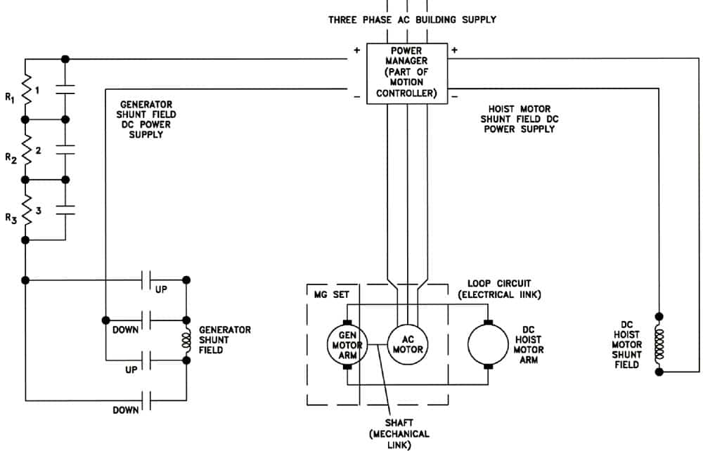
Figure 2: MG set control 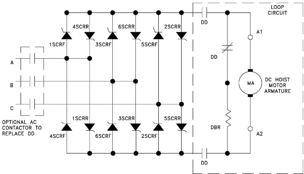
Figure 3: DC-SCR control with dynamic braking 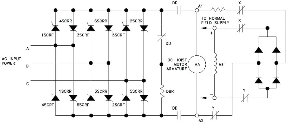
Figure 4: Dynamic braking with motor field hold-up circuit 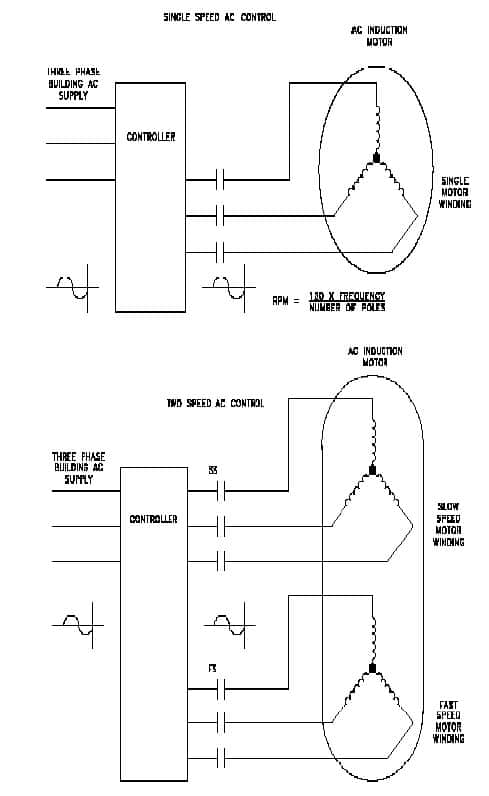
Figure 5: Single- and two-speed motor control 
Figure 6: VVAC control 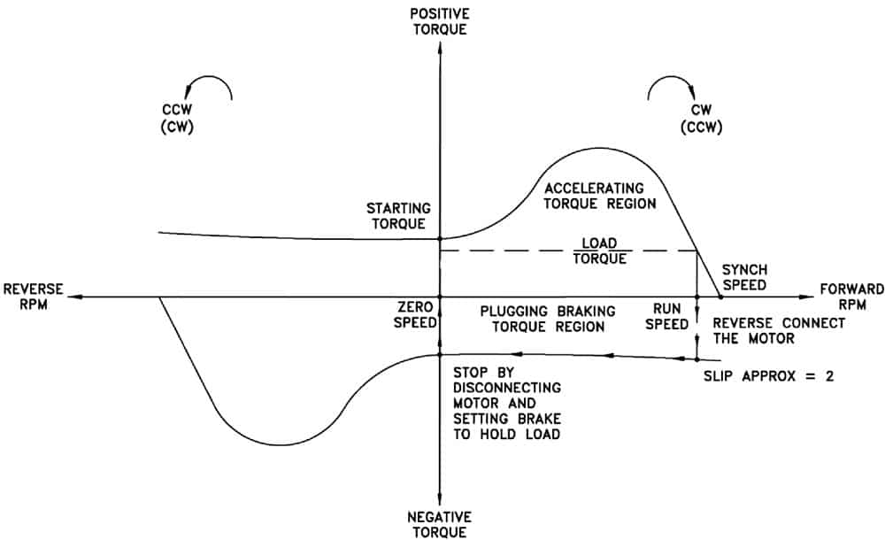
Figure 6a: Motor plugging operation 
Figure 6b: DC injection braking 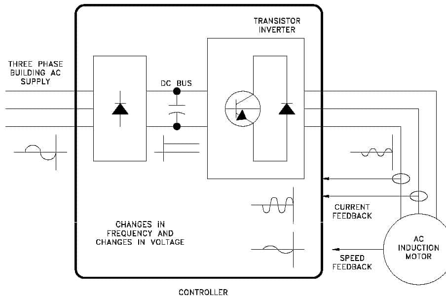
Figure 7: VVVF AC control 
Figure 8: Representative e-stop of DC motor control using dynamic braking 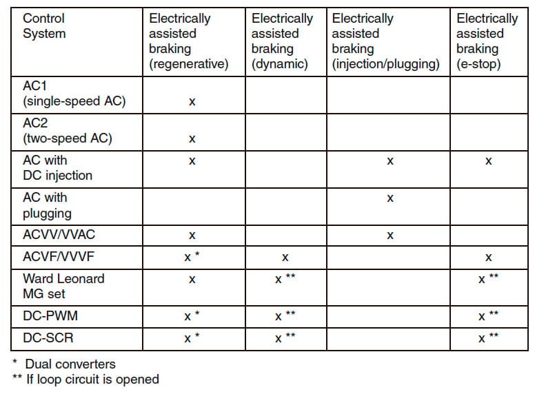
Table 1
Get more of Elevator World. Sign up for our free e-newsletter.

