In this History article, your author provides a brief presentation of early brake systems.
The first edition of Frederick A. Annett’s well-known book on electric elevators appeared in 1927. Annett devoted two chapters to brakes: one on direct-current and one on alternating-current brakes. The former included a general introduction to brake technology:
“On an elevator machine, the brake is one of the most important parts of the equipment, for upon its proper functioning depends not only the safety but also the satisfactory operation of the machine. If the brake fails to function, control of the car may be lost by the operator, with serious results. If the brake is applied too harshly, the car will be stopped with an unpleasant jerk to the passengers and the equipment will be strained unnecessarily. When the brake is not applied with sufficient force, the car will be difficult to control and make the floor landings.”[1]
Annett also noted that: “Elevator brakes have been made in about as many forms as there are types and makes of machines, so that about all that can be done in any article is to indicate a few of the different types and how they operate and are adjusted.”[1]
These introductory comments were followed by an illustrated discussion of eight direct-current brake systems. Although Annett did explicitly refer to some systems as representative of “earlier” brake types, the reader was left with the impression that the author was, primarily, discussing contemporary technologies. However, an examination of the content reveals that, when the book was published, many of these brake systems were more than 30 years old.
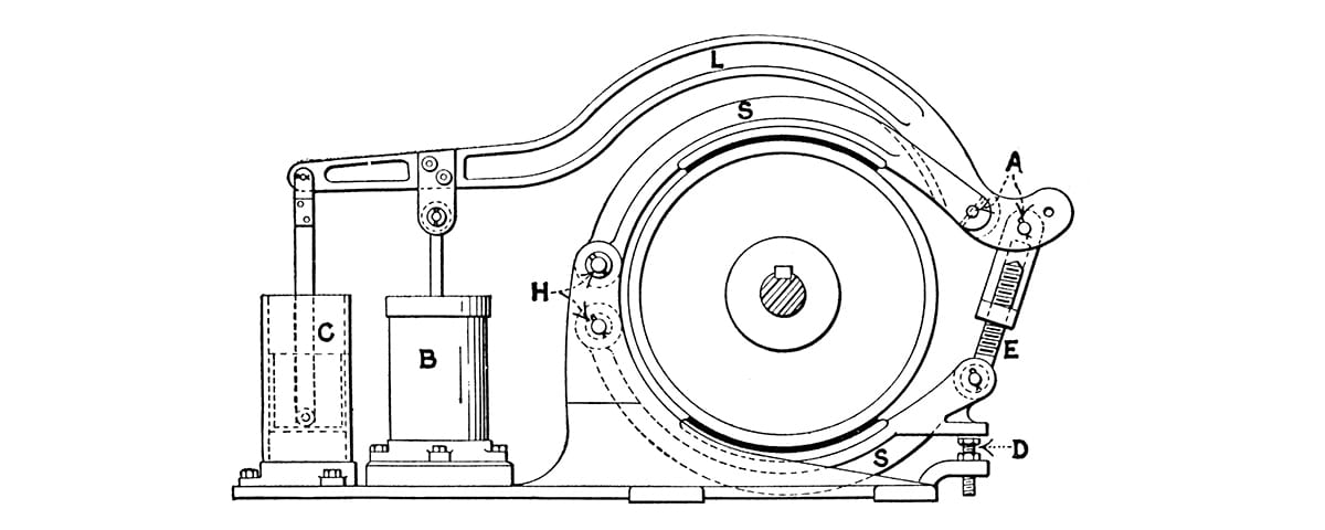
By the mid-1890s, the Elecktron Manufacturing Company had developed an electrical/mechanical brake system (Figure 1). The brake shoes were composed of two curved arms or bands that almost fully encircled the brake wheel. The original design employed cast iron bands that carried wooden brake shoes (by 1910 these had been replaced with leather shoes).
The bands were hinged on one side of the wheel and connected to the brake lever on the other side. The action of the lever was controlled by an electromagnet and an air dashpot. When the electromagnet was energized, it pushed a plunger upward that raised the brake lever and released the brakes. When power was removed, the weight of the lever caused the brakes to close. The dashpot controlled the speed of these actions and was set such that the brake was not applied too quickly, thus allowing for a smooth stop.

During this same period, Otis developed an electrical/mechanical design that also featured band-type brake shoes (Figure 2). However, with this brake, its normative use was entirely mechanical in operation, with the brake’s action controlled by a shipper wheel. The electromagnet was used as a safety device and was activated only in cases where the elevator traveled past its upper or lower limits. In this event, the electromagnet would be de-energized, which released a weight that caused the brake to engage.
The Elektron and Otis brakes, with their band-type shoes, were essentially variations on the brake system most commonly used from 1860 to 1900, which employed a continuous leather-lined band that encircled the brake wheel. However, by the end of the first decade of the 20th century, a new design had appeared that established the basic characteristics of modern brakes.
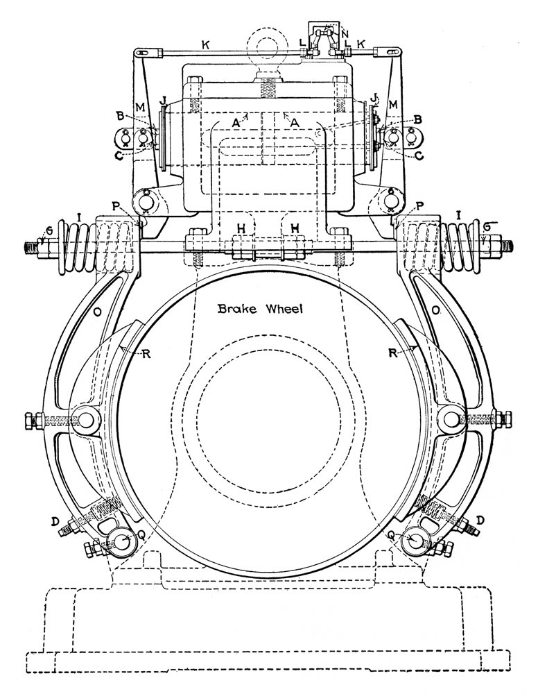
During this period, Otis developed several fully electric brake systems that employed leather-lined brake shoes mounted on either side of a central brake wheel. Each shoe was connected at its center to a brake lever whose operation was controlled by a spring mounted atop the brake. The action of the springs was controlled by a double core electromagnet. When energized, the electromagnet pulled the springs inward, which released the brakes.
On an elevator machine, the brake is one of the most important parts of the equipment, for upon its proper functioning depends not only the safety but also the satisfactory operation of the machine.
Annett noted that this design required only “a small movement of the various parts during operation.”[1] Additionally, because the brake shoes were “hinged at their middle and lifted away from the wheel at the horizontal diameter by the levers, they are lifted an equal distance from the wheel at all points.”[1] This was an improvement over band-type brakes where the shoes, when released, were often at slightly varying distances from the wheel, which occasionally caused uneven wear on the shoes.
In 1911, Otis engineer Frederick Hymans provided a detailed description of the operation of Otis’ new brake system when used on high-speed traction elevators:
“An important part of elevator machines of this type is the brake, as the very small mechanical friction of the machinery makes it necessary to rely on the brake entirely to hold the car at the landing. The brake is essentially a holding brake, that is the shoes are not applied until the machine has practically been brought to rest by dynamic braking and presents as such an interesting development. It would be undesirable to stop high speed elevator machinery of this kind by mechanical braking, on account of the large variation of the stopping distances that would result if a fixed brake pressure were applied to stop elevators having constantly changing loads. Also, the wear on such a brake would necessitate continued adjustments. The brake is held on by springs and released by a brake magnet, which is provided with a shunt winding of such proportions that its self-induction causes an appreciable lag of time between the closing of its circuit and the release of the brake shoes. Thus, while the armature and brake circuits are closed practically at the same time, sufficient time elapses to build up the full motor torque before the brake releases. When the current is shut off, there is again sufficient lag to permit the motor to come practically to a stop by dynamic brake action before the brake sets. Together with the advantage of stopping almost entirely by dynamic braking is the fact that the wear on the brake shoes is at a minimum and when once set, the brake rarely requires further adjustment.”[2]


The use of dynamic braking had, in fact, been introduced in the 1890s and was a feature of the earlier Elektron and Otis systems.
Annett illustrated two examples of Otis’ electric brakes (Figures 3 & 4). The first was described as a “brake for use on one of the earlier types of high-speed elevators” and the second was described as designed for use on a “high-speed direct-traction machine.” [1] A comparison of the latter with contemporary Otis technical manuals reveals that this was one of the few truly “modern” systems discussed by Annett (Figure 5).

This fact, along with the increasing use of high-speed traction elevators, may account for his decision to devote the final third of the chapter on direct-current brakes to this system.
Annett also used this presentation as a forum to discuss fundamental aspects of brake operation. He first described the impact on brake operation of the varying loads carried by elevators, which ranged from “the extremes of full load in up motion and full load going down.” [1] He summarized this discussion by reminding the reader that “the energy of a moving mass is proportional to its weight times the square of its velocity; therefore, the required braking action increases as the weight and the square of the speed. Twice the mass requires twice the braking action; double the speed requires four times the braking power.”[1]
Annett then described the “three distinct factors that determine the stopping of an elevator.”[1] These were identified as:
- The force of gravity, due to the unbalanced load that assists or opposes stopping.
- The motor acting as a generator when power is cut off.
- The friction of the brake shoes upon the brake pulley.[1]
Each topic was thoroughly discussed and included the appropriate formulas needed to understand their impact on brake operation.
He also provided two circuit diagrams, one that illustrated the dynamic braking system and one that illustrated the brake winding (Figure 6 & 7). The latter depicted the four resistances employed by the winding: “BR, brake resistance; ABR, auxiliary brake resistance; PBR, parallel brake resistance; (and) PBR’, auxiliary parallel brake resistance.”[1] The ABR reduced the brake winding current after the brake shoes had released. This reduced “heating in the brake magnet, at the same time providing for quick release of the brake when starting.”[1] The PBR and PBR’ resistances utilized the “energy stored up in the brake electromagnet to provide for a slow application of the brake shoes to the pulley.”[1]


This brief presentation of early brake systems, as found in Annett’s 1927 book, provides a snapshot of this technology during the first quarter of the 20th century. It also, in many ways, engages this important story somewhere “in the middle,” as the precise origins of the band- and shoe-brake systems were not discussed. Further investigation is needed to fully understand the history of brake systems, and this material will be examined in future articles.
An additional topic worthy of investigation is brake maintenance, a subject that Annett addresses in great detail, as is illustrated by the following example:
“Before a brake can be expected to work properly the surface of its linings must be in good condition. There are three common materials used to line brake shoes – namely, leather, asbestos and wood – and the preference for these materials is about in the order named. The surface of the linings should be kept free of oil and dirt. Oil may work out along the worm shaft from the gear case and get on the brake wheel. When this occurs, the shoes should be removed and the oil and dirt scraped off with glass or washed off with gasoline. Applications of Fullers earth may be made to absorb the oil, after which it can be scraped to leave the surface of the lining clean. Leather brake linings sometimes become dry and hard, in which case they should be treated with a good leather dressing or Neatsfoot oil.”[1]
This topic will also be examined in future articles, which will likely include an exploration of attitudes toward job safety, particularly in light of such guidance as the suggestion to use gasoline – in an enclosed workspace – as a cleaning agent.
References
[1] Frederick A. Annett, “Electric Elevators,” New York: McGraw-Hill Book Company (1927).
[2] Frederick Hymans, “Direct Traction Electric Elevators in the Oliver Building, Pittsburgh,” Electric Journal, (June 1911).
[3] Henry W. Ravenshaw, “Electric Elevators VI: Elektron Electric Elevators” The Electrical World (May 8, 1897).
[4] Henry W. Ravenshaw, “Electric Elevators VII: Otis Electric Elevators” The Electrical World (May 22, 1897).
[5] Elevators, International Textbook Company, New York (1902).
[6] William Baxter, Jr., “Electric Elevators,” Power (January 11, 1910).
[7] William Baxter, Jr., “The Electric Elevator: Elektron System with Mechanical Control,” Power (July 5, 1910).
Get more of Elevator World. Sign up for our free e-newsletter.


