Elevator Door Force
Nov 1, 2015

Maladjustment of elevator door controllers can cause injury to persons if impacted by a closing door with a high speed. Persons can also be entrapped or crushed by a door system with too much door closing force. Education and vigilance when performing elevator door adjustment and maintenance is critical for safety. Door-related incidents are estimated to exceed 40% of all elevator-related injuries. Other types of injuries include 40% related to trip and falls, where the elevator is not level. This means 80% of all injuries occur at the entrance. With the high incidence of door-related injuries occurring, it is clear that more education to ensure doors are code compliant is warranted, along with, perhaps, a reexamination of code values of pressure and force.
Design Requirements
ASME A17.1/CSA B44 code requirements call for elevator-door closing forces and kinetic energy to be limited to prevent high-energy impacts to a person when struck by a closing door. There are also requirements to limit crushing forces in the closing movement between the door panels and door strike with a person in the entrance. This generally, but not always, is the center third of travel, given the width of a person. Limiting these forces and energy levels requires an understanding of code requirements and door-operator adjustments.
There are sometimes competing interests to increase the door closing speed to improve elevator performance and lower the frequency of maintenance, but this is at the expense of increasing door-impact incidents. Before they make adjustments and repairs, mechanics must know the importance and impact the work can potentially have on users of the elevator.
Elevator door operators have a means by which to adjust the door force to below 135 N (30 lbf). (A Newton [N] is the force needed to accelerate 1 kg at the rate of 1 mps2; a pound force [lbf] is the force needed to accelerate 1 avoirdupois pound [lbm] at the rate of standard gravity [g].) Door operators also have a means by which to adjust door speeds to ensure the kinetic energies are kept at or below 23 J (17 ft.-lbf) at any point in the code zone (instantaneous) and 10 J (7.37 ft.-lbf) where a reopening device is used. Where a door-reopening device is not used, these kinetic energies must be kept below 8 J (6 ft.-lbf) at any point in the code zone (instantaneous) and 3.5 J (2.5 ft.-lbf). (A Joule [J] is energy equal to the work done when applying 1 N through a displacement of 1 m. A foot-pound of force [ft.-lbf] is equal to the work done when applying a force of one pound-force [lbf] through a displacement of 1 ft.)
This means there are three measurements and adjustments that must be made on door operators. This is the most overlooked concept contributing to hazardous door movement. The door force of 135 N (30 lbf) is easiest to ensure, because there are simple tools available to measure the force (figures 1 and 2). The kinetic energies are often considered somewhat of a mystery (due to being difficult to measure) and are, therefore, the most often overlooked. This article will demystify the enigma of adjusting kinetic energies.
Changes in Door Closing Speed and Force
When a new elevator is adjusted and has to pass an acceptance inspection with the AHJ, the tests include the door force test and kinetic-energy verification based on door closing time. If the doors are binding when first inspected, it is likely that the door speed and force will increase as the doors wear in. This must be measured and corrected as soon as the energies and forces appear to be above code levels.
Door speeds and, particularly, door forces will change as the frictional components of the system change. Some components may wear in, while others wear out and have to be replaced. Replacement parts can affect the forces if the parts are not exactly the same brand or quality. The accumulation of dirt and debris (particularly construction dust) over time will have an effect. Doors impacted by carts may be bent, causing misalignment and considerable friction.
Modern-day door operators have separate adjustments for closing speeds and closing force. As long as the closing force is set to compensate for various frictional forces, the closing speeds will be the same at all floors. If the force is adjusted at a floor that has higher friction, it must be checked at the floor that has the least friction, because this floor will have the greatest force.
It is these changes in energies and forces for which code verification is required in A17.1/B44 Section 8.6 and for which the means to test is provided in the maintenance control program. Testing should be done as often as an analysis of the job conditions require: according to this section, either annually or as often as every visit. Section 8.6 requires this analysis to ensure the frequency of testing and maintenance is adequate to keep the forces in compliance.
Carrying the necessary force gauge to spot check every door on every visit is not hard or burdensome; it takes approximately 30 s. and will lead to more compliant, safer doors. Timing the door close times and comparing them to the minimum times listed on the door data plate can be done within this timeframe, as well. These tasks are necessary to ensure the doors’ closing times have not changed to noncompliant levels.
Understanding Code
The requirements for these forces are found in A17.1/B44 Part 2, Requirement 2.13.4.
Door Closing Force
The following is directly from ASME A17.1-2013/CSA B44-13:
- “2.13.4 Closing Limitations for Power-Operated Horizontally Sliding Hoistway Doors and Horizontally Sliding Car Doors or Gates “2.13.4.1 Where Required. Where a power-operated horizontally sliding hoistway door or car door/gate or both is closed by momentary pressure or by automatic means (see 2.13.3.3), or is closed simultaneously with another door or car door/gate or both from one continuous-pressure means (see 2.13.3.2.3 and 2.13.3.2.4), the closing mechanism shall be designed and installed to conform to 2.13.4.2 and the reopening device shall be designed and installed to conform to 2.13.5.
- “2.13.4.2 Closing Mechanism. . . 2.13.4.2.3 Door Force. The force necessary to prevent closing of the hoistway door (or the car door or gate if power operated) from rest shall not exceed 135 N (30 lbf) (see 2.13.3.1). This force shall be measured on the leading edge of the door with the door at any point between one-third and two-thirds of its travel.”
Measurement of Door Force Using a Door Force Gauge
Two common tools in use are shown in figures 1 and 2. Both gauges use a spring of a known spring rate with a calibrated scale indicating the applied force. Both gauges are applied to the closing door when the doors are in the center third of door panel travel, stalling them with the gauge, just allowing door movement, then reading the force.
This procedure is described in the ASME A17.2 Guide for Inspection of Elevators, Escalators and Moving Walks, Item 1.8.1:
“ASME A17.2-2014
“ITEM 1.8
“DOOR CLOSING FORCE
“1.8.1 Periodic Inspections To test the door closing force, park the car at floor level and start the doors in the closing direction. Allow the doors to close between one-third and two-thirds of their normal travel and stop them. Push a force-measuring device with a range appropriate to measure 30 lbf (133 N) against the stopped door, removing the stop so the door is held stationary by the force-measuring device. Slowly back off on the device until the point the door just starts to move. At this point, the door and measuring forces are in equilibrium and the force can be read. . . .
“ITEM 6.5
“ACCEPTANCE CHECKLIST FOR FIREFIGHTERS’ SERVICE (ASME A17.1–2000 and CSA B44-00): AUTOMATIC ELEVATORS. . .
“6.5.6 Phase I Operation With Doors Open Place the Phase I switch to the “OFF” position and run the car to any floor. With the doors open, have the Phase I switch turned to the “ON” position and check the following:
. . .
(b) If door reopening devices are rendered inoperative, the closing speed is reduced so that the kinetic energy is reduced to 2 ½ ft-lb (3.5 J). . . .”
Most testing and inspection procedures are found in ASME A17.2, which indicates how the AHJ will generally perform inspections. Technicians should use it (the book the inspectors use) to ensure a job is in compliance. It lists 133 N (30 lbf) where the code lists 135 N (30 lbf), but this is just a difference from metric rounding practice between publications. Either is valid.
If the measurement indicates too much force, in excess of the 135 N (30 lbf), the door operator needs to be adjusted. The limiting of electrical power applied to a door motor solely controls door force (torque). When there is more current to the motor armature, there is more available closing force and vice versa. Figures 4 and 5 depict typical door-operator circuits from two common operators: one rheostatic (using resistors) and one solid-state (using electronic controls). Figures 6 and 7 indicate where the physical adjustments are made in the circuit. These drawings are for illustration purposes only; always consult the OEM manual before adjusting an in-service elevator door operator.
These adjustments may be on the door operator; in the elevator controller; or, in some cases, adjusted with a handheld tool standing in the car. You must familiarize yourself with the specific door operator, but the general designs are similar, and the results are the same.
While the code limit is a maximum of 135 N (30 lbf) of closing force, there is no reason to adjust it higher than necessary. Adjust this to the very minimum to obtain reliable operation. The lower the current, the less the crushing force. Common injuries result from the door reopening device being unobstructed and a person being pinned between the hoistway doors and the door strike or jamb, or between the center-opening hoistway doors. In many cases, the force can be set between 60 and 80 N (13 and 18 lbf). There is no reason to set this to the maximum.
When properly set, increasing the torque (current limit) will not increase the speed. Decreasing the torque will only decrease the door speed when there is not enough power to reach that speed. Do not adjust the current limit if attempting to change the kinetic energy. This is analogous to increasing the relief pressure on a hydraulic elevator valve and expecting an increase in car speed.
Kinetic Energy
Kinetic energy is the energy of motion. Recall that all objects with mass are subject to forces. The following is a physics refresher. A book resting on a table has potential energy; the force due to the acceleration of gravity is pulling the book down as the table resists the force, holding it up. If the book were slid off the table and allowed to fall to the floor, its potential energy is converted to kinetic energy until it hits the floor. Just as the falling book accumulated kinetic energy, so will closing elevator doors.
The farther the book falls due to the acceleration of gravity at 9.8 mps2 (32.2 fps2), the higher its velocity, until the floor stops it. This increase in kinetic energy is shown in the kinetic-energy formula (Equation 1). The velocity increases relative to the distance it is in motion. The kinetic energy increases with the square of the velocity.

where:
EK = kinetic energy
m = mass
v = velocity
In elevator-door terms, the door operator moves the doors with a closing velocity that accelerates the mass to full speed, then decelerates toward zero speed until fully closed. All door operators have adjustments to raise or lower the velocity, which, in turn, raises or lowers the kinetic energy. (In this article, velocity and speed have been used synonymously up to now, but there is a difference. Velocity is a vector quantity, which has both magnitude and direction, while speed is a scalar quantity that only has magnitude. Since we are speaking of velocity in one vector direction and there are no other vectors to consider, speed is also correct to use in this case.) To know what the kinetic energies of a moving door system are, we need to know the total mass and average velocity. Often, mechanics don’t know the mass of older doors and can only use a timer to measure the closing doors to get the average velocity, so it seems we are always in an unknown condition. Hence, many door-strike incidents causing injury are due to high kinetic energies.
Further Reading
George W. Gibson’s articles “Kinetic Energy of Passenger Elevator Door Systems”[1] and “Instantaneous Maximum Kinetic Energy of Horizontally Sliding Passenger Elevator Door Systems”[2] detail more in-depth mathematics for readers interested in a treatise of door kinematics and mathematics. Even further education on this topic can be found in Systems Engineering of Elevators by Phil Andrew and Dr. Stefan Kaczmarczyk.[3] For a practical perspective from a design engineer, Elevator Engineering by Ben Abbaspour[4] is a useful book. I also recommend the resources of Bob Desnoyers, who runs a website with many utilities, such as his “Minimum Door Time Calculator,” at elevatorbob.com.
In this article, the goal is to explain the problem and solutions in simpler, hands-on terms for mechanics with basic principles and simplified examples. Certainly, more detailed formulae are required when designing equipment and for creating code. This article is to explain the principles for mechanic and technician education and, hopefully, prevent hazardous doors as much as possible.
Code
The requirements in code for kinetic energies are found in requirement 2.13.4:
“ASME A17.1-2013/CSA B44-13
“2.13.4 Closing Limitations for Power-Operated Horizontally Sliding Hoistway Doors and Horizontally Sliding Car Doors or Gates
“2.13.4.1 Where Required. Where a power-operated horizontally sliding hoistway door or car door/gate or both is closed by momentary pressure or by automatic means (see 2.13.3.3), or is closed simultaneously with another door or car door/gate or both from one continuous-pressure means (see 2.13.3.2.3 and 2.13.3.2.4), the closing mechanism shall be designed and installed to conform to 2.13.4.2 and the reopening device shall be designed and installed to conform to 2.13.5.
“2.13.4.2 Closing Mechanism
“2.13.4.2.1 Kinetic Energy
(a) Where the hoistway door and the car door/gate are closed in such a manner that stopping either one manually will stop both, the kinetic energy of the closing door system shall be based upon the sum of the hoistway and the car door weights, as well as all parts rigidly connected thereto, including the rotational inertia effects of the door operator and the connecting transmission to the door panels.
(b) Where a reopening device conforming to 2.13.5 is used, the closing door system shall conform to the following requirements:
(1) The kinetic energy computed for the actual closing speed at any point in the Code zone distance defined by 2.13.4.2.2 shall not exceed 23 J (17 ft.-lbf).
(2) The kinetic energy computed for the average closing speed as determined in accordance with 2.13.4.2.2 shall not exceed 10 J (7.37 ft.-lbf).
(c) Where a reopening device is not used, or has been rendered inoperative (see 2.13.5), the closing door system shall conform to the following requirements:
(1) The kinetic energy computed for the actual closing speed at any point in the Code zone distance defined by 2.13.4.2.2 shall not exceed 8 J (6 ft.-lbf).
(2) The kinetic energy computed for the average closing speed within the Code zone distance (see 2.13.4.2.2), or in any exposed opening width, including the last increment of door travel, shall not exceed 3.5 J (2.5 ft.-lbf).
“2.13.4.2.2 Door Travel in the Code Zone Distance
(a) For all side sliding doors using single or multiple speed panels, the Code zone distance shall be taken as the horizontal distance from a point 50 mm (2 in.) away from the open jamb to a point 50 mm (2 in.) away from the opposite jamb.
(b) For all center-opening sliding doors using single or multiple-speed panels, the Code zone distance shall be taken as the horizontal distance from a point 25 mm (1 in.) away from the open jamb to a point 25 mm (1 in.) from the center meeting point of the doors.
(c) The average closing speed shall be determined by measuring the time required for the leading edge of the door to travel the Code zone distance.”
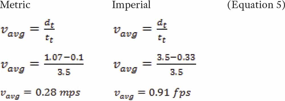
The code references both kinetic energy (EK) “at any point” and the kinetic energy computed for the “average closing speed.” The use of the word “any” includes the maximum or peak EKpk or EK at the highest velocity the door panel travels. For simplicity, we will use the term “Average EK” based on the average velocity (average closing speed): the total distance the panel travels divided by the total time taken. All we need to know is where to start a timer and where to stop it. This is the “code zone” described in requirement 2.13.4.2.2 and is the total movement of a side-opening door panel minus 100 mm (4 in.). So, for a side-opening panel, you do not count the first 50 mm (2 in.) or last 50 mm (2 in.) of travel. For a center-opening door, the code zone distance is half the door opening minus 50 mm (2 in.) starting at 25 mm (1 in.) away from the open jamb to a point 25 mm (1 in.) from the center meeting point of the doors. The average velocity is calculated by dividing the total code distance by the total time.

where:
vavg = average velocity
dt = total distance traveled
tt = total time
The velocity is very slow at the extreme end of door travel, so the EK is very low; therefore, the code excludes the first and last side-opening bit of door panel’s travel when calculating the average door panel velocity for EK determination. Also, there is simply no room to get much in there to be impacted.
Example
To assist in learning about kinetic energy, let’s start with an example of the familiar. Imagine a book sitting on a table. If the book is pushed off the table, it falls to the floor. To calculate peak kinetic energy (EKpk) of the falling book, the peak velocity of the book must be calculated. The formula to find peak velocity of a falling book (vpk) is the square root of twice the acceleration times the distance moved (Equation 3). Given gravity (g) = 9.8 mps2 (32.2 fps2) and height (h) = 1 m (3.28 ft):
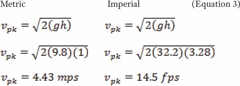
where:
vpk = peak velocity
g = acceleration of gravity
h = height
Determining the EKpk of closing elevator doors can’t be directly measured without special tools, but is easily calculated. If we know the mass and peak velocity at a point, we can know the EKpk value at that point. This is similar to knowing the mass and peak velocity as the book hits the floor. If we use a tachometer set to feet per second to measure the closing door’s velocity, we can record the peak velocity that would also represent where the EKpk is located in the door path.
With the peak velocity known, the EKpk formula can be solved when you know the mass of the object. Calculating the EKpk of the falling book from above, given mB = 0.91 kg (2 lb. = 0.06 slug) and vBpk = 4.43 mps (14.5 fps):
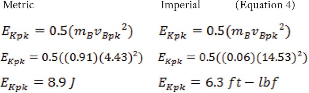
where:
EKpk = peak kinetic energy
mB = mass of book
VBpk = velocity of book
J = Joules
“Slug” is not a commonly used term in the field, but it should be. A slug is the imperial unit of mass. It is its weight (lbf) divided by the standard gravitational acceleration. So, if an object weighs 32.17 lbf, its mass is 1 slug (32.17 lbf/32.17 fps2 = 1 slug). In the International Space Station, the same object would still have a mass of 1 slug, but its weight would be zero, because it is beyond the reach of the acceleration of gravity. In the imperial system we have interchanged “lb” and “lbf” for so long, many think they are the same. To use the imperial energy formula, the correct units must be used, and the slug is the correct unit. (This problem does not exist in the metric system, as mass is measured in kilograms, and weight (force) is measured in Newtons.)
So, we were able to calculate the EKpk of the book because we knew its mass and velocity. For elevator doors, we need to know the mass of the door panels and all the connecting equipment, and the equivalent mass due to the rotational inertias (flywheel effects of the rotating motor armatures and pulleys) in order to know what EKpk is and adjust to the door closing speed for code compliance. For this example, assume the total door mass is 180 kg (396 lb. = 12.3 slugs). The velocity also needs to be known.
Average velocity is simply the total distance traveled divided by the total time taken. For elevators, we don’t use the entire opening; we subtract 0.1 m (4 in.) per entrance width. In a 1.07-m (42-in. or 3.5-ft.) side-opening entrance, if the side-opening door panel takes 3.5 s., the velocity is:
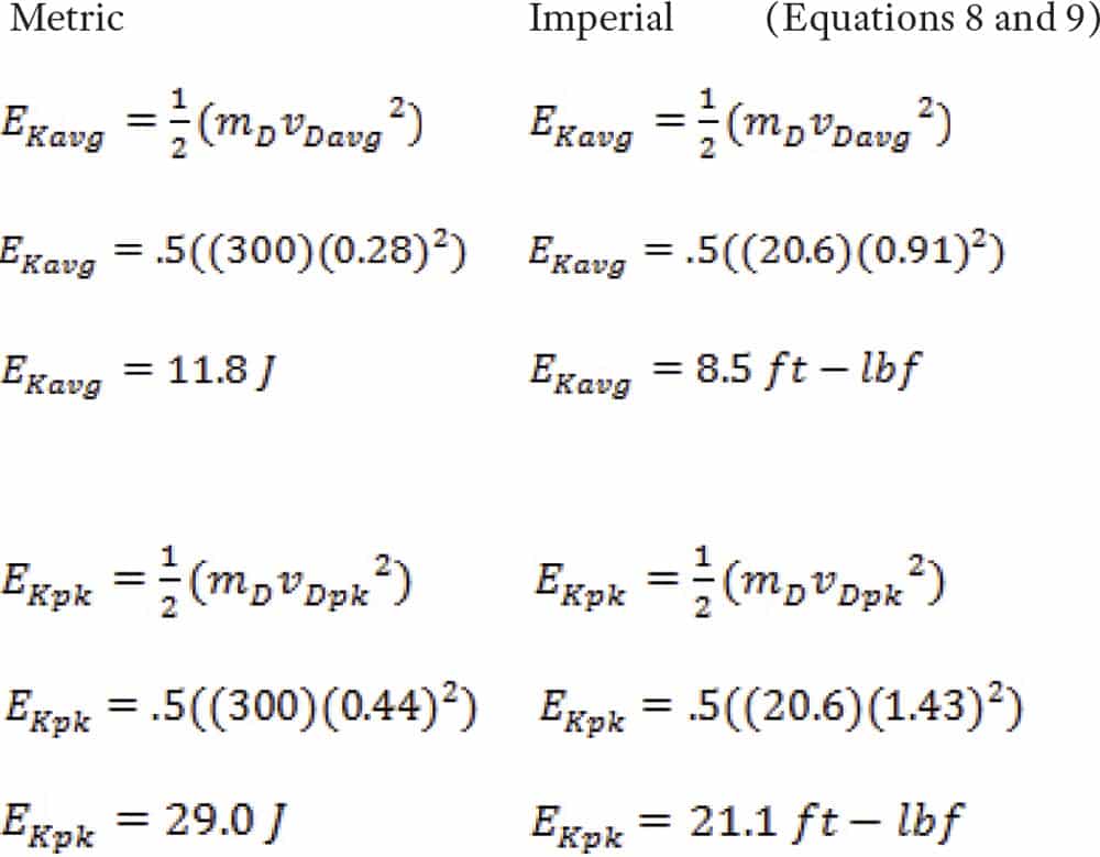
With a harmonic door operator, one with a sinusoidal motion, the relationship between maximum speed and the average speed is a ratio of approximately 1.57:1,[2] meaning that, if the average velocity is known, multiply by 1.57 to find the approximate peak velocity. If a tachometer measured the highest door-panel velocity, on a harmonic door operator with an average velocity of 0.28 mps (0.91 fps) as above, it would be 0.44 mps (1.43 fps). Plug these velocities into the kinetic-energy formulae to get the average EKavg (Equation 5), then the EKpk (Equation 6), given mD = 180 kg (396 lb. or 12.3 slug) and vDavg = 0.28 mps (0.91 fps):
where:
mD = total mass of doors
vDavg = average velocity of door panel
vDpk = peak velocity of door panel
Ekavg = average kinetic energy
EKpk = peak kinetic energy
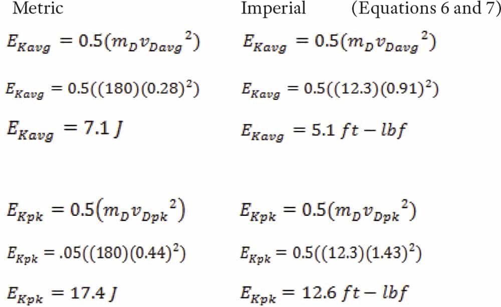
Recall the code limits: Ekavg cannot exceed 10 J (7.37 ft.-lbf), and EKpk cannot exceed 23 J (17 ft.-lbf). The values in equations 6 and 7 comply with the code.
It should become clear that, if the doors were heavier, 300 kg (662 lb. or 20.6 slugs) and moved at the same velocity as in equations 6 and 7, then, logically, the kinetic energy would increase. So, given mD = 300 kg (662 lb. = 20.6 slug) and vDavg = 0.28 mps (0.91 fps):
The values now exceed the kinetic-energy code maximum, though the doors closed at the same velocity.
29 J (21.1 ft.-lbf) is the approximate energy used in lifting 11 kg (25 lb.) 1 ft. Said another way, it is equivalent in kinetic energy to 11 kg (25 lb.) dropped from 1 ft. The door panel is moving horizontally, but this is only at its maximum speed. Recall that the door speed changes with a harmonic operator, but the linear type can be programmed to be full speed throughout the travel or simulate the harmonic sinusoidal changes. Persons using the elevator are exposed to these impacts.
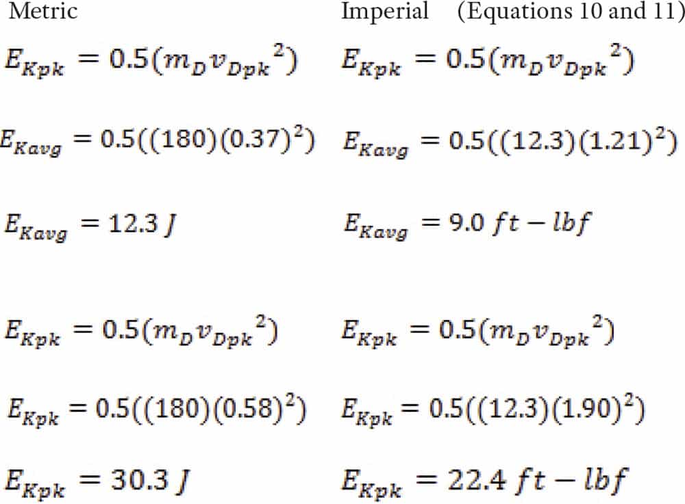
Since door weights typically do not change (but door velocity does), let’s reduce the door closing time by arbitrarily increasing the closing velocity, changing the average velocity to 0.37 mps (1.21 fps). If a tachometer measured the highest door-panel velocity, it would be approximately 0.58 mps (1.90 fps) (the average velocity times 1.57) for a harmonic door operator.
An increase in door-panel velocity increases the energies to above code limits. Well-intentioned increases in door speeds, without considering these effects, may solve service problems but create new hazards that injure persons impacted by the doors. This explains the significance of seemingly small velocity increases that may create hazardous unintended consequences.
Harmonic Versus Linear Door Operators
So far, we have dealt with harmonic door operators producing a sinusoidal motion, motion around a circle as the pulley rotates the drive arm. Given that the motor turns at the same speed, the drive arm increases in speed as the pulley rotates, then decreases in speed to zero at the end of door travel. Therefore, the peak velocity is 1.57 times the average velocity. This is generally true enough that, by simply measuring the average velocity, the peak can be closely estimated. In code, the addition of instantaneous kinetic-energy values is the result of this factor.
With a linear door operator, the door speed is directly proportional to the motor speed, where the speed curve is more of a trapezoidal waveform. Most of the cycle takes place during acceleration and deceleration. With a harmonic-motion door operator, the motor speed remains somewhat constant, but the speed of the door changes during the acceleration and deceleration cycle, producing a sinusoidal motion. The peak velocity with harmonic motion is approximately 1.57 times the average velocity, and the peak velocity of a linear door operator is 1.52 times the average.[2] Both produce a peak kinetic energy of 17 ft. lb.
Now we should understand the significance of making speed changes in the door system. The ultimate problem is that on older elevators, the door masses are unknown. Here is where the code works for you.
Code Solution
To determine the weight of the doors, one would theoretically need a tachometer and force gauge, and take a force reading where the average velocity intersects the actual velocity of the door panel of a harmonic door operator because of the constant rate of velocity change due to the rotation of the pulley. Similarly, with a linear door operator, a measurement in the constant velocity area of motion with a force gauge could be used to measure the force and, perhaps, be used to determine the mass of the doors.
These methods could measure the total force and actual acceleration during retardation to calculate mass, mass being equal to force divided by acceleration (m = F/a); a rearrangement of the F = ma fundamental equation. You also could literally take the doors off the tracks and weigh them on a scale, but the rotational inertias would still be a mystery.
All these methods are time consuming, extremely expensive and leave room for error. For example, there is no way to measure the rotational inertias, except through direct force-gauge measurement of the closing door system and subtracting the non-rotational door masses or detailed calculations. No tools have been designed for this function. So, how do we find the mass and, therefore, know if the doors are adjusted correctly?
Manufacturers know the total masses of their door systems, and, since the 2000 edition of code, a door data plate is required to be provided with minimum door closing times. This data plate should be on all new elevators and all elevators that have had alterations to their door operators:
“ASME A17.1-2000/CSA B44-00
“2.13.4.2.4 Data Plate. A data plate conforming to 2.16.3.3 shall be attached to the power door operator or to the car crosshead and shall contain the following information:
(a) minimum door closing time in seconds for the doors to travel the Code zone distance as specified in 2.13.4.2.2 corresponding to the kinetic energy limits specified in 2.13.4.2.1(b)(2)
(b) minimum door closing time in seconds for the doors to travel the Code zone distance as specified in 2.13.4.2.2 corresponding to the kinetic energy limits specified in 2.13.4.2.1(c)(2), if applicable [see 2.27.3.1.6(e)]
(c) where heavier hoistway doors are used at certain floors, the minimum door closing time in seconds corresponding to the kinetic energy limits specified in 2.13.4.2.1(b)(2) and 2.13.4.2.1(c)(2), if applicable, for the corresponding floors shall be included on the data plate”
The plate provides the minimum door closing times. Now, all the mechanic needs is to time the door closing time in the code zone and determine whether it is too fast. There will be no need to weigh the mass.
In addition to the code data plate, the 2016 edition of the code has a non-mandatory appendix with some minimum door times for standard door types and openings. These door closing times are based on door weights provided by some Canadian door manufacturers. While this is a good step, knowing the exact kinetic energy is the ideal, and until a practical method to calculate the weight of the doors is made affordable, we can only ask the manufacturers how much panels weigh, take off the door panels and weigh them, or estimate the weight and err on the conservative side. This table is only an estimate of weights, but it errs on the heavy (safer) side:
“ASME A17.1-2016/CSA B44-16 Non-Mandatory Appendix
“NOTES:
(1) This Table was developed to assist in annual maintenance inspection in accordance with 8.6 requirements where no data plate is provided in accordance with 2.13.4.2.4
(2) The data provided in the Table are based on a survey of several Canadian manufacturers based on information data in the early 1990’s and are intended to be used as a guideline only.
(3) The Table covers sheet steel doors with painted surfaces without cladding.
(4) Door closing time, t, expressed in the table as either normal speed or reduced speed is the time to travel from a point 50 mm (2 in.) away from jamb to a point 50 mm (2 in.) away from the opposite jamb for side opening doors. In the case of center opening doors, time to travel is from a point 25 mm (1 in.) away from jamb to a point 25 mm (1 in.) from the center. This distance is referred to as the code zone distance in A17/B44 Requirement 2.13.4.2.2.
(5) In the absence of actual minimum door close time from the manufacturer, use the upper time limit of the range for adjustment and inspection purposes.”
Consultants often cite specific door close times for various entrance widths. This “industry standard” is typically based on door weights of 3.62 kg/m2 (8 lb./ft.2). If the doors are clad with decorative cladding, the weight can be increased as much as 0.9 kg/m2 (2 lb./ft2), and, therefore, door close times must be increased for the extra kinetic energies. Today, doors are much lighter, and the door data plate covers the modern doors. There are still many older doors without a door data plate, typically of the heavier variety.
To determine the weight of a side-opening hoistway door, determine the area of the door panel. Table 1 summarizes common weights for steel doors.
The hoistway door and car door masses need to be added to determine the total mass. The car door could be taller, typically is not wider, and could be cladded or uncladded. Once you establish its type, sum all the door panel weights. Finally, adding 20% for rotational inertias and door-mounted accessories will give the effective mass.
Example
Calculate the effective mass for a 2.743-m (9-ft.) -tall door opening with a 1,066-m (42-in.) -wide entrance. Remember that the doors overlap the actual entrance opening on the top and sides by approximately 13 mm (0.5 in.), so the total size of the door panels is 2.756 m X 1.092 m (109 in. X 43 in.)
The lobby doors are heavier because of the cladding; the upper floors are lighter, because they are uncladded. For the rotating masses and accessories, we will simply add 20% of the door-panel mass to be conservative.
The effective weight of the lobby door system is 316 kg (696 lb.). The door close time of 3.9 s. is calculated at the maximum allowable kinetic energy of 10 J (7.37 ft.-lbf). The effective weight of the upper-floor door system is 281 kg (619 lb.). This would give a minimum door time of 3.6 s. at the maximum allowable kinetic energy of 10 J (7.37 ft.-lbf).
The significance of this is that using the speed used on the lighter upper-floor doors for the heavier lobby door will exceed the kinetic energy limit. This is why many door operators have a separate heavy-door setting that must be adjusted, in addition to the rest of the doors.
There are two components needed to evaluate the EKavg of a door system. The first step is timing the doors in the code zone to determine the average velocity. One could also use a tachometer, record the peak velocity and divide by 1.57 for a harmonic door operator for a ballpark average velocity, but timing the doors in the code zone is easiest. The second step is calculating the effective mass.
There is one more factor to complete this example. Doors come in single-, two- and three-speed vareities. The masses are seperated by some relating mechanism that is not solid. Therefore, a reduction factor is used. This is Q in Equation 13.[2] If the doors are single speed, Q = 1; if two-speed, Q = 0.625; and if three-speed, Q = 0.222.
Example
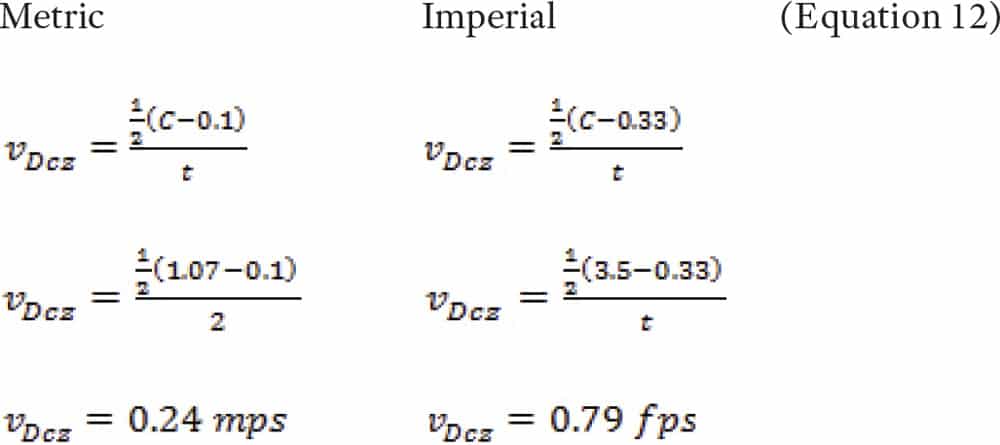
Determine the kinetic energy of an elevator-door system with a 2.13-m (7-ft.) single-speed center-opening door with a clear opening of 1.07 m (3.5 ft.), total door weight of 256 kg (563 lb. = 17.5 slugs) and measured door closing time of 2 s. with an operative door-reopening device.
First determine the door panel velocity in the code zone:
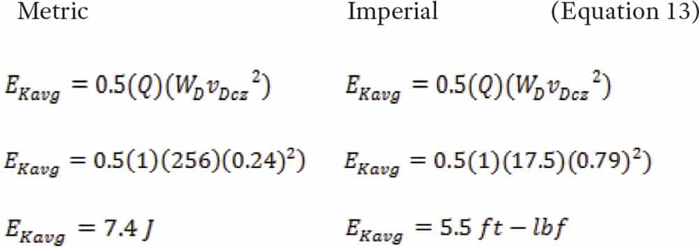
Then, use velocity in the code zone (vDcz) to complete the calculation:
The result is less than 10 J (7.37 ft.-lbf), the maximum EKavg with an operational reopening device required by the code. Therefore, it is code compliant.
Summary
There is not a need to be at a maximum force and energy in most cases. The need for speed at a convalescent hospital is not as critical as at a class-A office building. Consider the users, adjust the speeds as appropriate and eliminate the high rate of injurious incidents.
The code also speaks about reduced energy when the door-reopening device is rendered inoperative or is not present. This is typically called “nudging operation”: simply stated, the doors must go much slower to have a reduced kinetic energy. This speed will simply nudge someone out of the plane of travel so the elevator can still operate. All that changes is the door speed and, therefore, the door closing times. One would use the same formulae for calculating nudging times to limit the kinetic-energy values.
When people are struck by the doors, they are rarely hit by the average kinetic energy. Incidents most often take place when the door is at its center third of travel, where its kinetic energy is likely higher than average. This may indicate a reduction in these energies might be appropriate in buildings and facilities where older persons work and live. This population moves slower and is impacted by the hoistway doors not reaching the reopening device mounted on the car door. This is, perhaps, a subject for another article, but a change in the code might be warranted.
More education to ensure doors are code compliant is warranted, along with, perhaps, a reexamination of code values of pressure and force.
Code writing utilizes incident history and hazard assessment based on predictable human events, foreseeable misuse and common sense when specifying the maximum kinetic energies doors can have. This is squarely juxtaposed against wanting the fastest door times, to have the fastest floor-to-floor times and, therefore, maximum elevator performance for the building. However, there are speed limits on roads and highways for similar reasons: excessive speeds have shown to be hazardous; therefore, we impose limits to reduce these hazards.
There will be people who are struck by doors for many reasons: running to catch the elevator, standing where the reopening devices cannot detect their presence in the plane of the hoistway doors and not paying attention. Limiting the kinetic energies is our way to ensure that the majority of these impacts are simply a nuisance, not damaging incidents. Mechanics are the final adjusters every day. It is our responsibility to know what the code requires and to adjust the elevator to code. We should:
- Regularly verify the door force with a force gauge
- Regularly verify the door close time with a stopwatch
- Know the limits of adjustment when changing the door speeds
- Record all related values for easy permanent retrieval, preferably on a door data plate
Accordingly, elevator companies should:
- Train mechanics to understand the importance of door hazards
- Provide the tools and training to each route mechanic
- Ensure that proper recording of these values is in the maintenance records
- Add a door data plate to every door operator
Acknowledgements
Peer reviewed by: Louis Bialy, Consultant; and Walter Glaser, G.A.L. Manufacturing – Members of the Elevator World Technical Advisory Group.
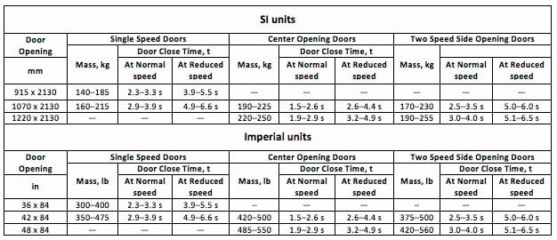
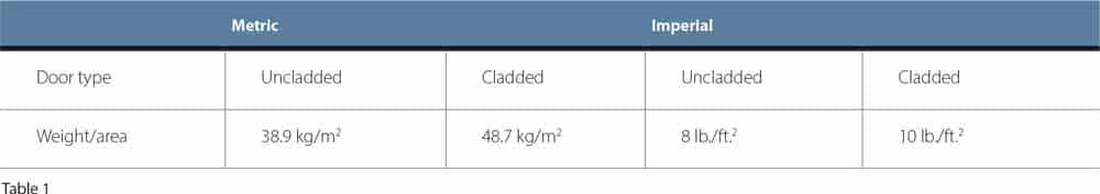
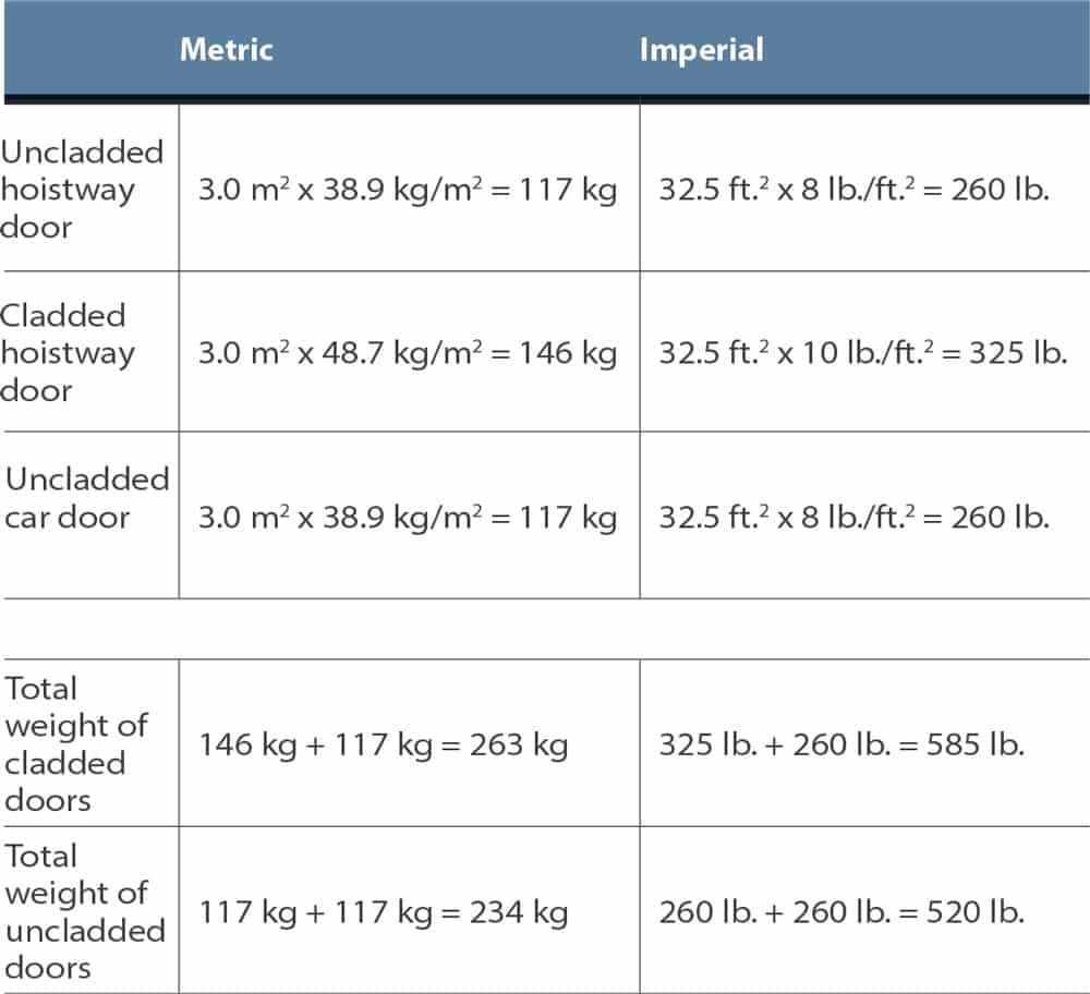


Figure 1: Door force gauge 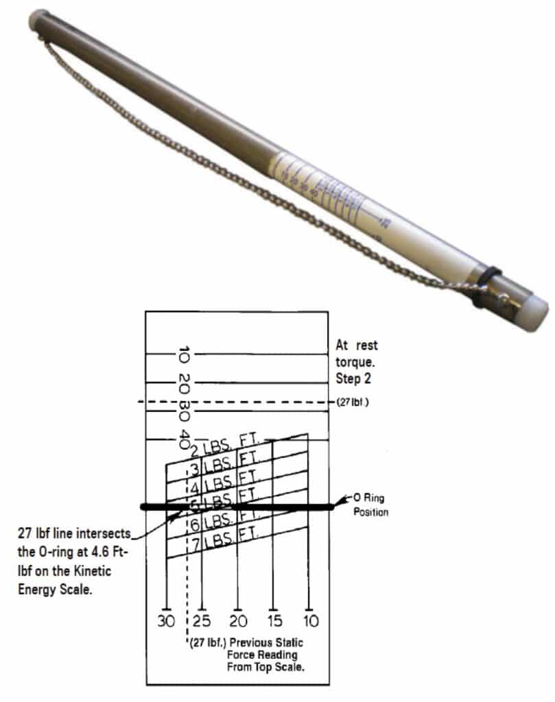
Figure 2: Door force gauge (courtesy of ThyssenKrupp) Figure 3: Center third of travel (highlighted) to measure door force 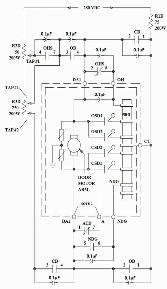
Figure 4: Typical rheostatic door-operator control wiring diagram (courtesy of ThyssenKrupp) 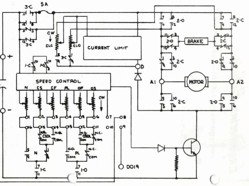
Figure 5: Typical solid-state door-operator control wiring diagram (courtesy of KONE) 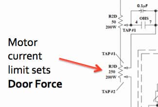
Figure 6: Typical sliding resistor tap adjustment: increased resistance decreases current to the door motor and, therefore, the force. 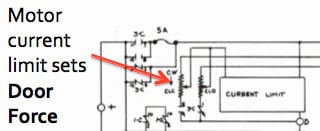
Figure 7: Typical electronic symbol for a variable resistor: it uses a small-tipped screwdriver. 
Figure 8: Code zone 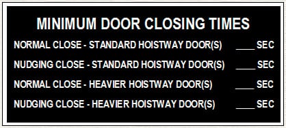
Figure 9: A typical door data plate

References
[1] Gibson, George W. “Kinetic Energy of Passenger Elevator Door Systems” ELEVATOR WORLD, December 1989 and January 1990.
[2] Gibson, George W. “Instantaneous Maximum Kinetic Energy of Horizontally Sliding Passenger Elevator Door Systems,” EW, April 1997.
[3] Andrew, Phil and Dr. Kaczmarczyk, Stefan. Systems Engineering of Elevators, Elevator World, Inc. (July 31, 2011).
[4] Abbaspour, Ben. Elevator Engineering, Elevator World (July 30, 2014).

Get more of Elevator World. Sign up for our free e-newsletter.


