Elevator Loading Requirements for High-Rise Elevators
Jun 1, 2024

by Ville Josefsson and Jaakko Kalliomäki
This paper was presented at the 2023 International Elevator & Escalator Symposium in Edinburgh, Scotland.
Keywords: High-rise elevator, loading, sustainable use of materials, FEM
Abstract
Elevators are commonly categorized for passenger or goods use, which determines the structural design of the elevator. In practice, especially in commercial buildings, goods passenger elevators are used to carry both passengers and goods. It is important to understand the loads and stresses caused by the different scenarios to design optimized but safe structures promoting sustainable use of materials. This is especially important with high-rise elevators, where high travel increases the impact of over-dimensioning.
The load cases used in component dimensioning are based on the usage type of the elevator and elevator standard requirements. For goods elevators, the standards consider the forklift as the main load-handling device, despite it often being unfeasible due to the space restrictions or building structure. Instead, lighter load-handling devices are often used in commercial buildings. This gap between the real use and standard requirements may lead to over-dimensioning and an unnecessarily high environmental impact due to excessive material usage.
This article analyzes the impact of loading on the elevator using light load-handling devices. The elevator design is analyzed using Finite Element Method (FEM) on a car-sling system model. The analysis also covers how the load can be positioned inside the elevator car with commonly used car sizes. The results are compared to the requirements of the elevator standards.
Main results include component level stress distribution and displacement results from the car-sling system models and load positioning possibilities considering common car and load sizes. As a conclusion, this article proposes how current elevator standards could be improved based on an analysis of the elevator loading scenarios of lighter load-handling devices, concentrating on elevators with higher travel.
1. Introduction
There are a number of major engineering challenges associated with the design of high-rise buildings including construction methods, structural design and elevator system design. The importance of a properly engineered elevator system is critical in high-rise buildings, which is why high-rise elevators are the focus of this paper.[1] Because of the high travel, possible over-engineering is more problematic than for elevators with lower travels. For instance, if weight is added in the sling and car due to excessive strength requirements, this might result in a bigger guide rail. For an elevator with 100 m of travel, this would mean a much more substantial cost and material expenditure increase compared to a low-rise elevator with 15 m travel. The same principle goes for all the components, which are dependent on the travel height. Furthermore, adding more weight to suspension ropes could lead to an increase in motor and drive size. Therefore, avoiding over-engineering, especially in high-rise elevators, is crucial to promoting sustainable use of materials and keeping the costs moderate.
A goods passenger elevator is an elevator mainly intended for transporting goods, which can be accompanied by persons.[2] The elevator standards generally recognize a counterbalanced forklift as a load-handling device when considering the loading and unloading of a goods passenger elevator. This might create a situation where the elevator is over-designed due to the elevator standard requirements, which assume much higher loads than what is imposed by the lighter load-handling devices. In practice, the use of a counterbalanced forklift as a load-handling device is often not feasible in commercial high-rise buildings like hotels or offices due to the restrictions in terms of the available space, building structure or surface finishes.
One specific application area for high-rise goods passenger elevators has emerged due to the increasing pressure to use sustainable forms of energy production, which has led to an increased number of new offshore wind power plants.[3] Offshore wind power plants require high-voltage marine cables, which are manufactured in towers up to 200 m in height, where elevators are needed to transport production materials and equipment.
Very little research has previously been published about elevator loading. Due to the increased need for goods passenger elevator solutions and a lack of consideration in the elevator standards toward loading, and especially light load-handling devices, the challenges described in this article are seen as an interesting point of study.
In this study, the stress and deformation Finite Element Method (FEM) calculations have been performed considering car-sling systems with rated loads of 2500 kg and 5000 kg. Loading scenarios include loading with electric pallet truck and EN 81-20 standard 60% sill-loading load cases. The Von Mises stress distributions are observed from the selected components. This gives a rough estimation about the stress levels in the sling-car system and can be used for comparison between the different load cases. In high-rise elevators, isolated sling platforms are commonly used. Therefore, it is interesting to compare the floor displacement to the displacement of the whole sling-floor system. Positioning of commonly used pallets inside elevator cars considering car sizes for the previously mentioned rated loads has been studied and compared with the elevator standard requirements to understand the gaps between real use and elevator standard assumptions.
2. Standards Overview
The standards overview covers the elevator loading-related details from ASME A17.1 and EN 81-20 standards, and also details from building standard EN 1991-1-1, which has been used as a reference in certain cases when determining imposed loads by the load-handling devices.
ASME A17.1 identifies five different loading classes based on the type of loading and load-handling device used.[4] From the five different loading classes, the meaningful classes to discuss in this paper are Class A, Class C1 and Class C2. These three classes are presented in more detail below.
Class A: General Freight Loading. Where the weight of any single piece of goods or the combined weight of the goods and the load-handling device is not more than 25% of the rated load of the elevator. Load is handled on and off the elevator car platform manually or by means of a hand-operated loading device. The rated load shall be based on not less than 240 kg/m2 of inside net platform area.
- Class C1: Industrial Truck Loading. Where the static load during loading and unloading does not exceed the rated load.
- Class C2: Industrial Truck Loading. Where the static load during loading and unloading is permitted to exceed the rated load.
- ASME A17.1 provides calculation rules for calculating the turning moment caused by the transported goods and for calculating the sill loads for different loading classes (Figure 1).
EN 81-20 considers some elevator loading related aspects like weight of the handling device, leveling accuracy during loading and unloading, and sill loads used in the calculations. Overall, EN 81-20 gives little consideration regarding the loading and unloading of goods. EN 81-20 assumes that negotiations have been made between the customer and the elevator supplier and an agreement has been reached about the intended use of the elevator and, in case of a goods passenger elevator, the type and mass of the load-handling devices intended to be used for loading and unloading.[2]
According to EN 81-20, every landing and the car entrance shall have a sill with sufficient strength to withstand the loads introduced when loading or unloading goods. For defining the strength of the sill, EN 81-20 defines three different forces to be used as the sill load based on the elevator use. The amount of force applied to the sill is presented in the equations below, where Fs is the amount of force in N, g is the gravitational acceleration in m/s2 and Q is the rated load of the elevator in kilograms.[2]
- Fs=40%·g·Q for passenger elevators
- Fs=60%·g·Q for goods passenger elevators
- Fs=85%·g·Q for goods passenger elevators in the case of heavy handling devices if the weight of the device is not included in the rated load.
When considering the loading and unloading of an elevator, EN 1991-1-1 defines recommendations for imposed loads by forklifts for the buildings, which can also be applied for elevators.[5]
Forklifts are classified into six classes from FL1 to FL6 depending on the net weight, dimensions and hoisting loads. FL classes can be seen in Table 1.
| Class of Forklift | Net weight [kN] | Hoisting load [kN] | Width of axle a [m] | Overall width b [m] | Overall length b [m] |
| FL 1 | 21 | 10 | 0,85 | 1,00 | 2,60 |
| FL 2 | 31 | 15 | 0,95 | 1,10 | 3,00 |
| FL 3 | 44 | 25 | 1,00 | 1,20 | 3,30 |
| FL 4 | 66 | 40 | 1,20 | 1,40 | 4,00 |
| FL 5 | 90 | 60 | 1,50 | 1,90 | 4,60 |
| FL 6 | 110 | 80 | 1,80 | 2,30 | 5,10 |
Table 1: Forklift classes 1-6[5]
The three reviewed standards — ASME A17.1, EN 81-20 and EN 1991-1-1 — included mainly guidelines for counterbalanced forklifts and did not consider different load-handling devices in detail. For goods passenger elevators loaded with hand-operated load-handling devices, ASME A17.1 guides to use loading Class A, where the combined weight of the handling device and the goods shall not weigh over 25% of the rated load of the elevator. This 25% limit might easily be surpassed, especially if the rated load of the elevator is low. If the weight is more than 25% of the rated ASME standard guides using the loading Class C1. This creates a situation where the elevator loaded with hand-operated load-handling devices needs to be designed according to the requirements of loading Class C1 meant for industrial forklift loading. Loading Class C1 also guides that the calculated load should be applied to two equal parts 765 mm apart, which is the assumed wheel track width of the forklift. Normally a wheel track of this width is too wide for manual pallet trucks and too narrow for actual forklifts. In case the rated load of the elevator is big, the 25% proposed by Class A could already be a considerable weight, and using Class A might ignore some relevant design criteria.
EN 81-20 has guidelines for the sill load calculations, which also can interpret to be loosely based on the used load-handling device. In case of a heavy handling device, the sill load should be calculated as 85% of the rated load, and in case of the standard goods passenger elevator, the sill load shall be calculated as 60% of the rated load. When considering the use of hand-operated, manual load-handling devices, the 60% sill load should be followed in the sill load calculations. EN 81-20 does not consider the wheel track of the loading device, but guides that the vertical force on the sill must be assumed to act centrally on the sill.[2] The definition of the heavy load handling device is not clear in EN 81-20, and this leaves some room for interpretation as to what is considered heavy and what is a light load-handling device. Furthermore, EN 81-20 instructs to use 85% sill load only in case the weight of the device is not included in the rated load. This ignores the ASME A17.1 Class C1 type usage of the elevator entirely, even if C1 is often preferred due its simplicity.
There are also some limitations when considering the positioning of the load in the elevator car. EN 81-20 guides that the rated load shall be evenly distributed over three quarters of the car being in the most unfavorable position. However, in case of different load distribution, conditions have been agreed after the initial negotiations with the customer, additional calculations shall be made according to those conditions and the worst-case shall be considered.[2] However, practical experience has shown that getting this data from the customer is difficult and using predefined loading conditions seems to work better, which typically means using ASME A17.1 as reference.
The ASME A17.1 assumption is that a concentrated load is positioned 1/4 times the inside width of the car from the center of the car but does not specify the load position in other directions. This assumption does not consider the actual sizes of the elevator cars or the type of goods to be transported. Therefore, studying the commonly used pallet sizes helps one understand the actual positions of the load inside the elevator car.
3. Load-Handling Devices
Different types of load-handling devices and related terminology and classification are specified in international standard ISO 5053-1. According to the standard, load-handling devices are wheeled vehicles having at least three wheels and can have a powered or non-powered based mechanism.[6] The FEM analysis in this article is done considering one specific load-handling device, the electric pallet truck. The use of electrically powered pallet trucks increased when consideration toward the well-being of operators increased. From an ergonomic point of view, the manual material-handling tasks have the potential to be highly unsafe.[7] Especially the pushing and pulling motion of, e.g., the pallet truck, has been seen to increase the risk of musculoskeletal disorders.[8] The Toyota LPE220 electric pallet is used as an example of a light load-handling device.
The important load-handling device features, when considering the loading and unloading load cases from elevator point of view, are presented in Table 2.
| Property | Toyota LPE220 | |
| Self mass M | [kg] | 826 |
| Rated load capacity QL | [kg] | 2200 |
| Total loaded mass MQ | [kg] | 3026 |
| Load center position c | [mm] | 600 |
| Wheelbase dimension b11 | [mm] | 370 |
| Front axle loading F11) | [kg] | 1513 |
| Rear axle loading F21) | [kg] | 1513 |
| Rear axle loading to total loaded mass ratio | [%] | 50 |
| Tyre size front | [mm] | d85x100 |
| 1) Calculated based on manufacturer’s datasheet. |
Table 2: Electric pallet truck Toyota LPE220 specification[9]
4. Loading Using Pallets
Commercial operations using pallets is the most efficient way for transporting heavier goods in an elevator, as loading large amounts of small individual packages would take a long time. Even when pallets are used, the loading should not take more time than it takes the elevator to make a round trip. The assumption in this analysis is that, in order to maintain the overall efficiency, the quantity of the pallets should not be greater than four, and pallets should not be stacked. The weight of the handling device is considered part of the rated load (Class C1), but four pallets are included although, according to ASME A17.1 requirements, this would already fall under Class A loading.
Often, the used pallets follow standard sizes. Some examples are given in Table 3. For lighter goods, logistic trolleys are widely used, as well, but their requirements do not typically exceed those of passenger loading and are thus excluded here.
| Pallet | Dimensions w x d x h [mm] | Max. Capacity [kg] | Description |
| EUR / EUR1 (32’’x48’’) | 1200 x 800 x 144 | 4000 kg | Designed to fit most European doorways and 2,5 m wide lorries. Does not fit well to sea containers with 2,352 mm internal width. |
| EUR2 (40’’x48’’) | 1200 x 1000 x 144 | 4000 kg | Designed to fit better to 2,352 m wide sea containers than EUR. Resembles to US 40’’x48’’ pallet to help international trade. |
| 48’’x48’’ | 1219 x 1219 x 144 | 4000 kg | 48 x 48 pallet matches the footprint of 4 x 200 l (55 gallon) drums (with 584 mm outer diameter) used in chemical industry. |
Table 3: Description of some typical pallet sizes[10]
When pallets are used as the basis for loading elevators, two extreme load cases are of interest; 1) car is loaded with a single heavy pallet up to the rated load of the car; 2) car is loaded with a maximum of four lighter pallets up to the rated load of the car. The properties of the loading device must also be taken into consideration. Some critical properties of four different types of handling device are given in Table 4. The data is based on data sheets of a specific device, but the intention is that the selected sample indicates the differences between the categories of the devices.
| Property of the handling device | Limitation for elevator car | Manual pallet truck Toyota LHM300 | Electric pallet truck Toyota LPE220 | Electric reach truck Still FM-X 14 | Forklift truck Toyota 8FBEK16T | |
| Capacity | Maximum usable load | kg | 3000 | 2200 | 1400 | 1600 |
| Self-mass | Maximum usable load | kg | 105 | 826 | 3470 | 3002 |
| Center of gravity (empty)1 | Loading of guide shoe etc. | mm | 362 | -275 | -547 | -1027 |
| Position of the front wheels1 | Sill loading | mm | 950 | 957 | 348 | -317 |
| Width | Maximum quantity of pallets based on floor area | mm | 520 | 730 | 1270 | 1060 |
| Rear Length1 | mm | 365 | 714 | 1252 | 1880 | |
| 1) From the front surface of the fork |
Table 4: Properties of the handling devices based on manufacturer data[9] [11] [12] [13]
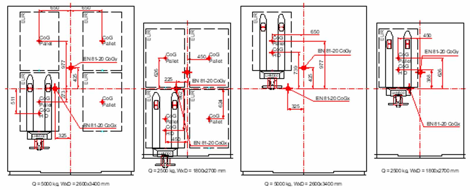
By using the two aforementioned load cases and properties of the handling devices, a loading analysis with EUR-pallet was done for elevator car sizes with 2500- and 5000-kg rated loads. In the analysis, there was always some clearance to car walls, so although conservative, the analyzed scenarios are not absolute worst-cases. The results are shown in Table 5. The areas of interest are the sill load and center of gravity. The sill load requirement is 60%·g·Q according EN 81-20 5.7.2.3.6 and 80%·g·Q according ASME A17.1 8.2.2.6. Since the weight of the handling device was part of the rated load, the 85%·g·Q sill load of EN 81-20 is not applicable here.
| Car load Q | kg | 2500 | 5000 | ||||||
| Car width x depth | mm | 1800×2700 | 2600×3400 | ||||||
| Handling device | Qty of pallets | Weight of pallet | Sill load1 | Center of gravity2 | Weight of pallet | Sill load1 | Center of gravity2 | ||
| kg | W | D | kg | W | D | ||||
| Manual pallet truck | 1 | 2395 | 69 % | 25 % | 23 % | 3000 | 43 % | 15 % | 18 % |
| 4 | 598 | 19 % | 1 % | 1 % | 1223 | 18 % | 1 % | 10 % | |
| Electric pallet truck | 1 | 1674 | 56 % | 25 % (17 %) | 13 % (16 %) | 2200 | 36 % | 15 % (11 %) | 13 % (13 %) |
| 4 | 418 | 18 % | 1 %3 (0 %) | 0 % (0 %) | 1043 | 18 % | 4 % (0 %) | 3 % (9 %) | |
| Electric reach truck | 1 | 1400 | 58 % | 12 % (7 %) | 3 % (8 %) | ||||
| Forklift truck | 1 | 1600 | 83 % | 23 % (8 %) | 2 % (9 %) | ||||
| |||||||||
Table 5: Analysis results for the different handling devices
The offset center of gravity from car center according to EN 81-20 is 12.5% in depth and width direction. The offset according in width direction according A17.1 Fig. 8.2.2.5.1 is 25%. As mentioned, in depth direction there is no explicit rule in A17.1. Among other things, the loads caused by the offset of center of gravity has an impact on the guide rail dimensioning and bracket spacing.
The following findings can be made of this analysis:
- 60%·g·Q sill loading may be exceeded with light-handling devices, provided that the rated load of the car is small and individual loaded pallets are heavy.
- 60%·g·Q sill loading can also be exceeded with heavy-handling devices, even if the weight of the handling device is considered in the rated load.
- The center of gravity assumption of EN 81-20 can be exceeded with single heavy pallets with small- and large-rated loads with most handling devices, while the offset of 25% according ASME A17.1 seems to cover well the scenarios with single heavy pallets.
- For multiple lighter pallets, both the sill load and center-of-gravity requirements cover the analyzed scenarios with ample margin.
Finite Element Model Analysis and Results
5.1 Model description
Finite element model (FEM) analysis consists of two different sling-car system models where the applied loading is varied between the EN 81-20 60% sill load case and the selected load-handling device, electric pallet truck.
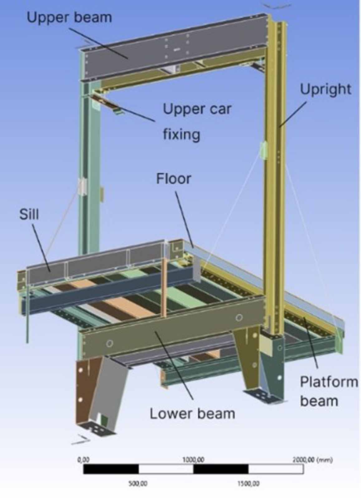
The critical components, which are the focus of loading analysis, are defined in the elevator standards and can also be identified as a result of the elevator level FEM analysis. The ASME A17.1 elevator standard identifies as critical components from the elevator loading point of view the sling upper beam, sling uprights, sling lower beam, sills, floor, guide rails and brackets.[4] FEM analysis helps identify the components that are under higher stress in different load cases. For example, ASME A17.1 does not identify the upper car fixing as a critical component from the loading point of view, but, depending on the fixing design, that is still a component under stress during the loading situation. With spring-isolated platforms, the applied sill load causes a horizontal force component to the upper car fixing where horizontal movement is restricted, and therefore causes stress. Hence, the upper car fixing should be considered in the analysis. The main components considered in the analysis are shown in Figure 4.
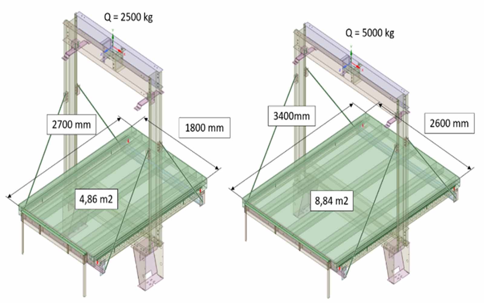
Two FEM models were modeled for the analysis, one considering rated load of 2500 kg and the other considering rated load of 5000 kg. The FEM models with the specified platform dimensions can be seen in Figure 5. Plywood material was used in the floor as the top surface. Other materials in the assembly are considered as structural steel.
Finite element mesh can be seen in Figure 6. Element size of 10 mm was applied. All the beam profiles and plate parts were modeled with shell elements. The sill profile was modeled with solid elements. All the bolts were modeled as beam elements connected to their holes by rigid elements, and no pretension was applied because it is not meaningful in this study. Frictionless contacts were used between the components, which are in contact with each other by bolt connection. Bonded connections or shared topology were used in case of welded connections. These were seen as accurate enough modeling methods considering the scope of the study.
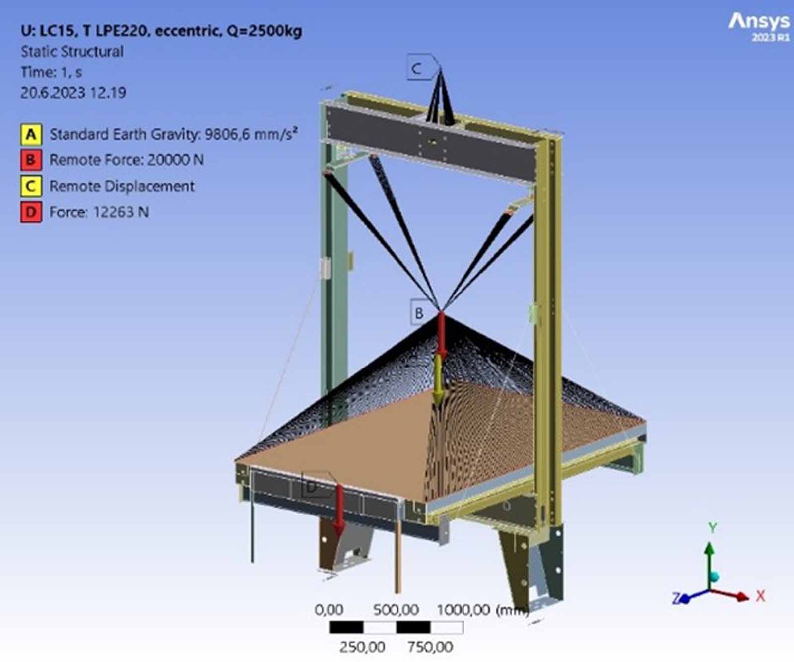
To represent the 1:1 suspension, remote displacement, where displacement was fixed in the Y-direction, was added to a remote point (C). The remote point was attached to the upper beam with deformable elements. The car mass was applied in a remote point (B) attached to the upper car fixings and three sides of the floor by rigid elements. For the Q=2500 kg model car mass 2000 kg was applied and for Q=5000 kg applied car mass was 4000 kg. Sill load was applied on the sill profile either on an area representing the wheel dimensions of the loading device (electric pallet truck load cases) or centrally as a line load (EN 81-20 load cases). The loads and boundary conditions are presented in Figure 7.
5.2 Results
The results used for the comparison between the different loading scenarios are presented in Figure 8. From the stress results, it can be seen that the upper car fixing and sill are the most stressed components during the loading of an elevator according to this study. The use of spring-isolated platform beams increases the moment in upper car fixing and, therefore, the stress levels are increased. The sill is under stress because the load is applied on the sill. The structure of the sill influences the stress levels in a way that the positioning of any stiffeners in relation to the wheeltrack of the load-handling device influences stress results. Therefore, the sill structure design should consider the used load handling device. The car floor displacement results include the total and Y-direction displacement of the floor structure during the loading. The displacement is a sum of deflection of different components and the compression of the spring platform springs during loading.
5.3 Conclusions
For the Q=2500 kg model, the stress values between the standard and electric pallet truck load cases were similar. The stress values are, in most cases, under the yield limit of the material. Since the purpose of this study was just to compare the different loading situations with a simplified sling structure, the safety factors are not considered. The use of standard loading for elevator design would not lead to a substantially overengineered solution even if only light load-handling devices are used.
For the Q=5000 kg model, the differences are more substantial. From the observed components, the highest variance in stresses can be seen in the upper car fixing and sill. This is to be expected, as the load is applied directly on the sill, which causes high stress in the sill structure. With isolated car platforms, the sill load also causes high moment on the upper car fixing.
When using light load-handling devices, the most critical loading caused is sill load even if the load is more equally divided between the axles compared to larger devices. Also, the number of wheels influences how the load is distributed. Smaller axle load causes lower sill load, which affects the elevator engineering. Of the standard sill-load cases, the EN 81-20 60% sill-load rule matches best with the light load-handling device loadings. For the high-rated loads, even the 25% rule from ASME A17.1 could be sometimes applicable with the light load-handling devices. It seems clear that engineering a high-rated load elevator with 85% or 80% sill loads could lead to unnecessary strengthening of the sill, car and sling designs in case only light load-handling devices are used. Also, trying to maintain car displacement at an acceptable level with high sill loads might lead to complicated and costly solutions.
The wheel track of the device and the position of the load on the sill have an effect, especially on the stresses on the sill and the interface between the sill and the floor. Since there is a large variance of different kinds of load-handling devices, defining a specific wheel track might not be meaningful. Instead, the worst-case based on the specific sill design should be checked. If one wheel track for light load-handling device needs to be specified, it should be something between 340 mm and 390 mm to match the commonly used pallets.
6. Discussion
From the pallet loading analysis, it can be concluded that, if the elevator is intended to be loaded with single heavy items, the EN 81-20 requirements are not necessarily sufficient. However, if the goods are loaded on multiple lighter pallets, then the requirements may lead to overengineering. Well-suited center-of-gravity estimates can lead to a reduction in guide rail size and an increase in bracket spacing.
The FEM analysis indicates that, for higher-rated load cars, using a light loading device as the basis for elevator engineering could be beneficial, especially in relation to sill load, but it is important to note that heavy loads can also be transported with light loading devices. Optimizing sill loads could lead to cumulative material saving over the whole elevator system.
To ensure minimized environmental impact, dimensioning both center of gravity and sill load correctly is particularly significant in high-rise applications, as the excess material consumption of many components is amplified by the travel height.
In order to not compromise safety while reducing material consumption, the maximum weight of individual goods should be an essential part of the elevator specification, and it should be clearly indicated to elevator users along with the maximum axle loading, which correlates to the sill load. Finally, it would be of general interest to develop the global elevator standards to take the light handling devices into consideration and use standard pallets as the basis of dimensioning rules would aid the customer in defining their vertical-transportation needs.
7. References
[1] R. Roberts, “Control of high-rise/high-speed elevators,” in Proceedings of the American Control Conference, pp. 3440-3444, Philadelphia, 1998.
[2] “EN 81-20 Safety rules for the construction and installation of lifts – Lifts for the transport of persons and goods – Part 20: Passenger and goods passenger lifts,” European Committee for Standardization, 2020.
[3] W. Musial, P. Beiter, P. Spitsen, J. Nunemaker, V. Gevorgian, A. Cooperman, R. Hammond and M. Shields, “2019 Offshore Wind Technology Data Update,” National Renewable Energy Laboratory. nrel.gov/docs/fy21osti/77411.pdf. 79 p, Golden, CO, 2020.
[4] “ASME A17.1/CSA B44 Safety Code for Elevators and Escalators,” The American Society of Mechanical Engineers, 2019.
[5] “Eurocode 1: Actions on Structures – Part 1-1: General Actions, Densities, self-weight, imposed loads for buildings,” European Committee for Standardization, 2002.
[6] “Industrial trucks – Terminology and classification – Part 1: Types of Industrial trucks,” International Organization for Standardization, 2015.
[7] S. Mudiyanselage, P. Nguyen, M. Rajabi and R. Akhavian, “Automated Workers Ergonomic Risk Assessment in Manual Material Handling Using sEMG Wearable Sensors and Machine Learning,” Electronics 2021, vol. 10, no. 2558, p. 14, 2021.
[8] M. Hoozemans, A. van der Beek, M. Frings-Dresen, F. van Djik and L. van der Woude, “Pushing and pulling in relation to musculoskeletal disorders: a review of risk factors,” Ergonomics, vol. 41, no. 6, pp. 757-781, 1998.
[9] T. M. H. Europe, “Platform lowlifter truck 2.0 – 2.5 ton,” [Online]. Available: toyota-viljuskari.me/1557402996-bt-levio-lpe-200-220-250_HI.pdf. [Accessed 9/22/2023].
[10] T. Inc., “What Are The Standard Pallet Size Dimensions?,” [Online]. Available: tranpak.com/faq/standard-pallet-size-dimensions/. [Accessed 2/22/2023].
[11] T. M. H. Europe, “Hand pallet truck 3.0 ton,” [Online]. Available: media.toyota-forklifts.eu/published/24114_Original%20document_toyota%20mh.pdf. [Accessed 09/22/2023].
[12] S. GmbH, “FM-X Technical Data Driver Seated Reach Truck,” [Online]. Available: data.still.de/assets/products/Vehicles/Reach_Trucks/FM-X/pdfs/FM-X_EN_TD.pdf?mod=1603103060&download=1&s=b0298c61ff3f4555ff557e3880df433b. [Accessed 09/22/2023].
[13] T. M. H. Europe, “Electric powered forklift 1.5 – 2.0 ton,” [Online]. Available: media.toyota-forklifts.eu/published/21447_Original%20document_toyota%20mh.pdf. [Accessed 09/22/2023].
Get more of Elevator World. Sign up for our free e-newsletter.


