Elevator Selection and Analysis in 1898, Part Two
Sep 1, 2012
A look at how William H. Bryan addressed questions at the December 1898 meeting of the New York Chapter of the American Society of Mechanical Engineers
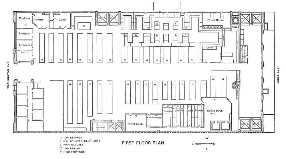
Part one of this article discussed the development of the specifications for an elevator system required in an eight-story “modern commercial building” (ELEVATOR WORLD, August 2012). This subject was a primary topic in a paper titled “The Mechanical Plant of a Modern Commercial Building” presented by William H. Bryan (1859-1910) at the December 1898 meeting of the New York Chapter of the American Society of Mechanical Engineers (ASME). Part two will address the bidder’s response, changes to the specifications, machine selection and the testing that occurred to determine if the manufacturer had met the “contract guarantees.” The specifications called for eight (two passenger and six freight) elevators to be located along the perimeter of the building. The passenger elevators (numbered “1” and “2” in the plan) were located along the southwest exterior wall of the building.
Bryan, who had been one of the lead engineers on the project, noted that of all the bids received for the building, “the selection of the elevator system presented the greatest difficulties.” He also reported what is, perhaps, a familiar scenario today – all the elevator bids were viewed as “excessive in price.” The solution was to revise the specifications and solicit new bids. The elevators’ capacities were revised in table 1.
However, the freight elevators were to be designed “to be capable of carrying” the originally specified loads “at reduced speeds.” The bidders also were allowed to substitute wooden rails in place of steel guide rails, the maximum cost of the passenger cabs was reduced from US$300 to US$200, and the “indicators” were to be eliminated. The latter change serves as a reminder that a wide variety of elevator features were viewed as “optional” in the late 19th century.
The second round of bidding followed the same format as the first in that bids were solicited for steam, hydraulic and electric elevator systems, a fact that emphasized the presence of competing older (steam), current (hydraulic) and new (electric) technologies. The engineers, architects and clients chose to accept the bids for the electric elevator plan. According to Bryan, this selection was the result of a “thorough investigation” that revealed these elevators would “be more economical. . . on account of the light loads usually carried.” He also noted this selection resulted in “some saving in first cost” and a “much more compact arrangement in the engine room.”
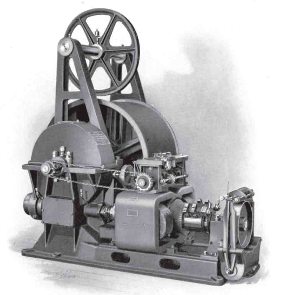
The contract was awarded to Sprague Electric Elevator Co., which specified its Type X38 model for the two passenger elevators and two of the freight elevators (1500-lb.-capacity machines) and its Type Z model for the other four freight elevators (1800-lb.-capacity machines). Both were drum machines that featured tandem worm gears, with the primary difference being the use of solenoid control on the Type X38 machines and pilot motor control on the Type Z machines. Sprague Electric Elevator said it could provide the eight elevators at a cost of US$22,070, and the required additional engine, dynamo and “appurtenances” for an additional US$3,134; thus, the total cost was US$25,204.
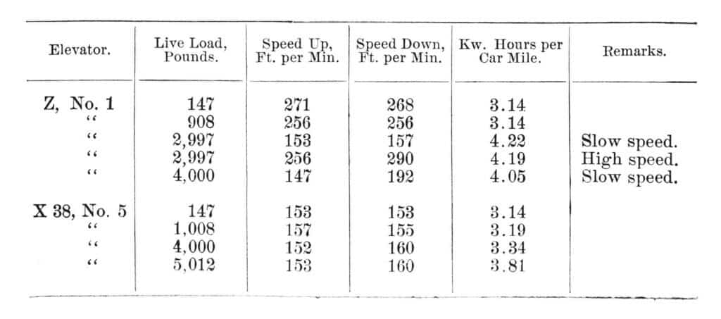
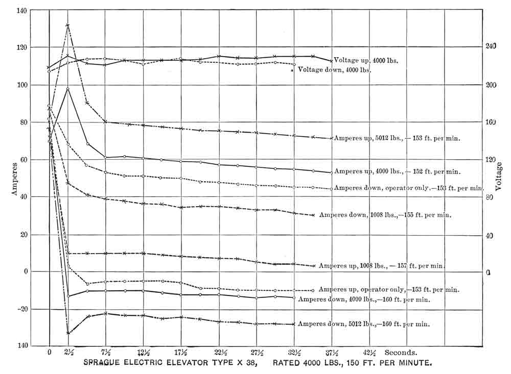
Following the elevator installation, Bryan oversaw a series of tests that sought to “determine whether the contract guarantees had been met.” One Type X38 and one Type Z freight elevator were subjected to “exhaustive” and “detailed tests of capacity, speed, and efficiency.” The tests employed four methods. For the various load tests, the live load was obtained by weighing. Voltage, speed and current were measured by “simultaneous readings” taken at “2.5 s. intervals,” with the current being “checked by two instruments, two observers reading independently.” The “speed of travel” was calculated by “dividing the revolutions of the armature by the known ratio between the speed of the armature and the speed of car.” Finally, the “power consumed per trip” was obtained “by plotting the curves of the current readings, the arc of which – multiplied by the voltage – gives the watt hours per trip. This was reduced to mile of travel by multiplying the watt hours per trip by the fraction that one round trip is of 1 mi.” Bryan used this data to produce a table that indicated the kWh per car mi. for various loads and speeds, and a graph that plotted the “observed data” of the Type X machine for three load conditions at both low and high speeds.
A wattmeter placed on the switchboard measured the electrical power consumed by the elevator plant. Records were kept for the period between July 12 and July 27, 1898 (138.5 hr. of operation). During this period, the “electrical power used by the eight elevators” was “1,920 kilowatt hours, or an average electrical horsepower per hour of 18.6 for the plant, or 2.3 horsepower per elevator.” For the full month between July 2 and August 2 (283.5 hr. of operation) the “average electrical horsepower was 19.2, or 2.4 per elevator.” Interestingly, no records were kept of the travel distance. Bryan claimed he could estimate the distance traveled for the period between July 12 and 27 as follows: he assumed an average efficiency of 4 kW per car mi.; thus, 1,902 kWh divided by four yielded a mean travel distance of 480 mi.
Bryan then determined that if each of the eight elevators made one round trip, the total distance traveled would be 1,608 ft., or 0.304 mi. Bryan divided the mean distance traveled (480 mi.) by 0.304 to find the number of round trips that occurred in the 138.5 hr. of operation: 1,576 total. This was further broken down into 11.4 trips per hr., which equaled 5.25 min. per round trip. Bryan believed this estimated travel time exceeded normative working conditions. He noted the average round-trip travel distance was 201 ft. and that the average speed could be assumed to be 200 fpm; thus, he claimed the average round trip could “have been made in about a minute.” In this estimate, Bryan failed to account for time associated with the elevator doors opening and closing and time spent loading and unloading the car. Nonetheless, he used his estimated travel time to determine the elevators “averaged” about 20% of their “time in motion,” instead of the 30-50% that had been “originally assumed for maximum service.”
Bryan also reported that, when first installed, the elevator engine “starting devices” were “set at 2.5–3 seconds,” which resulted in the starting current exceeding the running current by more than 50%, which exceeded the specifications. However, the assumed specification start time had been set at 5 s.; when the starting devices were reset to this time, he reported, “This condition of the specification was practically met.” With regard to this particular parameter, Bryan noted it impacted both energy usage and passenger experience:
“It is a question of judgment, therefore, whether the tenants prefer a slow and easy start and a smooth-running electrical plant, or a quick start and correspondingly severe and sudden demand upon the dynamo and engine.”
Following his presentation, the members of the New York Chapter of the ASME engaged in a lively question-and-answer session. The group included Charles R. Pratt (co-inventor, with Frank J. Sprague, of the electric screw-driven elevator) and George H. Hill, an engineer employed by the Sprague Electric Elevator. This discussion, recorded and published with Bryan’s paper in the society’s proceedings, was similar in tone and content to those that occurred at Elevcon USA 2012 (EW, August 2012). This serves a reminder that investigations into elevator operation and efficiency have been an aspect of system design, application and evaluation for a long time.
| Original Capacity | Revised Capacity | Maximum Speed | |
| Two Passenger Elevators | 2500 lb. | 1500 lb. | 300 fpm |
| Two Freight Elevators | 3500 lb. | 1500 lb. | 225 fpm |
| Four Freight Elevators | 4000 lb. | 1800 lb. | 150 fpm |
Get more of Elevator World. Sign up for our free e-newsletter.
