Elevator System Weights – A Critical Mass
Apr 1, 2024
Measurements and related calculations are examined in depth.
by Kevin Heling
Value: 1 contact hour (0.1 CEU)
This article is approved for Continuing Education by NAEC for CET®, CAT® and QEI credit and by NAESA International for QEI.
EW Continuing Education is currently approved in the following states: AL, AR, CO, FL, GA, IL, IN, KY, MD, MO, MS, MT, NJ, OK, PA, UT, VA, VT, WA, WI and WV | Canadian Province of BC & ON. Please check for specific course verification of approval at Elevator Books.
Learning Objectives
After reading this article, you should have learned about:
- Elevator masses (and also weights), which are important aspects of safety for traction elevators, though they also come into play with hydraulics elevators.
- The distinction between mass and weight; how these values are used in elevator design and initial build and how they can impact performance and safety of an elevator after installation and relative to service.
- That the Safety Code for Elevators and Escalators (ASME A17.1/CSA B44) in recent revisions has made some changes that get us thinking about mass and weight.
- Weighing already installed equipment (cars, counterweights [CWT] and compensation if part of the system) is not an easy or inherently reliable process. Technicians must be properly trained in how to do this.
- Mass and weights (used to measure force) in elevator systems are integral to understanding CWT overbalance and the effect/impact on stopping forces (of safeties, machine and other main brakes, emergency brakes, buffers). Traction is also another issue, as well as load effects on system wear, which ultimately influences safe operation and maintenance of elevators. Discussion and learning these topics help one understand how changes in safety code requirements are an improvement.
Elevator system weight (mass) measurements and related calculations have always been a critical issue in the design, installation, expected performance and maintenance of elevators. Elevator engineers and knowledgeable field technicians agree. This important issue should be getting ever-increasing attention. Let’s look at this topic in detail and together make sure “it is.”
Following are examples of the importance of elevator system weights and some further information supporting this use of your time and attention:
- Current and recent designs of elevators are taking advantage of new materials technology (including, for example, honeycomb panels or thinner metals for cabs, smaller machines with lower torque and horsepower but higher RPM and small sheave diameter). These create situations (some unexpected) where originally designed balancing between the counterweight (CWT) and the elevator car (cabin) has become a tighter and less-forgiving dimension. This demands a higher level of absolute weight accuracy. Further, we know and have experienced other impacts on system performance. There are some interesting impacts. There is no room for that discussion here, but they are good topics for future education.
- ASME A17.1-2013/CSA B44-13 and later, the Safety Code for Elevators and Escalators, recognized a need for improved and more technical safety testing of elevators (Category 5 (Cat5) when Alternative Testing was added. As authors of the Safety Code, we think to deliberately choose to add weighing masses as the first step in CAT5 Testing. This was not a consideration for almost 60 years during periodic testing until alternative testing was added. Going forward, we will refer to the new CAT5 testing as “electronic” testing. We will be focusing on safety as a practical matter — that periodically measuring masses and concurrently evaluating system balancing is worth doing. There is another related Safety Code addition — ASME A17.1-2019/CSA/B44-19 Section 2.24.2.3.5 — requiring that CWT overbalance is documented on a crosshead data tag. At the end, we will show this relevant code language.
- Many AHJs (Authorities Having Jurisdiction) in the U.S. and Canada are aware of the effects that changes/variances in elevator system masses (any time after original installation) have on the safety and performance of installed elevators. Some AHJs require system masses, or at least car weights, to be checked pre and post any alteration if there is a potential weight change of greater than 5%. The new weight measurement must be formally reviewed and approved by a professional engineer.
- Experience has shown that the process of weighing installed elevator equipment (car and CWT) is not an easy or inherently reliable process. During weight checks, the industry sees that it is very common to find car (and CWT) weights different enough from the original design that it impacts performance, wear and corresponding operating safety. Sometimes, this will explain poor ride quality and component wear or early failure. We are aware of cases where engineering/R&D of a few major elevator manufacturers and field operations staff of many independent service companies have taken the time to go into the field to make a specific effort to validate system masses on recently installed elevators or legacy elevators under their maintenance program.
These key points and a lot of recent experience support a good review of the process of system mass verification. Accuracy, reliability and repeatability of the process are key.
Over at least the past 15-20 years, this writer and many more experienced colleagues have directly reviewed many (certainly hundreds-plus) traction installations in the field, specifically looking at system masses. We have seen that performance is affected, first with the effect of weight (force and load distribution) on elevator suspension ropes (or means) and the overall suspension means system. Some of what has been seen is a clear safety concern; many were investigated because of unexpected increased wear in components of the suspension means system. We started out looking at this from the point of view of rope — manufacturing, design, installation and ultimate performance. In this early phase, we found ourselves wishing for a tool that would measure elevator system loads with statistically reliable accuracy. Experience then led us to understand that when/if we did get a good weight measurement of the car and the CWT, there was no clear connection to the effect on the system. Sometimes, even after a completed CAT5 test and maybe a detailed engineering review, issues were not understood. We still needed to make estimates, which often were not validated, which meant that the effects of a balance percentage that was no longer optimal were not connected or accurately considered. But, we were still seeing some big effects.
As a technical introduction, we start with a basic explanation of what is weight and what is mass. These terms are often used interchangeably, suggesting they mean the same thing. While this is usually okay, technically, they are not the same. One can search reliable references, even Google the terms “mass” and “weight” in elevators and find them correctly and technically explained. You will find that mass is a property of matter and is the same everywhere. Mass, measured in grams or kilograms, is always something that is greater than zero. While similar, weight is correctly measured in Newtons and does not have to be more than zero; it can also be zero or less. Weight is a key component of the measure of force using the equation W=m*g, where m equals mass and g equals gravity. For relevant discussions about elevators, 1 g is equal to 9.81 meters per second squared (9.81 m/s2 or 9.81 m/s/s). 9.81 m/s2 is the commonly known value of 1 g on Earth. Thus, for our purposes, if the mass of something (i.e., a passenger on an elevator car) is 100 kg (220 lbs) then the force (weight) of that mass is 100 times 9.81, which equates to 981 Newtons (981 N). In later discussions, you’ll be shown that this basic building block of measuring Force (F) is used in algorithms adhering to the principle of Newton’s Second Law of Motion. We could go into this in detail and give some interesting and further examples, though they may be sleep-inducing. We won’t do that.
It is enough for our purposes now to know that both mass and weight (force) are important values in elevators that will affect the safe operation and performance of all elevators. As already noted, a summary discussion of ASME A17.1 (2013)/CSA B44-2013 and forward revisions of the Safety Code for Elevators and Escalators have added alternative testing. Elevator system masses are integral to alternative (electronic) test measurements. The authors of our “Safety Code” were and are aware of the importance of elevator system masses and an understanding that masses should not materially change from the original design. If they do, it’s not just a good thing, but probably a necessity, to measure and know the impact and related risk associated with changes (deviation from design). In CAT5 testing, we know that the slide distance for safeties was calculated using 50% overbalance. Frequently today, we find in the field that weights have changed (and thus, of course) so has the overload balance. There is no way with simple weight testing to know what impact this has on the safeties’ slide distance. This is why it’s important to measure system weights as accurately as possible.
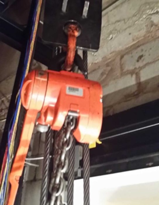
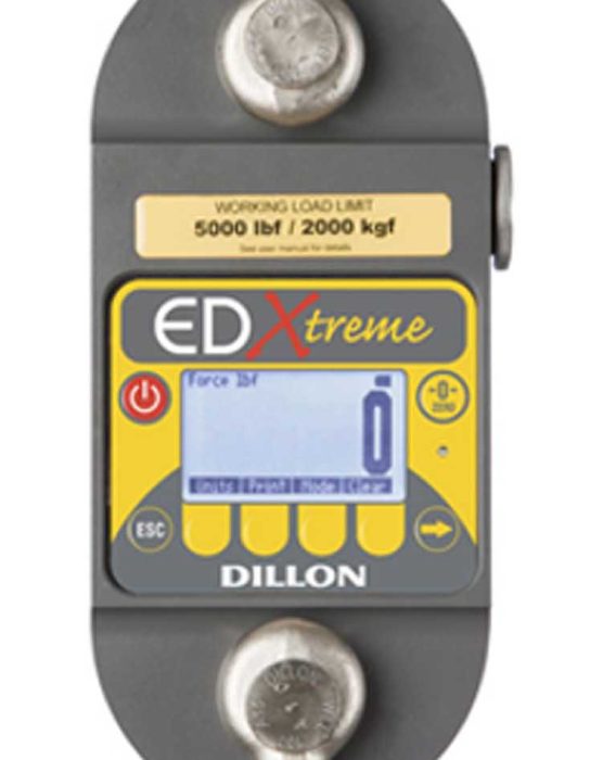
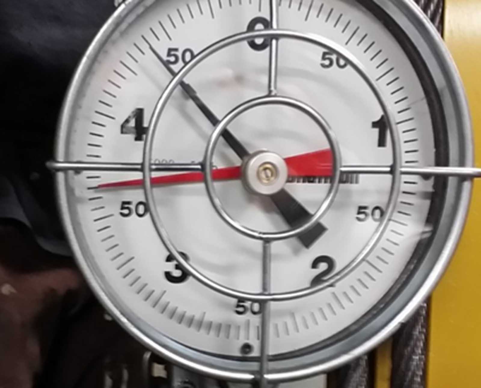
Before new weighing (force measurement) tools began to be introduced, the only method available for weighing installed elevator equipment was a method of hanging the car (and then separately the CWT, maybe from a beam at the top of the hoistway using a chain hoist and a dynamometer (crane scale). Below that, a proper capacity sling must be used to lift and hold the car or CWT. This method, at best, is a difficult process and unsafe, not to mention hard work. In many installations, the existence of an overhead beam and assurance of requisite lifting and holding capacity was sometimes not assured or available, so this method couldn’t be used. Further, lifting either the car (or worse, the heavier CWT) by the combination hoist and dynamometer is precarious and unsafe for elevator mechanics and helpers. Hoisting from the top of the car or somewhere else in the hoistway creates a safety concern. With this method, there was not a good means of measuring compensation (ropes or chains) if they happened to be a component of the system masses. This method was and is subject to variations in the measured load tied to bad or non-existent estimates of other included masses, or lack of attention or time put into getting good measurements. Estimates were made. Then, there was also the real and potential existence of held friction as the car or CWT balanced or “worked” against rails (through guide shoes or bad rollers) or was held in the ropes related to friction with the sheave. This, we now know, can cause plus or minus errors in force (weight) in the range of 300- to 500-lb force and, in a few cases, combined effects can further increase that variation.
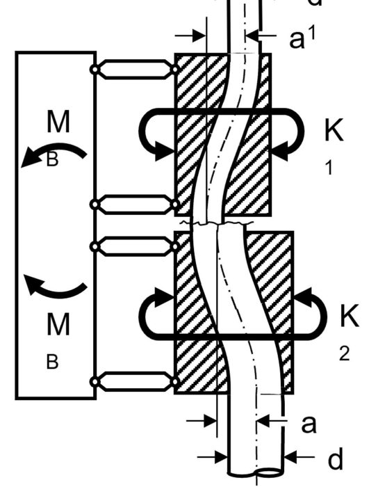
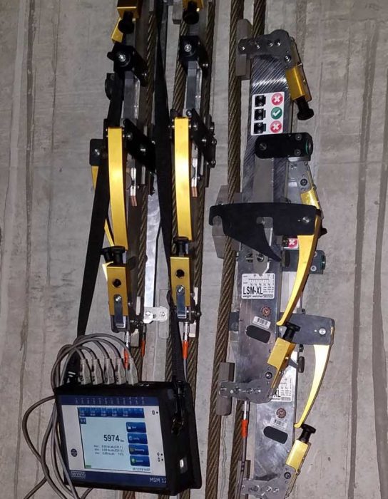
Development and use of a rope-shortening clamp (commonly available tool) made this process simpler. It’s still hard work, as a 50- to 70-lb clamp assembly must be lifted and held overhead by a technician(s) standing on top of the car as ropes (above the car or CWT sling) are fitted into the clamp and the device is tightened into place. Also, there are a few industry “rope geeks” who worry that ropes clamped into Roebling devices are being additionally stressed at that point in the rope (just above the car and the CWT). We saw installations using this method where weight forces were measured incorrectly. Training in this process was either incomplete, not understood or just not followed. We saw cars suspended on rope clamps during weighing, but the counterweight was not landed. This meant that the weight measured was dynamic (ropes on traction sheaves could move, even if ever so slightly) and potentially the weight was high or low (depending on the last movement of the car up or down). We know the error in measurement could again be in the 300- to 500-lb range. We also saw one instance in New York where tie-down compensation ropes were not released while the car was hoisted up on ropes using a lever hoist and the rope clamp! This meant they were not weighing the car; they were measuring an increasing force pulling against the fixed compensation.
Now, let’s give some thought to what a 300- to 500-lb variation would mean in terms of elevator system balancing. The simple calculation is the product of CWT minus car weight divided into the car capacity. Example using round numbers: 6000 lb (CWT) minus a 4500-lb car = 1500 lb. 1500 lb divided into a 3000-lb capacity car is “balanced at 50% of capacity.” Typically, we have seen cars “optimally” balanced somewhere between 40% and 50%. That range was considered common on traction elevators in the past. Now, with machine-room-less (MRL) systems, balancing seems to be narrowly set around 50% (for optimal operation). The best balance percentage is determined by engineering in the design phase of elevator systems. With variations in loads and measurement variations, we’ve already mentioned things that can happen. A traditional way to check CWT overload balance has been to load the car by 40% or 45% or 50%, based on the expected overbalance of the CWT. That way, when the brake gets picked, it can be observed in which direction the car moves, indicating the side with the greater mass. Methods like this work, though in an imprecise and broad sense. In terms of operating safety, we can and should have accurate data/information with respect to balancing. To give you an idea of the effect of a variation of mass, here is a straight example of what can be encountered with faulty mass/load measurements. Using the weight and balancing example above, consider an example similar to some situations we have seen. The car weight is positive by 300 lb and the CWT weight is off by 300 lb on the negative side. This is plausible, understanding that the car was moved up to the position where it was weighed (mid-hoistway is best; this is logical with respect to “balance”) and, correspondingly, the CWT was moving down. The two weights potentially have countervailing results related to held friction. The balancing calculation is then CWT (5700 lbs) minus car weight (4800 lbs); the product is 900 lbs divided into the car capacity of 3000 lbs. This gives us a 30% load balance. If we “decided” this was a correct measure, we would expect some operational evidence of the imbalance (i.e., ride quality, stopping forces in the main and emergency brakes effected and some impact to safety stopping distance). If weight was then added to the CWT to correct the imbalance, it may be a positive solution, or maybe it would then have further impact on stopping forces or an impact where there wasn’t one before. We could consider operating effects if the CWT overload balance went the other way (to 70%).
The effect is real, and the impacts may be seen in performance (sometimes not) and should be observable during CAT5 testing. Right? Again, maybe not. Sometimes, the effects are less dramatic but still cause damage over time. To know, we must be sure our mass measurements are statistically correct. There is a tool system we have used that we know handles this. We refer you to an article in EW in the May 2015 issue titled “A ‘New’ Way to Weigh.” Again, we won’t fill this page with repeated information; a key takeaway is that training and adherence to correct processes is important. As we all know, correct tools and correct use drive results.
You can dig farther into this by looking into the effects of measured results using an alternative testing method and considering how it compares to CAT5 testing using the “old standard” method of taking stopping measurements using full load. This advance in technology and testing method uncovers some serious measurement issues (false positive is our biggest worry). We’ve seen limitations and easy mistakes coming from the full-load method. Those who have investigated this with an open mind and considered all the technical aspects understand that alternative testing (using a current and established accurate measure of mass) is an electronic method with measurable and discrete data output. For this important reason, it is more accurate, reliable, meaningful and discerning. With data (starting with mass measurements), steps can be taken to fully understand if there is a problem in the system with forces. You will also see effects and impacts in the test results. At its foundation, electronic testing gives us — data. At its best, full-load testing is mainly a visual observation and is only able to show us what may happen with an elevator carrying a full load. There is no insight into actual stopping forces when we have much less than a full load (which is most e-stops). We have no information or data (other than to observe stopping in the case of safeties, and maybe that deceleration exists in the case of brakes). With data, the steps to technically knowing and validating elevator system masses, balancing and the directional impact (safety) of the testing we do is possible. Data, when looked at and used, takes us to a clearer understanding of the system. We are also able to see changes and impacts over time. Connections, relationships — as well as causes and effects — can be understood. Remember that the data comes from algorithms developed by engineers using Newton’s Second Law of Motion, a key principle of physics: F = MA (where F is Force, M is Mass and A is acceleration). This makes it clear how important it is to know and measure system weights.
We have seen and now understand there are related issues with full-load tests. With full-load, we now know that observed measurements are affected by load variance (unknowable with rudimentary load-testing). We see the effects in tests conducted higher or lower in the hoistway or also related to the stiffness of the suspension means. These effects are mentioned so they can be considered as part of remedial action. Electronic testing with accurate algorithmic measures of masses and stopping forces more than replaces the broad estimates we get with only an overload test (the long-understood “worst case”). What we have been doing in CAT5 testing until now (with weights) is not giving us the expected sense of safety and security we think it is. To be clear, full-load testing gives us very little and, as we have shown, sometimes inaccurate information. There are technicians out there who think that the work of bringing weights into an occupied building means lost “work” for them. Using technology, which is what advanced elevator technicians are all about, really means that elevators are tested better and more meaningful maintenance can be done. This is where our time and effort should be.
Twenty to 30 years ago, new tools were coming out. Process-focused service and repair technicians were trying them. Some were found to be capable of statistically accurate measurements of weight (and masses therefore) and some (many?) were not well-designed and/or required careful, maybe impossible, attention to their use; they usually required extra steps. Their accuracy is found to be plus or minus 25% or worse. It is not the point of this article to review those processes, experiences or even those tools. Bad experiences frustrated the kind of technical information and validation we are talking about here. The 2013 revision of A17.1/B44 pointed us back in this direction. Essential knowledge is that weight/mass is important, and that’s our focus with this training. Let’s continue considering the effects and impacts of mass variations occurring after or outside of the original elevator system engineering and design.
Putting our discussion into field operational terms, the mechanical functions that can be measured and recorded (and further investigated) include traction (see Sidebar No. 1), machine braking and emergency braking, impacts/effects of an emergency-stop brake on buffers and safety stopping (normal with suspension means in place and now, with alternative testing, catastrophic in the case of emergency stopping if there were a complete loss of suspension means) and impacts/effects of an emergency stop on buffers. It’s a fact that the CWT assists the safeties in CAT5 tests with weights. This is another direct support for getting accurate weight measurements. With electronic testing, an algorithm tells us exactly the amount of safety “assistance” is coming from the CWT with intact ropes (or belts). That assistance is effectively a spring effect. With electronic testing today, that can be measured and known. Many in the industry are surprised to find that there usually is not enough stopping force in safeties to stop a freely falling car. This is a fact that we don’t want to happen, and, fortunately, it doesn’t happen often. Now we have a measurement that points this out for us.
It is critical to know the weight of a cab before and after an alteration. This has been a mandated part of the code for decades. If you change the weight of a cab by 200 lbs by replacing a door operator (typically lighter these days) or change the cab interior (also usually minus, but can be a weight increase), there must be a calculated adjustment with the weight of the CWT. It is important to understand and maintain a reasonably correct overbalance. Change will affect the system mass and thus, traction and braking/stopping forces. It will affect all needed forces mentioned above. We never want to compromise (or worse, eliminate) the factors of safety that were originally designed into the elevator system (see Sidebar No. 2.) We should mention that additional mass can be an issue with sheave shaft load on a drive machine, selecting and setting roller guides, and — very importantly — with selecting and sizing safeties, as well. Engineering must be involved in all these situations.
The system load, specifically the balance ratio, affects motor currents through the load ranges the elevator needs to operate. For example, some VVVF (variable-voltage, variable-frequency) drives use load to tune output/reduce current to the motor. This affects ride-quality, and the reduction of current can extend the life of drive and machine components. An industry expert suggested this reference as an example: Magnetek HPV900 APPENDIX-Adaptive Tune (hpv-900-series-2—ac-pm-tm7333-r22.pdf cmco.com).
We have had experience and discussion on the real option of using motor current measurements to validate a balanced load, and even using a simple hand movement of the elevator cab when it is resting shackle to shackle with the CWT. Both are reasonable and legitimate. Caution still needs to be taken to identify and know if there are friction impacts in play (i.e., gear “stiction” for geared elevators). Actual weight measurements are not automatically given; a correct calculation of the comparison of the current is possible, but the calculation is a little complicated and errors can be made. Correctly determined weights are a key tool for validating and evaluating performance of the elevator system.
While pulling together information for this article, we were advised that, with an elevator controller that is sophisticated enough, load and balance information should be available. As an accurate weight is required and load sensors used, the method must be proven and up to these challenges. Until recently, the availability of reliable devices was difficult. With such equipment, weights are typically monitored on just one side — the car side. Using reliable devices to measure rope/suspension means tensions (load force) on each side and evaluating the differences is a more accurate approach. Going forward, we know that CAT5 testing on some new or existing elevators will have the benefit of permanent overload (donut-design) sensors (direct pull) on the car side. This can accurately measure car weight (anywhere in a full run). Adding donut sensors on the CWT side would give us all load information needed dynamically. CWT weights don’t normally change, so this may not be necessary. It would be easy to go out (probably one time) to get the CWT side measurement so it is known and assured correct (for testing purposes) going forward.
Sidebar No. 1: The Eytelwein Relation
by Tim Ebeling
The principle of the rope-driven elevator is based on traction. It is not for nothing that these elevators are called traction elevators.
Traction is defined by the Eytelwein relation. This looks a bit complicated at first glance — but it’s not at all. The right side of the relationship may be a little difficult. The Euler number is the power of the product of the coefficient of friction between the ropes and the traction sheave groove and the angle of the rope’s wrap around the traction sheave. Ultimately, what every good elevator mechanic knows: The more wrap (e.g., double wrap) the rope has around the traction sheave, the more traction the system has. The more friction is generated, for example by V-grooves with an undercut between the rope and the traction sheave groove, the more traction the elevator has. We don’t need to worry much about this part of the equation because the left side of the relation is much simpler. It says that the ratio of the masses of the counterweight to the empty cabin or the ratio of the fully loaded cabin to the counterweight must be less than or equal to the righthand side of the equation.
Eytelwein equation
This means that traction is ultimately defined by the ratio of the two masses! During the construction of the elevator, these masses are specified and the corresponding traction sheave grooves, number of ropes, wrap angle, etc., are specified. It’s easy to imagine what would happen if, for some reason, this mass no longer corresponds to the original design, for example because the cement counterweight has dried out or the cabin has new door drives or liners, etc. In such a case, this modified elevator system requires different traction (since the mass ratio has changed, i.e., the left side of the relation). But no one changes the number of ropes, the type of traction sheave, the wrap angle or anything similar. This can easily result in a dangerous operating condition. It’s obvious why knowing the real mass is so important!
Tim Ebeling is chief engineer/managing partner at Henning GmbH of Schwelm, Germany.
The information covered here shows us the many possibilities related to elevator system masses at the outset and then on through physics and the laws of motion.
In closing, I want to provide here the following.
Sidebar No. 2: Disaster Avoided
When measuring masses prior to testing, we can properly observe the engineered ratings of the devices to be tested before testing with damaging results. The ELVI 2 electronic CAT5 system prevented me from performing a series of tests that could have devastated an installation had we used the conventional test weight method. We measured the counterweight mass of the service elevator at a downtown office building to be more than 12,000 lbs, while the buffer was only rated for 10,000 lbs. This information, when relayed to a tech support agent, triggered an engineering review of all 13 elevators in the complex. The engineer asked me for the masses of all the cars and counterweights, and what he discovered was alarming. It turns out the cab weights of the high rise and low rise had been altered from their design weight by a third-party contractor sometime between the years 1988-2015. In 2015, a full modernization was started on all 13 devices. However, when the elevator contractor submitted design criteria to their engineering department, they did not physically measure the masses. They simply used the design weights from the installation drawings assuming nothing had changed. This turned out to be a large oversight, since the car’s original design weight was more than 1,000 lb less than the actual measured mass. The engineer advised me that, because of this missed information during the design stages, the machine beams in the high rise were not rated for the new machine that was selected and needed to be reinforced with gussets bolted in place every nine inches along the beam. The low-rise machines were figured to be using too few hoist ropes, causing the groove pressure to be too great and explaining partly why the ropes were reaching rejection stages earlier than expected. Lastly, the service elevator, the most important elevator in the building and the elevator that triggered the review, needed the most work. This elevator had a unique design. I was told it was one of a kind in the country. This device is a basement traction with the machine room below the pit and a 2:1 double wrap roping arrangement complete with a gearless machine supporting 6500-lb capacity. This service elevator, I was told by the adjuster, during the initial acceptance inspection folded the platform during a full-load, full-speed car buffer test. The field staff then had to replace the platform and reinforce it with multiple lengths of C channel welded across the bottom. This obviously increased the weight of the car. To keep the current draw of the motor under the nameplate, they added extra weight into the counterweight frame — never actually measuring the new completed weight of the counterweight or the car. When I measured the masses of this car and counterweight and submitted them to the engineers, the list of work was staggering. This was a big concern, considering this car had been running like this for 30-plus years. The engineers told us the counterweight buffer needed to be replaced, and the car safeties had to be upgraded to a model that could handle the added weight. Now, had I simply put the load in the car and attempted these tests, or worse, these safety devices needed to work in a real-life catastrophic failure, the end results would have been devastating. — Name withheld (adjuster for an elevator service contractor)
“Reprinted from ASME A17.1-2022/CSA B44-22, by permission of The American Society of Mechanical Engineers. All rights reserved.”
8.6.11.10.3 Alternative Test Method Procedure. The alternative test method shall:
(a) include requirements to obtain and verify car and counterweight masses if necessary for the test
(b) have a procedure document that
(1) defines the permissible equipment range and limitations regarding use
(2) establishes monitoring and calibration criteria for tools or measuring devices as appropriate
(3) defines the test setup procedure
(4) provides instructions on how to interpret results and correlate the results to pass–fail criteria
(c) describe how to correlate no-load test results with previously acquired full-load and no-load results if necessary for the test method
(d) be included in the MCP [see 8.6.1.2.1(a)]
(e) include the information required by 8.6.1.2.2(c)(2) where applicable
(f) require a report conforming to 8.6.11.10.4
8.6.11.10.4 Alternative Test Method Report. The alternative test method report shall:
(a) identify the alternative test tool (make/model) used to perform the test
(b) identify the company performing the tests, names of personnel conducting and witnessing the tests and testing dates
(c) contain all required printouts or record of tests required to demonstrate compliance with the testing requirements that were gathered during an acceptance test
(d) identify which results from the baseline test are to be used for future compliance evaluation if necessary for the test method
(e) record the car and counterweight masses that were obtained per 8.6.11.10.3(a) during the acceptance test and during any subsequent Cat 5 test if required by the test method
(f) contain all subsequent Cat 5 results with pass–fail conclusions regarding Code compliance
(g) remain on-site or shall be available to elevator personnel and the authority having jurisdiction
ASME A17.1-2019/CSA B44-19, by permission of The American Society of Mechanical Engineers. All rights reserved.
2.24.2.3.5 Percent Counterweight Overbalance Data Plate. The designed maximum and minimum percent counterweight overbalance range that is required to meet the traction requirements of 2.24.2.3.1, 2.24.2.3.2, or 2.24.2.3.3 shall be provided on a data plate. This data plate shall be integral with or adjacent to the data plate required in 2.16.3. Where this data plate is adjacent to the data plate required by 2.16.3, the material and markings shall conform to 2.16.3.3.
NOTES:
(1) The percent counterweight overbalance is the percentage of an elevator’s rated capacity that the counterweight is heavier than the car.
(2) The percent counterweight overbalance range refers to the upper and lower limits, expressed as a percentage of the elevator’s rated capacity, that the counterweight is heavier than the car.
Learning-Reinforcement Questions
Use the below learning-reinforcement questions to study for the Continuing Education Assessment Exam available online at Elevator Books or on p. 115 of this issue.
- What are the factors that will affect the accurate measurement of elevator system weights? How are these weights then used and understood during maintenance of an elevator?
- What are the three main and key parts of elevator system mass? Is it different for a traction elevator compared to a hydraulic elevator?
- Can you explain exactly how CWT overbalance in a traction elevator is calculated? How is this measurement important?
- Can you explain the impacts of friction on a traction elevator? It’s not discussed here, but do you think friction comes into play with a hydraulic elevator?
- Can you explain the different ways weight and mass (concepts and measurements) affect the safe operation of an elevator?
Get more of Elevator World. Sign up for our free e-newsletter.
