Elevator Troubleshooting With Focus on Doors
Nov 1, 2024
Learn what is needed for effective troubleshooting.
by Lakshmanan Raja
Value: 1 contact hour (0.1 CEU)
This article is approved for Continuing Education by NAEC for CET and CAT. EW Continuing Education is currently approved in the following states: AL, AR CO, FL, GA, IL, IN, KY, MD, MO, MS, MT, NJ, OK, PA, UT, VA, VT, WA, WI and WV | Canadian Province of BC & ON. Please check for specific course verification of approval at Elevator Books.
Learning Objectives
After reading this article, you should have learned about:
- Understand the brief overview of elevator troubleshooting.
- Recognize the importance of elevator drawings, symbols and circuits.
- Identify and use the right diagnostic tools based on the application.
- Understand the error logs and the challenges associated with them while troubleshooting.
- Apply the obtained knowledge for troubleshooting the elevator, mainly on issues related to doors.
Elevator troubleshooting is a kind of cause-and-effect analysis. The effect that we observe is performance deterioration in the functional requirements of the elevator. Examples of performance deterioration are the elevator being shut down or functioning with some trouble. A troubleshooter must be able to find the cause or causes for that trouble by observing its effects. Once the cause is found, the job is only half done; the fault has to be rectified. Rectification work may require a proper adjustment, repair or replacement of parts or subsystems. An experienced and competent troubleshooter can identify the root cause of the problem quickly. However, that skill can be developed with passion and continued practice.
For effective troubleshooting, understanding the elevator operation, knowing how to read its prints (diagrams), proper usage of diagnostic tools, understanding the fault symptoms/error log and knowing the history of that elevator is very important.
Elevator Drawings
Elevator system drawings can be broadly categorized into:
- The installation layout shows the physical dimension of the elevator components, their location and their interfacing clearances with the building and other elevator components. Examples: Plan and elevation view of the elevator system showing car and counterweight size, sill-to-sill clearances, car-to-counterweight clearance, headroom, pit and machinery spaces, etc.
- The wiring diagram shows the details of the number of wires in each cable and its connection details to the elevator components located in the machine room, hoistway and lobby. Examples: Machine room wiring with connection details to the traction machine, traveling cable connection details between the controller and car, hoistway wiring details to hall stations and pit components, etc.
- The straight diagram shows the elevator control circuitry with the connected components in a compact way and will be useful for troubleshooting. Examples: Circuit details of the encoder and traction machine, Landing door and car gate lock switches, limit switches, buffer switches, car safety switches, leveling and door sensor switches, car station and hall station, etc.
For a better understanding of the straight diagram for troubleshooting purposes, we need to know of:
- Elevator subsystem functions, interconnections and terminology: Before looking into the diagram, we should have a basic knowledge of how the elevator subsystem and its components interact and make the complete system work as intended, for example, the functioning of motion control, drive control, operation control and door control subsystems, their connections and the interconnection between them. The solid lines in the diagram represent the conductors. The lines crossing each other in the diagram with some form of solid dot or bold rectangles at the crossing points represent an electrical connection between them.
- Symbols, abbreviations used for representing electrical devices: The transformer, rectifiers, coil of the relays, contactors, timers and their contacts will be represented on the diagram using some symbols and knowing them is very important. Most of the company’s approved diagrams will have an explanation of the symbols and abbreviations used within the first or last few sheets of the diagrams.
- Sheet numbering and column-row grid format for each sheet: The elevator control circuit connection spread through different areas to many different components located in the machine room, hoistway, lobby and pit. It is not possible to draw the circuit completely on one page. Some circuits will continue through many sheets. For easier referencing, each sheet is divided into columns listed vertically as A, B, C and D and horizontally as 1, 2, 3 and 4. This kind of matrix arrangement helps in quickly locating a particular device, contact or terminal or for continuing the circuits to different sheets.
- Wire and terminal numbering: The control components are located in different enclosures away from each other. Cables/wires will run between those enclosures through the trunking or conduits. Hence, for easier identification, cables should have identification tags, and their wires need to have some form of identification as numbering. These wires need to be connected to the correct terminals/connectors and those terminals/connectors will have some identification, as well.
- Power circuit and control circuits: Power circuits start from the isolator in the machine room, go through the reactor/filters if there are any, then through the electric drive, motor contactor and end at the motor terminals. Control circuits start with the secondary side of the control transformer. Different voltage ranges are available on the secondary side for various control circuits. Higher voltage ranges may be used for electrical control circuits using relays and contactors, landing doors and car gate circuits. Lower voltages may be used for control circuits on printed circuit boards using low-voltage electronic devices.
- Normally Open (NO) and Normally Closed (NC) contacts: For electrical relays and contactors, the NC/NO is based on the status of the contact when its coil is not connected to any electrical supply. For mechanical switches, it is the status of their contacts when there is no external mechanical energy applied to the switch activating mechanism.
- AND/OR connection (Series/Parallel connection): In AND connections, the contacts are connected one after another in a series manner. Opening of one contact will interrupt the current flow. Example: All the landing door switch contacts are connected in series. In OR connection, contacts are connected in a parallel manner, and there are multiple paths for the current flow. All the paths/contacts have to be opened to stop the current flow. Example: Usage of jumper across landing door lock circuit while troubleshooting.
Diagnostic Tools
The most commonly used diagnostic tool is a multimeter. For becoming a good troubleshooter, knowing how to use the multimeter is very important. Common electrical quantities usually measured while troubleshooting using a multimeter are continuity/resistance and voltage. Most elevator companies will include a calibrated multimeter with their standard tool kit. Auto-ranging multimeters are now very common, and only the measurement function needs to be selected. The multimeter circuitry will “automatically” select the optimum range for the measurement and display it.
Continuity Test/Resistance Measurement: Both are carried out without the power being applied to the component under test. In a continuity test, we can verify whether two conductors are electrically connected or not. It won’t show the exact resistance value but will sound the buzzer if the resistance value is below some threshold value. In resistance measurement, the meter will display the exact resistance value. The selector switch in the multimeter can be used to select either continuity test or resistance measurements mode. Both the continuity test and resistance measurement do the measurement by sending the small current from the multimeter battery through the probe to see if the connection exists between the points touched by the probe. If no connection exists, then the meter will show O.L (open loop).
| Continuity Test | Resistance Measurement |
| Turn off power to the circuit under measurement Change the selector switch to the buzzer sign and plug the black test lead into the COM jack and the red test lead into the buzzer-signed jack Touch the metal tip of the Red and Black probe together to verify the buzzer is heard and this confirms that the probe and the meter are working as expected. Connect the probe tips across the component or portion of the circuit for which you want to determine the connection exit or not. If the connection exits, you will hear the beep sound or else no sound. | 1) Turn off power to the circuit under measurement 2) Change the selector switch to Ω and plug the black test lead into the COM jack and the red test lead into the Ω jack 3) Touch the metal tip of the Red and Black probe together to verify the resistance measurement shown on the display is zero or very low value, which is the probe resistance value. This confirms that the probe and the meter are working as expected. 4) Connect the probe tips across the component or portion of the circuit for which you want to determine the resistance. The display will show the magnitude of resistance with units of measurement as m Ω, Ω, K Ω and M Ω. |
Table 1 briefly explains the steps to carry out for continuity test and resistance measurement with a multimeter.
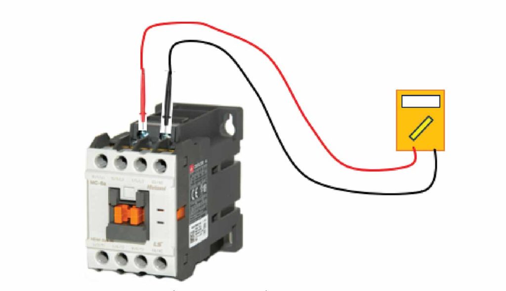
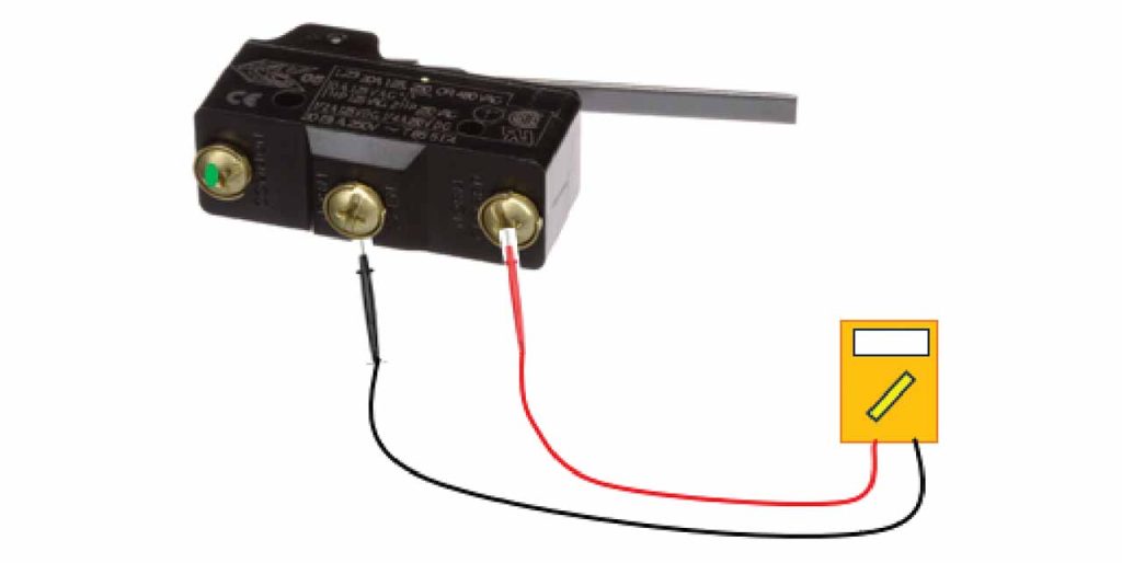
We do a continuity test to check the wire continuity between connectors and to check the healthiness of the fuses. The resistance measurement is done to verify the healthiness of the motor winding and coil of the relay/contactor. We also use it to check the resistance of the NC/NO contacts in relays/contactors, proximity switches, micro switches, etc. See Figure 1 and Figure 2.
Voltage Measurement: The steps for voltage measurements are explained briefly below:
- Change the selector switch to select volts AC (V~), volts DC (V—), milli volts (V—) as desired and plug the black test lead into the COM jack and the red test lead into the V jack.
- Touch the probe tips to the circuit point across a load or power source so that the meter is parallel to the circuit component whose voltage is to be measured.
- The display will show the magnitude of the voltage with the unit of measurement as V AC or V DC mV, V, etc.
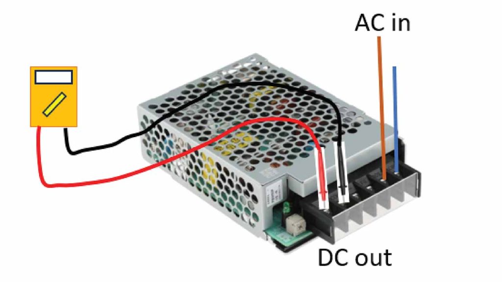
During troubleshooting, we do voltage measurements to check the healthiness of the power supply. For DC voltage readings, polarity is important. Touch the red color test probe to the positive side of the circuit and the black color test probe to the negative side of the circuit or ground. If it is reversed, then a minus sign will appear before the number indicating negative polarity. See Figure 3.
The measurement of current is rarely done using a multimeter while troubleshooting, as the circuit path has to be opened to insert the multimeter in series to complete the current flow. Usually, the clamp meter will be used for such purposes, and when using the clamp meter, there is no need to open the circuit path in which the current needs to be measured.
An insulation tester is used for measuring insulation strength. It is done to ensure the field wires and electrical components connections have enough insulation strength. Most of the time, an insulation tester will be used to check the insulation strength before turning on the power to the newly installed elevator or component.
Apart from that, for some advanced-level troubleshooting, most of the companies provide their own portable proprietary service tool. Using that, we can see the error log, input-output signal status, etc., and are able to change and set some control parameters and activate some test routines, as well.
Troubleshooting
For effective troubleshooting, we need a straight diagram, appropriate diagnostic tools and detailed information for the fault codes and symptoms. Whenever the call center receives an elevator breakdown call, the call center personnel who is attending to the customer call should collect the basic information like the name of the person reporting the call, the elevator number, the address of the elevator location, when it happened, what are its symptoms, etc.
Hence, before going to the site, you need to look through that information when the call is assigned to you. In addition, if you can access the call history for that particular elevator and the respective action taken, then it can give you more insight. If the elevator is connected to the remote monitoring system, then you may be able to get more information remotely before reaching the site. Based on the information obtained, you can prepare the needed spares and tools, etc.
If people are trapped, arrive at the site as early as possible and follow the rescue procedure. Response time for rescuing trapped passengers is usually specified in the maintenance contract, and the elevator service personnel must adhere to that. After completing the rescue operation, you can follow the troubleshooting procedures.
On arriving at the site, contact the person who is in charge of the facility/building and inform them that the elevator is under repair. Collect the required key for accessing the machine room or machinery spaces for troubleshooting. Place proper signs and barricades at the necessary locations. While doing the troubleshooting work, follow the procedure prescribed by your company or from the Elevator Industry Field Employees’ Safety Handbook.
Error Log
Most modern controllers are provided with LED indicators, error displays and the capability to store the error log. Hence, after collecting the required keys, if the elevator controller has a feature of storing the error log, then, first and foremost, go to the controller or to a location where you can download the latest error log. Otherwise, the troubleshooting activities will create more errors and that will overwrite the error related to the actual breakdown call. This can happen because some controllers can store only the latest 20 or 30 errors.
Another issue is with the date and time record of the errors in the error log. If the controller system clock is not in sync with the real-world clock, then the date and time record of the error log also will reflect the same difference. Troubleshooters should be mindful of that difference while creating the hypothesis based on the error log.
With some elevator companies, their controller is capable of not only storing the error with date and time, but they are also capable of capturing some additional information associated with each error like the floor number where the error occurred, at which stage of the speed profile it happened, the status of the elevator shaft switches, direction of travel, etc. All this added information will be helpful in troubleshooting, but it will cost more memory and additional monitoring circuits in the controller. If the troubleshooter receives a detailed manual to understand this additional information, then they can create a mental picture of the error occurring position in the hoistway and focus troubleshooting activities around that area. Sometimes a single fault will create many secondary errors, and the troubleshooter should always look for the first listed primary error from the log to find the relevant cause.
Most of the time, either the error log and/or the status of the LEDs in the control panel and/or the status of the relays/contactors will provide a visual clue on where to start the troubleshooting. Callbacks arising from door operation are very common because the doors are a highly used subsystem and have many moving components with mechanical linkages. Let’s take a closer look at the fault associated with the door system.
Door Related
After retrieving the error log, and the error log shows that there is a door-related issue, then you have to go to that landing where the elevator is stopped and do a visual inspection first. In most passenger elevators, the landing door is passive and the car door is the one driven by the motor. The car door coupler/cam engages with the landing door lock roller in the unlocking zone, and thus opens both doors when the elevator reaches or is going to reach the landing level.
If the elevator is at the landing level and the door is not closing, then the trouble may be due to:
- Door protective device operated
- If the elevator has a mechanical safety edge, then
- It may get stuck at the activated position due to some mechanical issue. This can be verified by visual inspection and by trying to operate it by hands.
- The microswitch contacts of the mechanical safety edge opened permanently or the resistance may be higher. This can be verified by measuring the resistance at the switch terminal. While measuring the resistance value, the value should change from very low to high when the switch is operated by hand. Commonly, these switches are wired using NC contact. Hence, the resistance has to be measured between the COM and NC terminals.
- The electrical cables connecting the microswitch to the car top control station are moving whenever the door closes and opens. Due to that, it may get worn off, opened permanently or the resistance may be higher. This can be verified by measuring the resistance of the cable end at the car top control terminal where it is wired while closing and opening the car door manually.
- If there is a light curtain or light ray, then
- The light curtain/ray healthiness can be verified by looking at the LED status or error display on its control board and by checking it with the manufacturer’s user manual. If the manual is not with you, then troubleshooting can be done by disabling the light curtain/ray and confirming whether the door can close after disabling. If the door is closing, then the problem should be associated with the light curtain/ray.
- The door open button is stuck
- It can be detected by visual inspection and by operating the button.
- Door limit problem
- There may be a door open limit and close limit to inform the door controller that the door has reached the end of its travel. It may be an inductive or optical sensor with an LED light on it to tell the status of the sensor. The trouble can be identified by manually closing and opening the door and visually inspecting the change in the status of the LED, or you have to measure and detect the change in the resistance value if dry contact like proximity switches are used. If the encoder is used, and the problem is with the encoder, then the door system error display should indicate that.
- Doors jammed mechanically
- It may be due to the car door drive chain broken or belt snapped, synchronization rope/belt snapped, door hanger roller dislodged, jammed and not rotating freely or door shoes/guides loosened and stuck. The car door/landing door became misaligned with their respective sill groove due to something banging on the door. In such cases, the door shoes and retainer have to be removed and the alignment issues have to be corrected by straightening the door. Then fix the retainer and guide shoes and check the door operation for freeness and any abnormal noises.
- Door coupler/cam not engaged
- This may be due to alignment issues. The car door coupler/cam must engage the landing door lock roller for proper opening of the landing door. In some installations and some floors, this engagement might be good at the closed position and may be less when the doors are fully opened due to the non-parallelism of landing door headers to car door headers. This has to be adjusted and verified.
- If the elevator has a mechanical safety edge, then
While the door is closing, it intermittently stops, opens and then closes again:
The light curtain and mechanical edge switch contact might open intermittently, or the connecting cable opens intermittently and gives door reopen instructions.
The door operation may become very tight due to some mechanical issues mentioned in the above paragraphs and the required torque exceeded the torque limit set at the door control sub-system.
After the door is fully closed and it is not opening then:
The locking mechanism jammed. It may be due to the clearance between the movable locking mechanism to the stationary hook gap being less. Or it may be due to the mechanical reasons mentioned in the above paragraph.
In certain situations, after doing some visual inspection and to find whether the problem is due to the car door or the landing door, we have to decouple the car door from the landing door by operating the elevator in inspection mode down. Then get into the car top by following the proper car top access procedure*. Standing on the car top, close and open the landing door and car door separately to detect the problem. Thus, depending on the situation, appropriate methodology must be used.
Sometimes the situation may be more complicated in which all the doors are fully closed yet the landing door circuit is open and preventing the elevator from running. In this kind of situation, most of the time the landing door contact at the floor where the car stopped might be having the issue. In some unfortunate cases, landing door contacts on the other floor might be opened due to improper contact pressure adjustment or due to some wire damage issues. To find out which floor it happened, we need to place the car in inspection mode, use the jumper to bypass the landing door* and travel in inspection mode to every floor to check. This checking includes opening the landing door header cover and door lock switch cover to check the voltage in every landing one by one. It will be a time-consuming job. In some worse situations, the wires inside the trunking may get damaged and open-circuited. You might need to open the trunking cover to locate the fault, and for that, you need to know the exact landing/location where the open circuit happened. For an elevator with many landing doors — like 30 or 40 — it is going to be a nightmare.
One of the systematic troubleshooting ways based on your author’s experience is by dividing the landing doors into two equal zones and narrowing the fault to one of these two zones by checking for voltage at the door switch of the mid-floor. After that, consider only the zone with fault and divide that fault zone equally into two by checking the voltage again at its mid-floor. This will narrow down the fault to a smaller number of landings. If we do this successively, we can reach the fault location quickly without as much effort. This can be explained using an example of an elevator system with 20 landings. However, the same concept can be used for elevator systems with a greater number of landings where you can save a lot of time in troubleshooting.
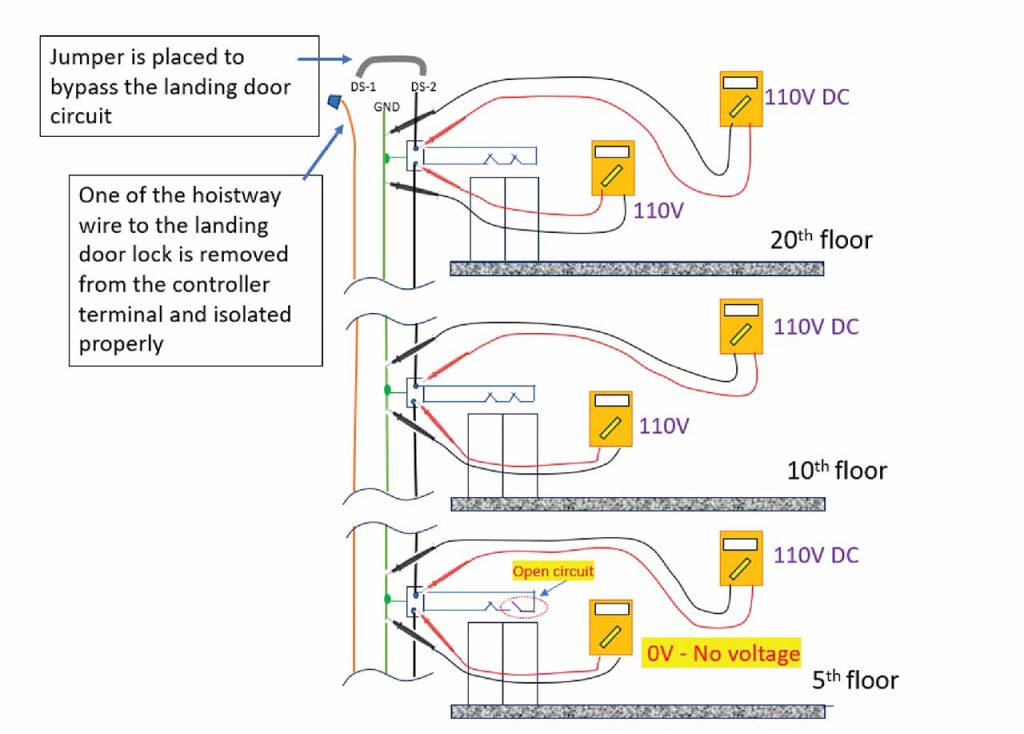
Consider an elevator system serving 20 floors, as shown in Figure 4. All the door contacts are connected in series. The supply from the controller goes down to the bottommost floor through pin 1 of the DS connector (DS-1). It passes through door contacts on every floor and returns to pin 2 of the DS connector (DS-2). The landing door circuit is supplied with 110-V DC and the negative of that DC supply is grounded. Assume there is a landing door lock circuit open issue on the fifth floor, and now let us see the troubleshooting procedure.
After going through the error log, we find that there is an issue with the landing door. The status LED on the controller indicates the same. Then from a straight diagram, we find that the landing door lock connections are in the DS connector located at the controller. The door switch contacts are connected between the pin DS-1 and pin DS-2. When the voltage is measured with a multimeter, there is voltage at DS-1 and no voltage at DS-2. Then we go down to the landing where the elevator is stalled and visually check for the landing door lock switches and their connections. There is no abnormality detected. Now, we need to find the floor where the door circuit opened. For that, we need to get into the car top and move the elevator. It requires jumping the door contacts to move the elevator*.
While bypassing* the landing door contacts by using a jumper at the connector DS, keep the hoistway wire from the top floor landing door locks connected to the connector DS. In our case, it is pin DS-2. The other wire from pin DS-1 has to be disconnected and isolated properly. After that, bring the elevator to the top floor and get into the car top. By using a multimeter, measure the voltage at the top floor door lock connector to ensure there is a voltage of 110 V, as shown in Figure 4.
Move the car in inspection mode to the mid-floor level and, in our case, this is the 10th floor. Measure the voltage at the wires connected to the door lock switches on the 10th floor, as shown in Figure 4. If there is voltage, then it indicates the portion of the lock circuit above the 10th floor is intact and the problem is associated only with the lower portion, i.e., between the 9th floor and ground floor. Hence, the fault zone is the 9th floor and below.
Next, we divide that fault zone into two equal portions and move the car to the mid-floor, i.e., the fifth floor, and do the measurement as before. For our case, we assumed the circuit was opened on the fifth floor. Hence, when we measure the voltage at the two wires connected to the fifth-floor landing door lock connector, we find there will be voltage at one wire and no voltage at the second wire. This indicates there is an open circuit at this floor. Refer to Figure 4.
Replace the wire or properly joint the wire and cover back the lock switch cover and header cover. Go to the machine room or move the car to the controller if it is machine-room-less, and now measure the voltage at the isolated wire carefully. As the open circuit is rectified, there should be voltage at that wire and the meter reading should show that as 110 VDC. Reconnect that wire to DS-1 from where it is removed.
Remove the jumper and try to operate the elevator in inspection mode to confirm the open circuit issue on the landing door is solved. Before opening the elevator for public use, make sure all door contacts and safety switches are functioning as intended.
Conclusion
As technology is developing and electronic device prices are reducing, we can expect a future controller capable of monitoring more control and safety signals and storing more errors. With the use of remote monitoring, we can obtain all the information stored and prepare ourselves with the necessary tools and components before doing the site visit for troubleshooting. However, troubleshooting and repair activities can be done only by a skilled troubleshooter. Hence, the knowledge of elevator operation, understanding the elevator diagram, interpreting the error log and using the troubleshooting tools are very important and should not be ignored. Above all, ensuring everyone’s safety is most important during the process of troubleshooting. Hence, the troubleshooter must adhere to their company-approved procedure or follow the guidance from the latest Elevator Industry Field Employees’ Safety Handbook while doing their task.
*Refer to the latest Elevator Industry Field Employees’ Safety Handbook and follow the necessary safety procedures.
Reference
2020 Elevator Industry Field Employees’ Safety Handbook – ELEVATOR WORLD, National Elevator Industry, Inc.
Learning-Reinforcement Questions
Use the below learning-reinforcement questions to study for the Continuing Education Assessment Exam available online at Elevator Books or on p. 111 of this issue.
- What is the information to be collected before attending a callback?
- What are the various types of elevator drawings and their purpose(s)?
- What are the commonly used diagnostic tools in the elevator industry and their specific use?
- Why is downloading the error log important? Explain the challenges associated with that.
- Briefly explain the procedure involved in troubleshooting the landing door contact/wire open circuit for elevators with a greater number of landings.
Get more of Elevator World. Sign up for our free e-newsletter.
