Emergency Power Operation with Regenerative Drives
Nov 1, 2017

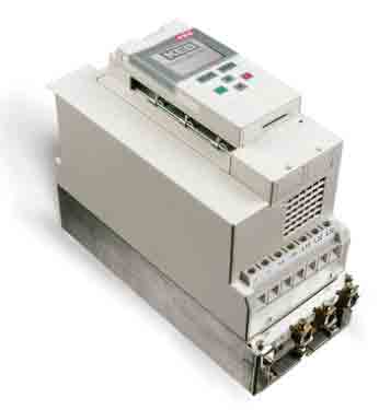
Line regenerative systems, like the KEB R6 regenerative drive (Figure 1), have become popular options in elevator applications over recent years. The increased use of efficient permanent-magnet gearless motors in high-rise buildings and the potential for energy savings makes line regenerative units an attractive option. This is especially true for elevator applications, because the motor is acting as a generator for approximately half of its use.
Before regenerative drives were available, excess regenerated energy from the motor was dissipated across a braking resistor. While this method of energy transfer is simple, all excess energy is turned to heat, which can add to machine-room cooling costs. By taking the excess energy and returning it back to the line, building owners and operators can save money, while making their buildings more energy efficient. Depending on the application, line regenerative systems can pay for themselves in as little as two years.
Regenerative systems are relatively easy to install, and, once set up correctly, operate trouble free. They can be placed right next to the elevator drive in the control panel and work with all other panel components.
Some buildings, such as hospitals, nursing homes and apartment complexes, may require emergency power operation during an outage. Typically, this is accomplished with a backup generator or an uninterruptable power supply (UPS) unit. Regenerative drives can regenerate back to a generator while in emergency power operation, assuming there is sufficient load to consume the energy, but buildings that rely on a UPS unit for emergency power backup pose an opportune situation for regenerative drives.
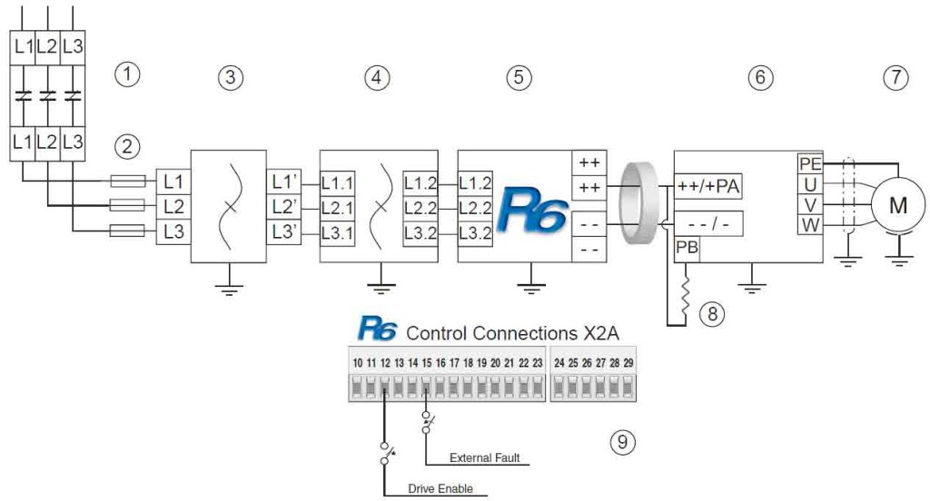
The UPS is, essentially, a large DC battery that provides emergency power to the elevator and controller in the event of a power outage. Regenerating AC power back to an active UPS is not an option, because regenerating back to the DC power supply could cause damage. To safely use a regenerative drive in this type of application, the regenerative drive must be disabled to prevent the flow of AC power back to the UPS unit. Figure 2 shows how this setup can be implemented.
With this configuration, the regenerative drive can be disabled by having a relay contact open the enable signal while the UPS is activated. Additionally, another relay contact can activate an input programmed as an external fault condition to further prevent modulation by the regenerative drive. This setup features dual-level redundancy that ensures the regenerative drive stays in a “passive” state and does not modulate/regenerate back to the UPS unit. The drive still acts as the rectifier, though, even without the enable signal, supplying the drive unit to continue to drive the motor.
The regenerated energy produced by the motor (e.g., empty car up) can be dissipated through a braking resistor on the variable-frequency drive (VFD) unit during UPS operation. Under normal operation, no contactor is needed to deactivate the braking resistor, since the regenerative drive generally begins modulation at a lower DC bus trigger level than the braking transistor activation level; for example, 103% of idle VDC versus 760 VDC. Using this setup ensures the regenerative drive operates safely with the UPS unit while in an emergency power situation.
As building heights continue to increase and with energy efficiency playing a larger role in new construction and modernization projects, line regenerative systems will continue to play an important role. Regenerative drives capable of working with emergency power generators and UPS units give building owners flexibility in choosing the right emergency power backup system for their applications.

Get more of Elevator World. Sign up for our free e-newsletter.


