Energy Code Development, Part Two
May 1, 2014

Part One of this series (ELEVATOR WORLD, April 2014) discussed the history of development of the Code of Practice for Energy Efficiency of Lift and Escalator Installations (CoP) for elevators, escalators and moving walks in Hong Kong. The CoP is now incorporated in the combined volume Code of Practice for Energy Efficiency of Building Services Installation (BEC) published in 2012. Parallel development in Europe was also highlighted.
Part Two will look into some technical details and issues of the CoP and its guidelines, together with a discussion on the benchmarking parameter suggested by your author some 10 years ago and a method to save energy for lifts. For clarity, “CoP” in this article refers to either the previous (2000-2011) editions or the part related to elevators inside the current BEC.
TGs on the CoP[1]
To clarify clauses in the CoP and suggest means of compliance with them, a set of technical guidelines (TGs) were published in 2012 by the Hong Kong Electrical and Mechanical Services Department (EMSD). This article shall first discuss how CoP requirements could be met in a straightforward manner, while those issues which call for special considerations will be addressed later, section by section.
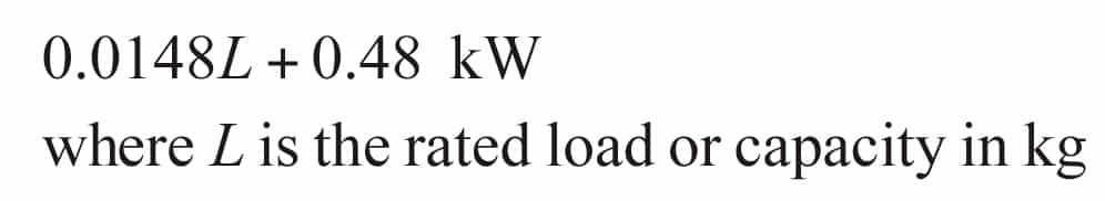
Practically, not all types of fixed vertical- or horizontal-transportation systems inside a building are covered by the CoP or BEC. Some examples are given here, including mechanized vehicle parking systems, goods lifts, stair lifts, rack-and-pinion lifts and backstage lifts. Tables are provided in the CoP to govern the maximum electrical power consumption by traction lift drives and hydraulic lifts (in kW) under different rated capacity (in kg) and rated speed (in mps) when the car is carrying full load and moving upward. For example, the limit of a traction lift with rated capacity between 1350 kg (inclusive) and 1600 kg (exclusive) and rated speed between 4 mps (inclusive) and 5 mps (exclusive) is 49.4 kW. When the rated capacity goes beyond 5000 kg, formulae (instead of prescriptive figures) to show the limit are available. In this case, users are required to perform calculation based on the formulae to arrive at the limit. For example, the equation for a lift with a capacity beyond 5000 kg and with rated speed range between 2 mps (inclusive) and 2.5 mps (exclusive) is given by:
Having said that, some lifts are exempted from such a limit. Examples are super-high-speed lifts with a rated speed not less than 9 mps serving a zone higher than 50 stories (more than 175 m between top and lowest landings), lifts with a rated load at or above 5000 kg and a rated speed of 3 mps or above, firefighters’ lifts, and sky-lobby shuttle lifts serving only two principal stops. For hydraulic lifts, rated speed is not a condition, because they usually run slowly. For example, the maximum electrical power of a hydraulic lift with rated load between 3000 kg (inclusive) and 4000 kg (exclusive) is 92.2 kW.
For escalators, the electrical power consumed by the drive when the escalator is carrying no load and traveling at rated speed is governed by a table under different nominal widths (600, 800 and 1,000 mm), vertical rises (in m) and rated speed. Three more conditions are imposed in terms of the function of an escalator: nonpublic service, public service and heavy duty. For example, the limit of a nonpublic service escalator with a nominal width of 1,000 mm, a vertical rise between 5 mps (inclusive) and 6.5 mps (exclusive), and a speed range between 0.6 mps (inclusive) and 0.75 mps (exclusive) is 3.23 kW. Hong Kong is an extremely densely populated metropolis, where the subway is very congested during rush hours. Heavy-duty escalators are needed to serve subway stations, which are defined in the CoP as follows:
- Operating continuously for a period of not less than 20 hr. a day, seven days a week with an alternating brake load of 100% full load for 1 hr. and at least 50% brake load for the following hour
- Not less than four flat steps at each landing
- Maximum deflection of supporting structure of the escalator not exceeding 1/1,500 of the distance between supports.
- Brake load given by multiplying the number of visible steps by 120 kg.
- Diameter of chain wheel not less than 100 mm.
Moving walks with an inclination up to 6° are governed in terms of the length, width, rated speed, nonpublic service and public service. For example, the maximum allowable electrical power of a nonpublic service passenger conveyor with a width of 1,000 mm, range of length between 16 m (inclusive) and 20 m (exclusive), and range of speed between 0.6 mps (inclusive) and 0.75 mps (exclusive) is 4.703 kW. If the width is 1,000-1,400 mm, the limit is obtained by interpolation of figures found inside the table.
The availability of lift park mode and automatic on/off of lift ventilation and air-conditioning during idling are straightforward, and do not need to be discussed here. For the air-conditioner, the CoP requires that once it is turned off, it cannot immediately be turned on, even when a passenger walks into the lift car.
It is known that in some cities, the in-car illumination is also turned off when the lift is idle. Your author does not support such an idea, because the energy consumption of the lamps, (normally few tens of Watts only) inside the car is usually negligible, compared with the total idle consumption of the whole lift. Furthermore, most installations are still of the discharged type (fluorescent tubes, compact fluorescent lamps, etc.), which are not suitable for being turned on and off frequently due to their lifespan being inversely proportional to the number of on/off cycles. Nonetheless, LED lamps are getting more and more popular. If they are ever widely applied to in-car illumination, that would be another consideration.
The final item to be discussed before we move on to special issues is the provision of metering facilities. Electrical parameters, including voltages, currents, total power factor, total harmonic distortion, energy consumption and maximum demand (in kVA) of lifts, escalators and moving walks, are to be measured in accordance with the CoP. A networked permanent meter equipped with each installation is perfect for this, as the owner and maintenance contractor can continuously monitor the lift performance remotely. But, if that is too costly, the provision for measurement is allowable. An electrical cubicle or junction box can be equipped on lifts to facilitate the ready connection and subsequent removal of a metering device. Such connection/removal actions must not affect the normal operation of the lift by any stoppage or disruption. For escalators and moving walks, landing plates or inspection doors have to be opened for connection/removal. Safety switches are required to stop the operation of escalators and moving walks once these plates or doors are opened.
Total Harmonic Distortion (THD)
Electrical power quality is drawing top concern by the industry nowadays. The topic discussed is usually the quality of the supply voltage to a system or a device, which can be described by a set of parameters,[2 & 3] including:
- Voltage fluctuations (swell or sag)
- Voltage dips
- Voltage imbalance
- Power frequency variations
- Induced low-frequency voltages
- DC components in AC networks
- Radiated low-frequency phenomena
- Harmonics and inter-harmonics
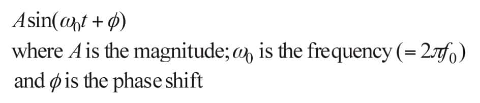
International standards[4 & 5] are available on power quality. While the concern is on voltage, readers may have heard much more about current harmonics. Why? Half a century ago, all electrical appliances (such as motors and incandescent lamps) were either resistive, inductive or capacitive in nature. These devices are considered passive, meaning that the current waveforms drawn by them are of the same shape as the voltage waveforms applied to them. AC voltage is usually either 50 or 60 Hz in frequency (f0) and generated with an intrinsically sinusoidal shape from the power plant. “Sinusoidal” refers to a waveform that can be uniquely described by the following equation:
Electronic devices were becoming very popular in the late 1960s. Nowadays, it is quite difficult (though not impossible) to find a device that is still purely resistive, inductive or capacitive. Electronic (solid-state) devices are active in nature, meaning that their current and voltage waveforms are significantly different (no longer sinusoidal, as shown in Figure 1). To analyze its awkward shape, we can use the Fourier equation, which tells us that any periodic waveform, f(t), of any shape can be represented by a combination of an infinite number of sinusoidal waveforms:
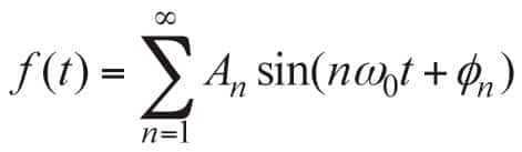
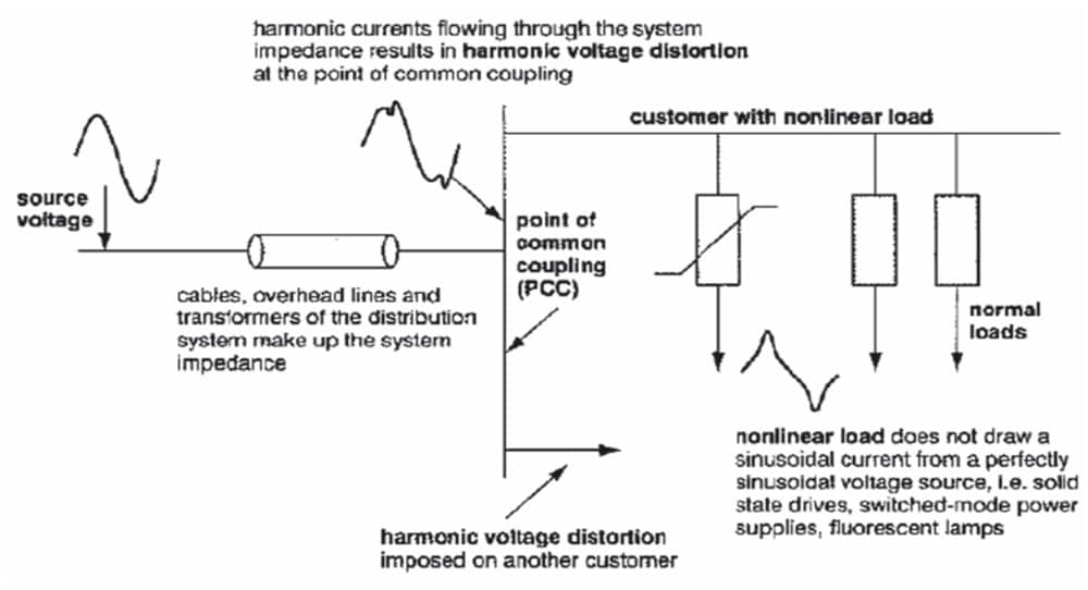
Here, n is called the “harmonic number,” and the fundamental refers to n = 1 (i.e., generally 50 or 60 Hz). For each n, there is a magnitude An and a corresponding phase shift øn. Here, A could be either voltage or current. In other words, the existence of higher-frequency components is used to describe waveforms that are not purely sinusoidal. While the concern is on voltage, the problem involves current. The source voltage from the generating plant is usually sinusoidal, but power has to be transmitted to the user through cables that constitute both the transmission and distribution networks. Such cables have resistance, inductance and capacitance. The effect of inductance increases as the frequency increases. Current drawn by an electronic device, if possessing harmonics, results in the existence of voltage drops across the cables at the respective higher frequencies. Again using the Fourier equation, the resultant voltage waveform at the point of common coupling (such as the supply point of a building close to the device) is no longer sinusoidal (Figure 2). In other words, current with substantial harmonics drawn by an active device can lead to a poor voltage waveform at the supply point, which is harmful to all other devices connected to a common coupling point. That is why current harmonics have to be mitigated.
THD is one useful parameter to by which describe the seriousness of harmonic distortion, which is applicable to both voltage and current. Their definitions, also adopted in the BEC, are as follows:
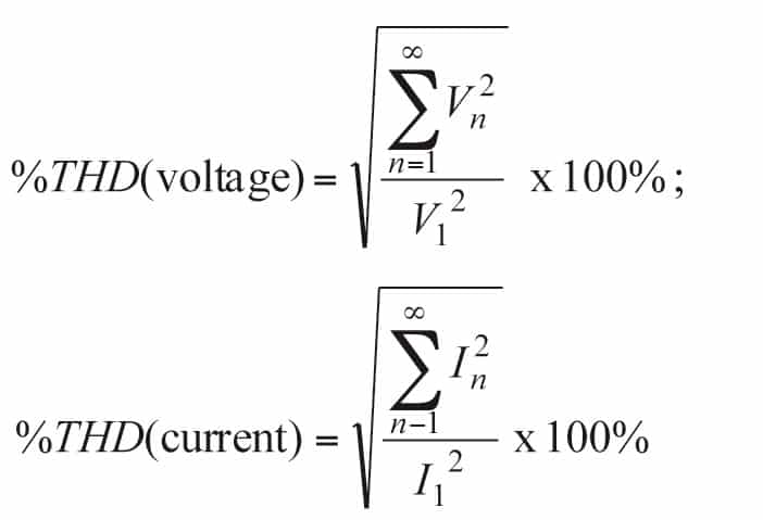
Here, V1 and I1 are called fundamentals. In the CoP, tables give limits of THD for lifts, escalators and moving walks. For example, if the fundamental current of a lift, carrying full load and traveling upward, is between 40 A (inclusive) and 80 A (exclusive), the THD must not go beyond 35%. Although the two equations have been taught in almost all Electrical Engineering schools around the world, I can assure my readers that they are impractical. No instrument ever constructed on Earth can measure a voltage or current to give an accurate value of THD based on the two equations. The trouble comes with the term infinity. Therefore, in the TG, THD is only measurable up to 31st harmonics (n = 31).
Total Power Factor
Total Power Factor (TPF) is the ratio of the active power of the fundamental (in kW) to the apparent power that contains the fundamental and all harmonic components (in kVA). The “two-wattmeter method” is a standard technique by which to measure the total active power of any three-phase, three-wired system. Wattmeter 1 measures the current of line 1, and the voltage between lines 1 and 2. Wattmeter 2 measures the current of line 3 and the voltage between lines 3 and 2. The active power values of the two wattmeters, when summed, give the total active power. Sometimes (in particular, when the three phases are not balanced), one wattmeter may give a large positive value, while the other one may give a low or even negative value. The sum is always the correct answer, and that is the beauty of this method. Any line could be any phase, irrespective of the phase sequence.
There are two problems with existing lift drives. First, very often, there are only three wires connected to the drive from the three phases (no neutral wire). Second, it is very difficult to get a totally balanced supply to the drive (i.e., not all three line voltages and currents are equal). Fortunately, the “two-wattmeter method” is accurate enough, irrespective of voltage balancing or currents. As for apparent power, this has traditionally been defined in a three-phase system by the following equation:
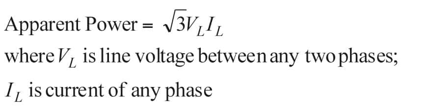
If voltages and currents are not balanced, which two phases should be selected for line voltage, and which phase should be selected for line current? A solution is at least offered in the TG, although the academic background is not strong enough. The average of three line voltages is treated as VL, and the average of three line currents is treated as IL.
One final TPF point to mention is that it is possible to measure the TPF for traction and hydraulic lifts onsite, but impossible for escalators and moving walks, because the condition imposed is that the escalator or conveyor must be driving brake (full) load when the TPF is measured. It is possible to put dummy loads inside an elevator car but not on escalator steps. If dummy loads equal to the brake load are put on all visible steps of an escalator, it cannot start to run upward. If it is allowed to run downward, the dummy loads will shatter on the lower landing well before any measurement can be completed. After all, the escalator is not driving a full load if allowed to move downward with a dummy load on every visible step. So, the TG guides designers or consultants to estimate the TPF by theoretical computation, while real experiments could only be conducted in a factory (not onsite).
Benchmarking Parameter of Elevator Energy Performance
By going through the maximum allowable power consumption in the CoP of BEC of Hong Kong, as well as the specific energy consumed during a reference run of empty lift car per Europe’s VDI 4707 and ISO 25745, readers may conclude that at present, almost all energy codes available are focusing on the energy efficiency of the lift drives alone. Perhaps it is not well known that the intelligent supervisory controller of a lift system is actually responsible for overall energy efficiency. In the building-automation industry, it is commonly known as “good housekeeping.” A discussion on this issue is beyond the scope of this article, but I would like to quote the following analogy.
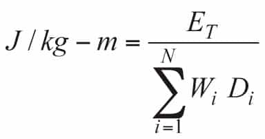
For a room that only utilized 3 hr. a day, which approach consumes more energy: A 90%-efficient lamp operating 24 hr. a day or an 87%-efficient lamp operating only 3 hr.? The author has been promoting the inclusion of supervisory control into the consideration of energy efficiency for almost a decade, but the problem is the lack of a universally acceptable parameter that can take care of both the lift drives and dispatcher. A benchmarking parameter called J/kg – m was proposed by your author some ten years ago.[6 & 7] Coincidentally, it apparently bears the same dimension as the specific running energy of VDI 4707, but the concept is totally different. The latter figure is obtained by measuring the energy consumed by an empty lift running one reference cycle.
J/kg – m (also mentioned in CIBSE Guide D: Transportation Systems in Buildings 2010) deals with daily operation when the lift car is under normal load. The parameter can reflect the energy performance of a lift or bank of lifts, accounting for both the power consumption of the motor drive, as well as the intelligence of the supervisory controls. J/kg – m is now recommended in the TG as an emerging good engineering practice. Three parameters are needed to evaluate J/kg – m: total energy (ET) consumed within a fixed period of time (T), car load (W) and distance traveled (D). During T, an N number of brake-to-brake journeys is made by the lift car, each journey carrying W running D, irrespective of direction of travel. A brake-to-brake journey starts when the brake is released and ends when the brake is applied again.
Some previous measurements indicated that a very energy-efficient elevator and its corresponding intelligent supervisory control could achieve 30 J/kg – m (the lower, the better). Readers are highly recommended to implement this parameter on their installations so a substantial database can be built. Throughout a 24-hr. day, J/kg – m could rise to a huge value during off-peak times, because a certain amount of energy has to be consumed while the traffic is extremely low (small W and small D). Therefore, the average of a series of running windows, (say, with T = 2 hr.) and a running incremental interval (say, 15 min.) will give a fair result.
Counterweight Adjustment Method
A method to save energy was developed and tested with success based on the proposed parameter.[7 & 9] At present, the counterweight setting is purely based on safety considerations, where good traction is available under both no- and full-load conditions. Usually, this setting is 50% of the rated capacity of the lift car. The method suggested allows a readjustment of the counterweight setting, within a safe range (say, 40-60%, depending on the type of roping arrangement).
A series of experiments is first conducted to develop a database of energy consumption of a particular lift in terms of load (0/20/40/60/80/100%), zone (low/middle/high rise), direction (up/down), distance of travel (one/two. . . floor jump/full travel) and counterweight setting (40/45/50/55/60%).
When the lift is under normal operation, data of every brake-to-brake journey, including time, car load, direction, distance travel and zone, are recorded by a central server. For, say, every two weeks, a computer simulation is performed to find the optimal counterweight setting for the past two weeks that corresponds to minimum energy consumption. If the traffic pattern remains more or less the same, that optimal counterweight setting could ensure the lowest energy consumption of the lift for the coming two weeks. After a year, the total energy profile of the particular lift is known, and the setting could be more intelligent, even with accurate prediction.
Conclusion
The history of energy-code development related to lifts and escalators in Hong Kong and their parallel development in Europe have been introduced in this series. Technical details and issues within the Hong Kong energy code were also discussed. A generic benchmarking parameter to compare the energy performance of different types of elevators, irrespective of their rise, load and speed, was proposed and explained. Statistically, a fair indication of whether a particular lift or group of lifts is energy efficient can be provided by taking care of both the drives and supervisory controls. A technique to save energy for lifts by readjustment of the counterweight setting is also mentioned.
At present, energy codes are still not widely adopted worldwide (as opposed to safety codes). The author hopes these articles can help engineers draft or improve energy codes, or implement them in a better way by giving reference to the experiences from Hong Kong and Europe.
References
[1] EMSD, Technical Guidelines on Code of Practice for Energy Efficiency of Building Services Installation, 2012.
[2] Dugan R.C., McGranaghan M.F., Santoso S. and Beaty H.W., Electrical Power Systems Quality, 3rd Edition, McGraw-Hill Professional, 2012.
[3] Fuchs E.F. and Masoum M.A.A., Power Quality in Power Systems and Electrical Machines, Elsevier Academic Press, Boston, 2008.
[4] IEEE, Recommended Practices and Requirements for Harmonic Control in Electric Power Systems, Standard 591, 1992.
[5] IEC, Electromagnetic Compatibility – Part 3-2: Limits for Harmonic Current Emissions, 2001.
[6] So A., Cheng G., Suen W. and Leung A., “Elevator Performance Evaluation in Two Numbers,” ELEVATOR WORLD, Vol. LIII, No. 1, January 2005, p. 102-105.
[7] Lam D.C.M., So A.T.P. and Ng T.K. “Energy Conservation Solutions for Lifts and Escalators of Hong Kong Housing Authority,” Elevator Technology 16: Proceedings ELEVCON 2006, IAEE, Helsinki, June 2006, p. 190-199.
[8] Chartered Institution of Building Services Engineers (CIBSE), CIBSE Guide D: Transportation Systems in Buildings 2010, p. 13-5.
[9] So, A. and Wong, C.T.C., “Implementation of Counterweight Adjustment to Achieve Energy Savings”, Elevator Technology 19: Proceedings of ELEVCON 2012, IAEE, Miami, May 2012, p. 185-192.

Get more of Elevator World. Sign up for our free e-newsletter.


