A look at the importance of both in vertical transportation
While auditing elevators, I came across many situations where the positioning of equipment and the clearance around it were not sufficient enough to work freely during repair or maintenance. I thought it fit to share my experience with elevator industry personnel, so that they do not face any problems during maintenance or repair work. A few of the actual site conditions are studied in detail and are reported here with photographs.
In principle, every elevator installation needs to be carried out as per the layout drawing. The layout drawing specifies the position of various parts and required clearances around them.
Clearances are maintained, keeping in mind the Indian Standards (IS) specifications and lift rules.
Clearances play a very important role in the operation of a particular assembly. We need to understand the importance of various clearances required during elevator installations.
Let me explain some of the important assemblies and required clearances for their installation.
1. Machine Unit
While installing the machine unit, we need to provide clearances around it as per lift rules. This will ensure sufficient working space, which may be required during any repair or replacement work post-installation.
In general, we need to maintain 600 mm of free space around the machine.
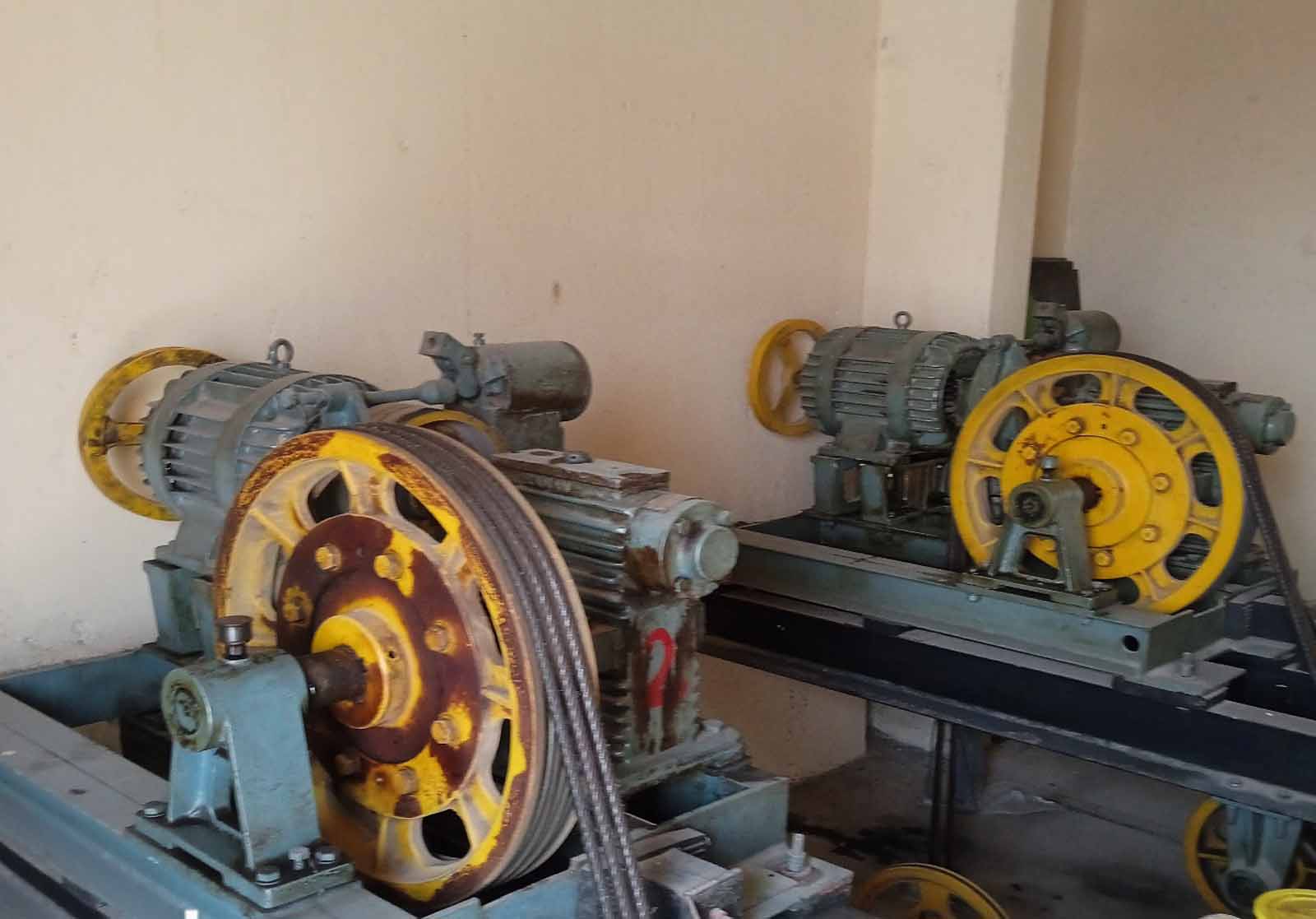
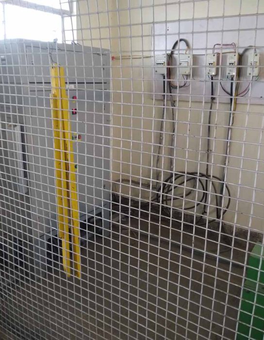
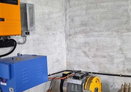
Refer to the actual site photo of a machine unit (Image 1), where the clearance between the flywheel end of the machine unit and the machine room wall is hardly 50 mm. In such a condition, how can one remove the motor, move the elevator through hand-winding during an emergency trapped situation or even remove the rotor unit?
As per the lift rules, the clear free distance between the machine unit and the wall or any other equipment needs to be not less than 600 mm.
Even in the case of a machine-room-less (MRL) elevator, we must take the proper approach to the machine unit inside the shaft and proper working space around the machine unit.
Study the actual photographs and think of situations like:
- Hand-winding during emergencies
- Removal of hoist motor
- Replacement of coupling rubbers
- Working around the machine unit in an MRL system
- Approach to the machine in an MRL system
2. Top/Bottom Clearance
The top and bottom clearance is decided based on the elevator speed. In case of overrun, the cabin body should not hit the machine room slab bottom part or the lowest structure below the machine room slab.
The height of the counterweight in the pit is maintained in such a way that in case of an overshot of the cabin, the counterweight should rest on the counterweight spring buffer before the cabin touches the machine room slab. In this context, we will study the top and bottom clearance in the elevator.
As per lift rules and IS recommendations, the distance between the counterweight spring top plate and the counterweight frame bottom plate should not exceed 900 mm. Similarly, the distance between the car buffer plate and the cabin bottom frame should not be more than 600 mm. With this, the cabin will not hit the machine room bottom slab in case of overshoot. On the other hand, the counterweight frame will not hit the machine room slab in case the cabin rests on the spring buffer.
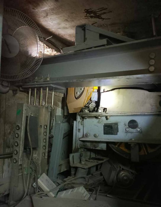
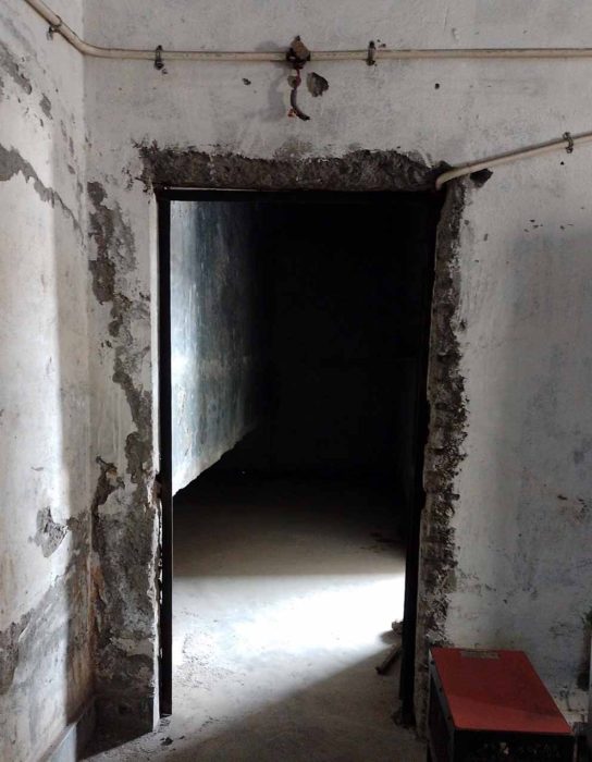
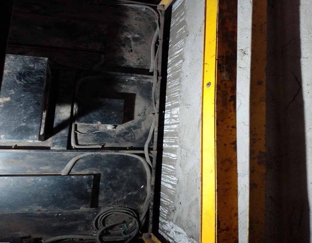
Even after having all the rules, inspections and audits in place, we came across accidents where the cabin moved up and hit the machine room bottom slab. The actual accident site photos (Image 2) show what happens when the rules are not followed properly. The lesson to learn is that, while designing, installing or maintaining any elevator, we must follow the prescribed rules and safety norms.
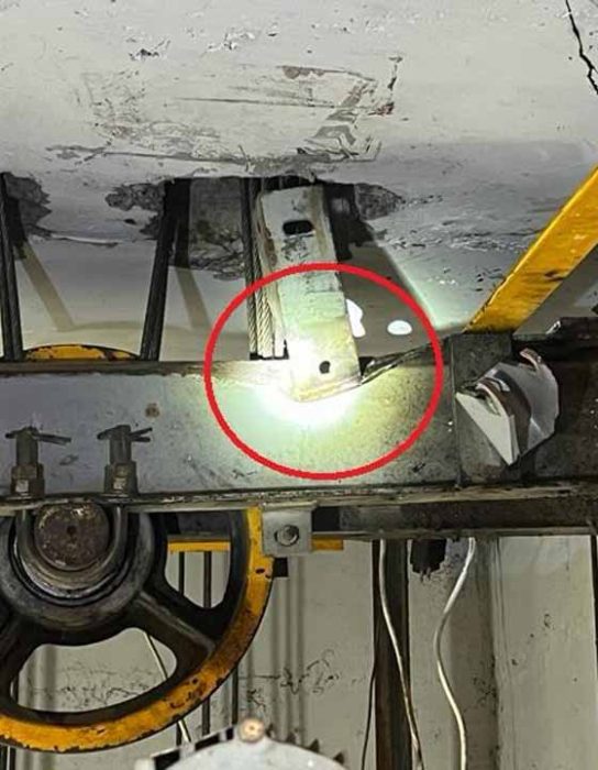
Image 3 shows the result of our carelessness. If the top clearance and bottom clearance were maintained as prescribed in rules, this could have been avoided.
3. Controller Clearance
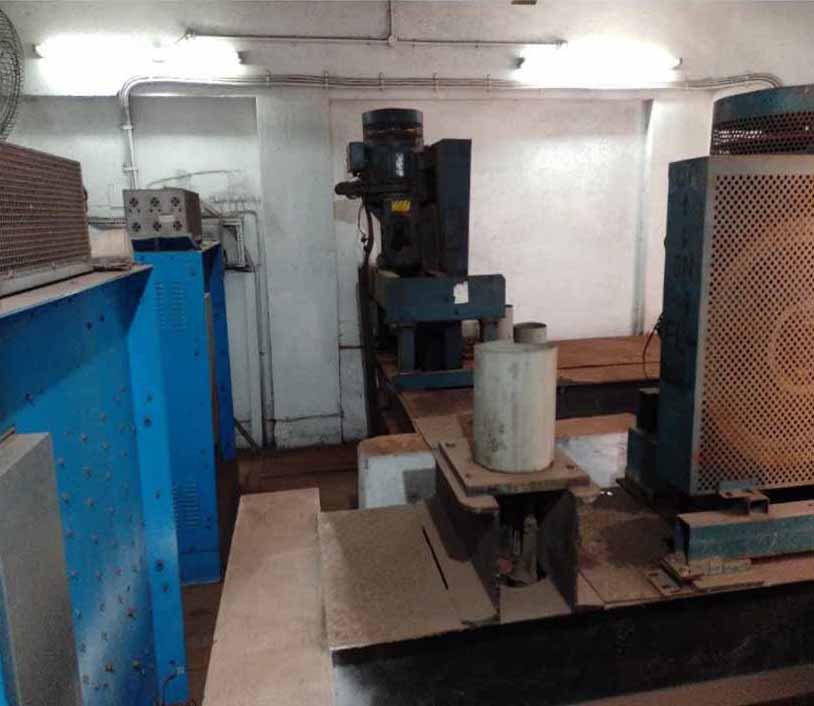
While installing the controller in the machine room, we must ensure that enough space is provided around the control cabinet so the technician can freely work with the control from any side. This needs to be maintained at 600 mm on the front and back side of the control panel.
In addition, if two controllers are placed side by side in one machine room, proper distance must be maintained between them.
Study Image 4 and think of the situations where you need to check the control panel from the back side or replace some controller components.
4. Main Switch Positioning
The main switch or any other electrical switch needs to be installed beside the entrance door so one can approach the switch immediately upon entering the machine room. In addition, the approach to the main switch must be free of any obstructions/hurdles.
Just study Image 5 where, at one site, the main switch is installed on the opposite side of the entrance. At another site, we noticed that the main switch is installed far away from the entrance. Even the light switch is not near the entrance door.
Study Image 6 and think of the situations where you need to suddenly switch off the system during any emergency. Even while entering the machine room, you need to switch on the machine room lights and the elevator main switch. How is it possible?
5. Gap Between the Cabin Back Panel and Back Side Wall
At one of the sites, it was found that the gap was hardly 25 mm between the cabin panel and wall. Just think of the situation where you need to go replace the back cabin panel to install a handrail or tight cabin bolts or carry out any such activity.
Study Image 7 and think of a situation where you need to install/remove the handrail, need to fix the mirror and tighten the panel joints.
It seems that the safety aspects are neglected at all levels including drawing preparation, installation, internal quality check and lift certification. We need to check first whether the position and distances are correctly mentioned in the layout drawing. Even while installing, we must be mindful of such requirements and understand service issues.
Get more of Elevator World. Sign up for our free e-newsletter.
