
Numerical analysis of subsystems and passenger loads against the escalator truss in accordance with EN 115 is explained and demonstrated.
Escalator trusses are manufactured for the installation of subsystems, such as the motor, gearbox and control panel. Every nonstandard truss deflection may affect other devices and decrease the life of parts and safety. Nonstandard deflection can affect the tracking system and cause unsmooth and inconvenient operation. In this article, deflection and tension in the truss will be calculated in accordance with EN 115, supposing subsystem and passenger loads.
Introduction
A lot of mechanical and electrical elements are installed in escalators, making them complicated electromechanical devices. Their motors and gearboxes are the main parts that produce power to move their sprockets on main shafts: this rotation will cause the step chains and steps to operate on the tracks. Control panels and other safety devices control safe operation.
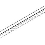
One major component in every mechanical system is structure. In complicated designs (such as for airplanes or spacecraft), structure is very important. The escalator truss, as the main structure, must be designed in accordance with the standards-specified criteria.
Nathan Ames, a patent solicitor from Saugus, Massachusetts, is credited with patenting the first “escalator” in 1859. He noted that steps could be upholstered or made of wood and suggested that the units might benefit the infirm within a household. In 1889, Leamon Souder successfully patented the “stairway,” an escalator-type device that featured a “series of steps and links joined.” In 1892, Jesse W. Reno patented the “Endless Conveyor or Elevator,” which he called the “inclined elevator.”[1] In 2004, Osman Altuğ Akyol described strength analysis of the escalator frame using the finite-element method and calculation of the drive system.[2]. In 2016, K. Bhaskar and B. Subbarayudu studied truss material and static analysis.[3]
Escalator Technical Specifications
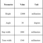
In this study, a typical escalator and its technical specifications have been considered as the main parameters for truss design and analysis (Table 1). The parameters are defined as:
- Height: vertical distance between upper and lower floor by which the truss is manufactured
- Angle (of inclination): maximum angle between step and horizontal line. The truss is manufactured in accordance with this inclined area.
- Step width: width of moving steps, upon which the load of passengers is exerted on it and transferred to the truss
- Truss width: width of manufactured truss, dependent on step width
- Truss length: length of manufactured truss, dependent on angle and height.
In accordance with EN 115, the truss must be compliant with the deflection formula. The truss bears two types of load. The first is the load exerted by subsystems, such as the motor and handrail. The second is the distributed load exerted by passengers. Subsystems’ loads are as listed in Table 2 (both concentrated and distributed loads).
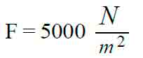
Distributed load due to passengers, in accordance with EN 115 guidelines for distributed load is:[5]
Loading area is calculated as:
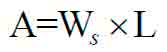
in which Ws is step width, and L is truss length. In accordance with Table 2, every force with a specific row number will be shown in diagrams (Figures 1 and 2).
Finite Element Model
After truss modeling, beam and shell elements are assigned in ABAQUS/6.10. Beam elements are considered angle steel, and shell elements are considered as soffit plates. Soffit plate thickness is assumed to be 3 mm. Nodes and elements are shown in Figure 3.
Constraints
Every escalator truss must have a minimum of two supports defined to bear loads. In this typical study, another support in the middle is designed as an intermediate support. The truss has no displacement in supports area in z direction.
Displacement and Tension Analysis
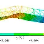
After meshing and analysis in accordance with the displacement contour, the maximum deflection is 8.47 mm.
Tension analysis and results are divided to the areas of the soffit plates and angle steel. The tension contour maximum tension occurred in the angle steel, which is 102.08 MPa.
Result
Structure Displacement
In accordance with EN 115, structure displacement must be:
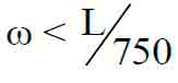
in which ω is maximum deflection, and L is truss length. Thus:
ω = 8.47
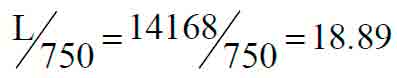
8.47 < 18.89
This satisfies compatibility.
As the metal used for the structure is ST37, the safety factor in the tension analysis is calculated as:
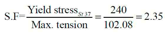
This satisfies compatibility.
Conclusion
With one intermediate support, the standard technical requirement is satisfied. Critical points in the truss are defined, and it is better reinforced. This method can be applied to every other question of whether extra support is needed. In future studies, this method can be developed into user-friendly software and applied to shorten the truss, extend the truss and design a huge reinforced truss without intermediate support in specialized projects.
-
- Figure 1: Whole escalator force diagram
-

- Figure 2: Upper module force diagram
-

- Figure 3: Beam and shell element
-

- Figure 4: Displacement contour
-
- Figure 5: Tension contour
-
- Table 1: Technical specifications of a typical escalator[4]
-
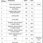
- Table 2: Subsystem loads[4]
References
[1] George R. Strakosch and Robert S. Caporale. The Vertical Transportation Handbook, Fourth Edition. John Wiley and Sons (2010).
[2] Osman Altuğ Akyol. Strength Analysis of the Frame of the Escalator Using the Finite Element Method and Calculation of the Drive System. The Graduate School of Natural and Applied Sciences (Sept. 2004).
[3] K. Bhaskar and B. Subbarayudu. “Design and Analysis of Escalator Frame,” International Journal of Advanced Scientific Technologies in Engineering and Management Sciences, Volume 2, Issue 9 (Sept. 2016).
[4] Canny Group Co., Ltd. “Technical Report” (2007).
[5] European Committee for Standardization. EN 115-1:2008: “Safety of Escalators and Moving Walks — Part 1: Construction and Installation” (2008).
Get more of Elevator World. Sign up for our free e-newsletter.
![]()


![]()