Fastest Elevator – A Competition in High Technology
Sep 1, 2014
How the speed and height races in the elevator and construction industries have contributed to the solutions of many problems and predetermined the mile-high building.
During the past two decades, we have seen a growing trend in the construction of ultra-high-rise buildings served by super- or even ultra-high-speed elevators. An overview of these buildings and elevators is first presented, followed by a review on the high technologies associated with the implementation of such installations. It is apparently an open competition between elevator manufacturers to attempt the technology climax.
Why Speed Elevates
Over the past century, it has been a global trend that people tend to move to work and live in cities that continue to grow to become metropolitan areas where there is one or more urban core(s), often called a central business district(s) (CBD). The signatures of these CBDs are dense populations, costly real estate and good logistic systems, but always with the issue of serious traffic congestion during rush hours. As the CBD is overcrowded with people, it is, of course, overcrowded with buildings. The only way to increase the population of a CBD, at least during office hours, is to construct ultra-high-rise buildings.
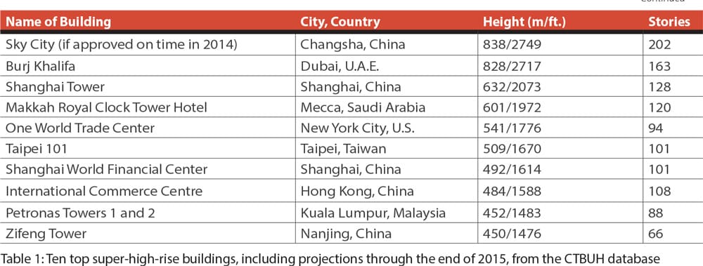
From Table 1, it is apparent that faster elevators are needed to serve these buildings, as the units travel longer distances, both in terms of shuttle express (having a couple of stops) and zone-serving elevators. As technical professionals, we need to be a bit more quantitative to understand the reason. Thus, let us revisit the famous equation of round-trip time (RTT) of a typical elevator journey during the morning up peak.[1]

An efficient elevator supervisory control system strives to reduce RTT in order to increase handling capacity (HC), because they are inversely proportional. In the equation, P refers to the number of passengers inside the car, and tp refers to the average time for each passenger to walk into or out of the car. P depends on the car size, which is very often limited by the floor area of the building. ts refers to the stopping time with respect to every floor, consisting of the performance time (T) minus time to transit two adjacent stories under rated speed (tv). H refers to the highest reversal story of the round trip (only a statistical figure), which increases in value along with building height. S is the expected number of stops during the round trip, which is uncontrollable unless the hall/destination call-allocation control is called upon to group passengers to the same destination together so as to significantly reduce S. Therefore, one effective way to minimize RTT is to make tv smaller, because in the equation, 2H is much larger than (S + 1). By definition, tv = df/v, where df is the inter-story distance, and v is the rated speed of the elevator. A larger v (i.e., higher speed) implies a lower tv.
The speed records found in Table 2 have already been broken by the construction of the Shanghai Tower (ELEVATOR WORLD, July 2013). Three of the 106 elevators serving the tower have a rated speed of 1,080 mpm during an upward journey but only 600 mpm during a downward journey. Additionally, some of the fastest double-deck elevators in the world, at a rated speed of 600 mpm, were installed there.
On April 21, Hitachi announced that the world’s fastest elevators with a speed of 1,200 mpm will be installed in the 530-m-tall Guangzhou CTF Finance Centre (EW, June 2014). Such units will travel a shaft height of 440 m from the first to the 95th floor in approximately 43 s. However, they are only two out of a total 95 elevators serving the whole building. An ultra-high-rise building is always a landmark of a megacity, as well as a grand show by the building owner; naturally, the installation of ultra-high-speed elevators for such a building is also a demonstration of the technology level of the manufacturer. This article shall review technologies developed to facilitate such super- or ultra-high-speed elevators.
Drive
Like the engine of an automobile, the prime mover of an elevator is the drive/traction machine. The 1,010-mpm elevators in Taipei 101 are each driven by a 650-kW permanent-magnet, synchronous-machine (PMSM) motor with two sets of stator windings and a large-capacity converter/inverter, which can bear a maximum shaft load of 77 T.[5] The drive/traction machine to be installed for the 1,200 mpm elevator serving the Guangzhou CTF Finance Centre is also of the PMSM type. Traditional traction machines are of the induction type, but for ultra-high-speed elevators, the passive squirrel-cage windings inside the rotor have to be replaced by surface-mounted permanent magnets, while the windings of the stator resemble more of a standard three-phase induction motor. In this case, the magnetic field associated with the rotor is intrinsic; it is not produced by the stator magnetic field and, thus, has much higher efficiency due to less copper loss at the rotor and an enhanced magnetic field strength from the rotor. Its torque is, therefore, much larger. More importantly, both the power-to-weight and torque-to-current ratios are significantly increased, making PMSM drives suitable for such applications. Also, PMSM drives can operate on a wider speed range with constant torque, something required by elevators. The reason a super-high-powered motor is needed for an ultra-high-speed elevator is due to the following simplified equations:

Here, J is the moment of inertia of the whole system being driven; ω is the rotating speed of the rotor in the unit of rad/s., which is proportional to the car speed; TD is the driving torque provided by the stator; TL is the load torque, which includes aerodynamic resistance; and P is the power dissipated to drive the rotor, which is almost equivalent to the power consumed by the motor as a whole. During operation, TD is almost constant; therefore, P is proportional to ω. Thus, under acceleration, the faster the car, the higher the power consumption by the motor. Under rated-speed operation, the power consumed is much lower, because TD is only equal to TL, though P is still speed dependent.
Aerodynamics and Car Shape
Similar to trains moving at high speeds in tunnels, the same problem with aerodynamics has to be tackled in elevator engineering, but the issue is sometimes more serious due to the relatively smaller ratio of hoistway area to car area. The aerodynamic noise and excessive vibration (particularly within the human-sensitive range of 1-80 Hz) due to the drag force exerted on the ultra-high-speed ascending car, have to be mitigated. In the early 1990s, two Japanese research teams conducted preliminary experimental works to determine the best car shape.[4 & 8] They studied the mechanical noise generated at the contact between the car and guide rails, as well as that due to airflow around the car inside a narrow shaft. It was found that aerodynamic noise became greater in proportion to the fifth through sixth power of the airspeed around the car; thus, the higher the car speed, the higher the noise level. They were using a wind-tunnel approach, in which the car was stationary in moving air.
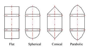
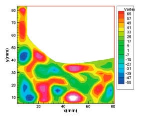
Your author and research partners conducted a series of real simulations of moving cars using four cylindrical car models with different shapes of tops and bottoms (flat, spherical, conical and parabolic) moving in a cylindrical shaft around 10 m high with speeds up to 780 mpm (Figure 1). Two block ratios (cross-sectional area of car to shaft-area ratio) and different open ratios (area of openings at the two terminals of the shaft to the shaft-area ratio) were tested.[7] The digital particle image velocimetry (DPIV) velocity and pressure estimation system, which is a planar optical-measurement technique measuring the velocity of seeded particles in air (around 1-50 microns in size) over a plane using a charge-coupled device camera was adopted (Figure 2). The air pressure and velocity distribution in front of the car were measured, and the conclusion excluded flat top and bottom designs for such ultra-high-speed operation. The priority of favor is parabolic, followed by spherical and conical. The roof and bottom of the aerodynamic capsule used in Taipei 101 is also partially parabolic in shape,[5] but the car needed to be rectangular to fit the rectangular shaft.
Besides the external consideration, in-car atmospheric pressure and noise control is of utmost importance for passenger comfort. There is an atmospheric-pressure difference of 48 hPa between ground level and the 89th floor of Taipei 101. The car is airtight, and all gaps are sealed with an in-car barometer under continuous control by a blower.[6] During an upward journey, the in-car pressure change is limited to 1.26 hPa/s. with atmospheric control, versus 2 hPa/s without it. A rapid change in pressure during a high-speed elevator journey brings discomfort to the passengers in terms of ear blocking and muffling sound. A method to measure the displacement and motion of the tympanic membrane of passengers was developed by using the shape from shading method.[2] It was concluded that the eardrum usually bulges inward during descent, and the limit of the average displacement of the eardrum is approximately 2 mm when the blocked-ear sensation becomes worst. Finally, there is still a hissing sound due to airflow or the blower under a high speed around the car transmitted to the interior through the ventilation channel. Noise cancellation is needed to keep the car quiet.
Mechanical Vibration
There are two types of mechanical vibration: vertical and horizontal. Elevator vertical vibration is normally due to lateral vibration and elastic movement during acceleration and deceleration of the hoisting ropes.[5] A servo system and ripple canceller have been introduced to counteract the vibration due to rope elasticity and the ripple components of motor torque. The installation of suppressors against rope deflection and the car-speed reduction mechanism during building sway can improve vibration due to the lateral movement of hoisting ropes. Besides hoisting ropes, vibration of the compensating ropes is also a concern for ultra-high-speed elevator applications, because the low-frequency sway of the building structure can excite the compensating ropes. The risk becomes high when there is a resonance between the natural frequency of compensating ropes and that of the building during an earthquake or windy weather, resulting in large displacements of the ropes, because compensating ropes are normally subjected to low tensions and often suffer from large-amplitude, low-frequency vibrations. The natural frequencies of these ropes increase with decreasing length.[3] Two imperfect solutions were suggested: an increase in the weight of the compensating-pulley assembly and an increase in the elevator car’s speed.
Elevator horizontal vibration is due to tiny bends, curves and bumps on the guide rails. To compensate that, an active mass damper (AMD) involving an acceleration sensor to monitor the horizontal vibration and a movable weight driven by a linear motor mover was developed.[6] Tuned mass dampers (harmonic absorbers) are frequently installed at the tops of skyscrapers, which are set to move to counteract oscillations of the building structure due to wind and earthquakes by means of springs, hydraulics or pendulums. One serves Taipei 101 at the 87th/88th floor level, although it is rather uncommon for such a damper to be applied to an elevator car. By turning on the AMD, the lateral vibration could be reduced by 2-3 cm/s.2. Having said that, the source of lateral vibration is to be taken care of, and that involves a new type of roller guide so the general force from the guide rail is fully absorbed by soft springs attached to rollers, while the impulsive force is absorbed by a balanced weight to decrease the vibration by 25% at 10 Hz and 65% at 30 Hz.
Safety Devices
An elevator’s emergency braking system is its number-one safety device. When a full-load car in downward movement with a speed 15% higher than the rated one is suddenly braked, the safety gear needs to absorb all the instantaneous initial kinetic energy (0.5 m v2) of the whole mechanical system, plus further release of potential energy along the stopping distance. Such energy is dissipated at the safety shoes of the safety gear. For the safety device at Taipei 101, the designed operating speed is 1,275 mpm with a maximum applicable weight of 22.7 T, while the maximum braking energy is 13.7 MJ. The surface temperature on the shoe could be up to 1,000°C, asking for special heat- and wear-resistant characteristics.[5] At the same time, a new type of governor is to be adopted, where lightweight flyballs are mounted directly inside the driving sheave so they rotate together to detect an overspeed situation.
Regarding the oil buffers, according to international standard, the minimum possible stroke shall be at least equal to twice the gravity stopping distance, corresponding to 115% of the rated speed (i.e., 0.135 v2, where v is measured in mps). Hence, the stroke of a conventional buffer for the ultra-high-speed elevator in Taipei 101 should be 0.135 (1.15 * 600/60)2 = 18 m, because the down traveling speed is reduced to 600 mpm. Instead of drilling a deep pit, a three-stage telescopic oil buffer is used so the total length can be reduced by 40% (based on a maximum crash-speed design of 679 mpm and a maximum applicable mass of 11.4 T). Then, a total length of 10 m with a stroke of 6 m is realized.
Conclusion
At this moment, it is difficult to predict the ultimate limit of speed in the future. However, let us go back to Frank Lloyd Wright’s 1956 proposal regarding the construction of a 1-mi.-high building, the Illinois, with a height of 1,609 m. Suppose an acceleration/deceleration rate of 1.2 mps2, comfortable and tolerable to normal passengers, is used for the elevator that serves this building and the shortest time to travel, ground to roof, is desired. The maximum speed attained at mid floor, 805 m above ground, would be 44 mps, and the total traveling time would be 73 s. Based on data from the Council on Tall Buildings and Urban Habitat (CTBUH), the Kingdom Tower in Jeddah, Saudi Arabia, will probably be completed in 2019 with a height of 1,000 m, while the world record for building height in 2000 was less than 500 m. In other words, the world record will have been doubled in 20 years’ time. We cannot preclude the possibility that the mile-high building will be realized close to 2030. By then, a revolution in the elevator speed record is inexorable.
References
[1] Barney, G.C. and Dos Santos, S.M. Elevator Traffic Analysis, Design and Control, Peregrinus on behalf of IEE, London, 1985.
[2] Funai, K.; Hayashi, Y.; Koizumi, T.; and Tsujiuchi, N. “Analysis of Tympanic Membrane Behavior and Ear Pressure Discomfort for Super High Speed Elevators,” EW, April 2006.
[3] Kaczmarczyk, S. “The Dynamic Response of Elevator Compensating Ropes in High-Rise Buildings,” EW, July 2009.
[4] Matsukura, Y.; Watanabe, E.; Sugiyama, Y.; and Kanamori, O. “New Mechanical Techniques for Super-High-Speed Elevators,” Elevator Technology 4, Proceedings of ELEVCON, IAEE, 1992.
[5] Munakata, T.; Kohara, H.; Takai, K.; Sekimoto, Y.; Ootsubo, R.; and Nakagaki, S. “The World’s Fastest Elevator,” EW, September 2003.
[6] Nakagawa, T.; Nakamura, M.; Matsuo, S.; and Togashi, N. “The Inspection of 1010 m/min Elevators in Taipei 101 Building 7 Years after Beginning Operation,” Elevator Technology 19, Proceedings of ELEVCON, IAEE, 2012.
[7] Shen, G.X.; So, A.; and Bai, H.L. “Research Works on Super-High-Speed Lifts,” EW, April 2004.
[8] Teshima, N.; Miyasako, K.; and Matsuda, H. “Experimental and Numerical Studies on Ultra-High-Speed Elevator,” Elevator Technology 4, Proceedings of ELEVCON, IAEE, 1992.
Get more of Elevator World. Sign up for our free e-newsletter.
