Feasibility of An Energy Efficient Fuel Cell Hybrid Lift: the Main Concept and Design
Oct 1, 2021
The application of fuel cell technology in the built environment
by S. Kaczmarczyk, J. Blaszczyk, H. Lei and R. Smith
Keywords: regenerative, reversible, fuel cell, hydrogen, solar panels, hybrid elevator, hybrid lift.
Abstract: The latest progress in Fuel Cell (FC) technologies has led to rapid developments in ground vehicle transportation. These technologies could also be considered for deployment in vertical-transportation (VT) systems. This paper presents a feasibility study concerning the application of a reversible fuel cell power supply for a solar panel powered lift system operating in a high-rise building. It is assumed that all energy needed to power the elevator system will originate from the solar panels. Energy needed for operation at the low-irradiation periods will be generated from the hydrogen stored in medium-pressure tanks. The hydrogen will be produced in a Unitized Reversible Fuel Cell (URFC). When grid access is possible, the grid will provide emergency power for peak operations or for longer periods of low solar panels output. The URFC unit shall operate in tandem with a lithium-ion battery, while the size of URFC and battery shall be optimized for overall system minimum cost. The overall conclusion is that the grid-independent lift energy supply system is possible. However, the cost and space requirements are major limitations in the seasonal energy storage in hydrogen form.
1. Introduction
In the modern high-rise built environment, electric motor-driven traction elevators are applied for efficient VT of people and goods. In the traditional system, power to the electric motor is provided by the public mains supply (grid). When the system is raising the out-of-balance load in the car or in the counterweight, the power is taken from the grid. Part of the supplied energy is then stored in the mechanical system as potential energy. On the other hand, when the system is lowering the out-of-balance in the car or the out-of-balance of the counterweight, the potential energy is being returned to the drive system. This returned energy is referred to as “regenerated”. Thus, the elevator drive is capable of transferring energy in both directions and is termed as “reversible”. [1]
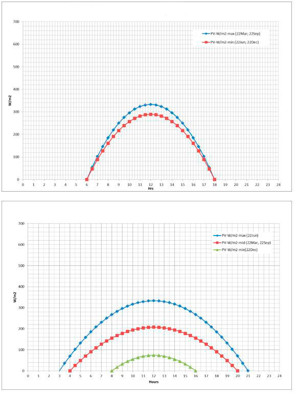
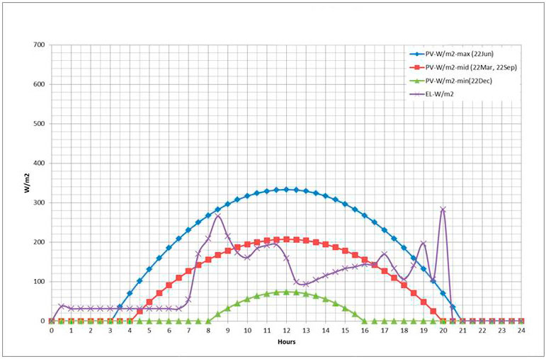
The recent progress in FC technologies has led to rapid developments in ground vehicle transportation. This paper presents the results of a study concerning the feasibility of a reversible fuel cell power supply system for a solar-panel-powered lift operating in a high-rise building. It is assumed that all energy needed to power the elevator system will originate from the solar panels. Two geographic locations are considered: the best possible solar irradiation in Kampala (Equator) and mid-Europe 52° north parallel (London). The solar irradiation [W/m2] curves have been derived from available data [2] and are shown in Figure 1.
In both cases, the lift daily energy needs are balanced with the energy stored in a buffer battery set, which has to satisfy two main requirements: store enough energy for daily operations (with reasonable margin for the cloudy weather) and the capability of charge/discharge current at peak power periods (e.g., motor start power, break energy accumulation).
2. Energy Requirements
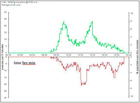
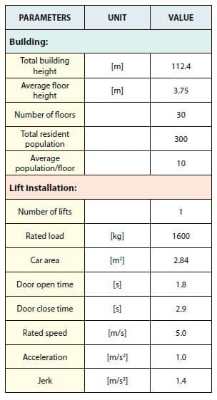
A simplified model of high-rise lift installation has been considered to generate the lift power requirements and energy consumption. The corresponding building data and the lift installation parameters are shown in Table 1. The lift energy simulation model implemented in a commercial simulation software package Elevate™[3] has been used to determine the lift power requirements and energy consumption. Siikonen’s full-day office template was used to generate the passenger demand data[4] (see Figure 2).
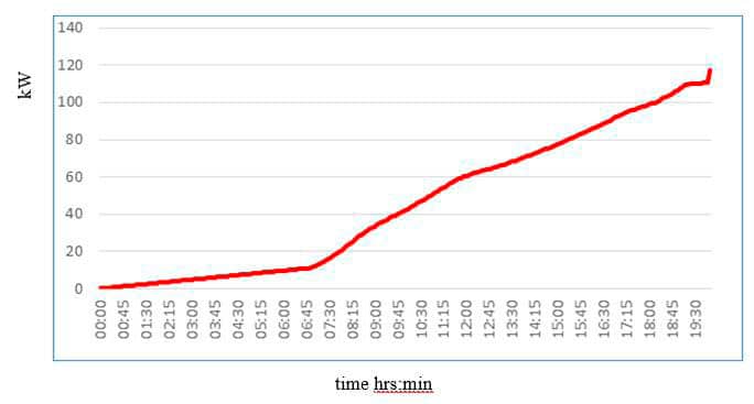
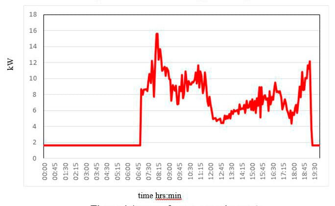
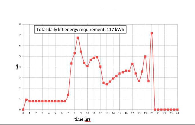
Figure 3 illustrates the simulated cumulative energy consumption data, and Figure 4 shows the averaged power requirements. The lift energy requirements over time are then derived from the cumulative energy data, and the corresponding curve is shown in Figure 5.
The available sun energy depends on the daily and seasonal irradiation fluctuations. Different energy storage strategies have been adopted to adapt the lift operation scenarios to these cases.
Table 1 Main model data
These scenarios are outlined as follows:
- The energy required is balanced with the energy stored in a daily buffer battery sized for the available sun energy on:
- 22 June at the Equator location
- b. 22 September at the 52° north location.
It is considered that the seasonal energy imbalances/ fluctuations can be covered in the following ways:
- The grid access is possible;
- The sun’s excess energy is stored in the grid at times when the excess energy occurs
- b. The lift energy deficits are covered from the grid at times when the sun energy is inadequate
- The Grid access is not possible
- The sun’s excess energy is stored in the seasonal battery bank when the excess energy occurs, while the energy deficits are covered from the battery bank when the sun energy is not adequate
- The sun’s excess energy is stored in the hydrogen gas generated (water electrolysis) when the excess energy occurs, while the energy deficits are covered from the FC operations through hydrogen conversion into electricity.
3. Power Supply Systems for Energy Storage Strategies
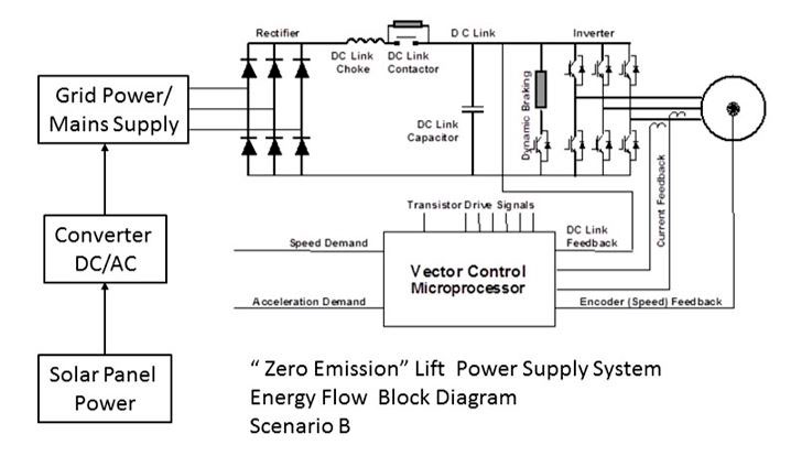
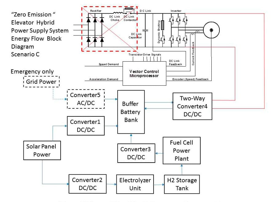
Considering the seasonal energy imbalance/fluctuations, the following lift power supply systems are considered. The diagrams in Figure 6 and Figure 7 illustrate the power supply system for scenario B and scenario C, respectively. It should be noted that the diagram in Figure 7 covers two cases: C)a and C)b, respectively.
The Case C)a can be realized when the FC/Electrolyser loop is omitted and when the buffer battery bank size is increased to cover the seasonal sun power fluctuations.
4. Buffer Battery Size – Daily Energy Fluctuations
4.1 Battery Size for Daily Lift Operations
Considering that the lift power requirements don’t correspond to the available sun energy periods (e.g. day-night), the buffering battery bank is proposed. In this scenario, the battery is sized for charging from photovoltaic (PV) solar panels to cover the daily lift energy requirement. The minimum required battery size for daily operations is estimated at 79 kWh based on the data shown in Figure 8 (assuming 100% capacity margin for a “cloudy” day). It should be noted that the lift power requirement is related to the unit area (1m2) of PV panels.
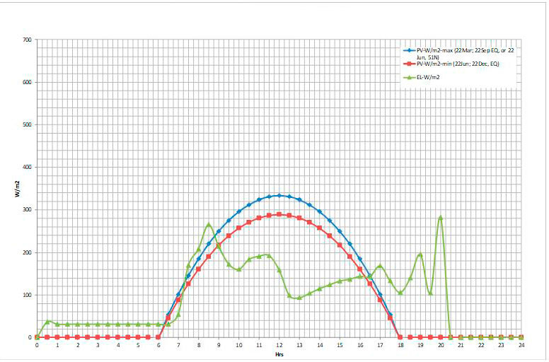
The diagram in Figure 8 presents the comparison of the sun’s available energy on the minimum energy day (area below the red line) with the lift’s daily energy requirement (area below the purple line) for locations near the Equator. Sizing PV panels for the minimum energy day is likely to result in a cheaper solution than sizing the PV panels between the blue and red lines and installing any seasonal energy fluctuation compensation device.
For locations near the 52° north parallel, the situation is dramatically different. By comparing the graphs in Figure 1, it becomes clear that the PV panel surface would need to be very large in order to cover the daily lift power requirement on the minimum sun energy day (22 Dec) -green line, bottom graph. In this case a seasonal energy fluctuations compensation device will likely be required, while the PV panels would be sized to match the annual energy requirement need.
4.2 Battery Size for Lift Maximum Power Operations
The battery size is also linked to the load power and charge current limitation. A typical 3C Li-Ion battery’s current limitation is 300 A. For the selected 100-Ah, 12-V battery and 165-kW peak lift power, the minimum buffer battery size is 55 kWh.
Comparing the battery sizes from cases 4.1 and 4.2, the 79 [kWh] battery bank size is suitable to cover both the daily Sun power fluctuations and the battery charge current requirements.
5. PV Panels Size and Battery Buffer Size
5.1 PV panels size for operations near the equator
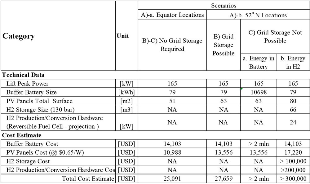
The required PV panels surface area for operations near the Equator is determined to be 51 m2, assuming the PV conversion efficiency at 37%. The comparison of major component costs is provided in Table 2. There will be no need for the seasonal energy storage – see the maximum (blue) and minimum (red) irradiation curves in Figure 8.
5.2 Buffer battery size – seasonal energy fluctuations (52 deg north)
One of the seasonal energy storage options is to use the battery bank. The required battery capacity calculations that have been carried out indicate that this option is not a plausible solution – the energy storage would require 9,906 batteries of 100 Ah each, while the PV panel surface area would be 50 m2. The cost of batteries would then be of about US$2 million.
6. H2 Storage and FC Size – Seasonal Energy Fluctuations (52° north)
Another seasonal energy storage option is the Electrolyser-H2 Storage-FC Power System. The main system components are presented in Figure 7. The operating strategy involves harvesting the sun energy during high-irradiation periods, converting it into hydrogen through water electrolysis, storing hydrogen in pressurized tanks and converting the hydrogen back to electricity in the FC at the low-irradiation periods. The electrolysis/fuel cell round-trip efficiency is around 45%, which impacts on the required PV panel size/surface area during the high-irradiation energy harvesting. In this case, the needed PV panel surface area is determined as 80 m2.
It should be noted that the lift power requirement is per the unit area (1m2) of PV panels. The required hydrogen amount for energy storage is 7,925 Nm3. The maximum H2 storage pressure is 130 barg due to the electrolysis process limitations. [5] However, at this point only prototypes of such electrolysers are available. But, bearing in mind the rapid progress in FC technology, it can be assumed that the commercial 130 barg electrolysers will be available soon and the high-pressure H2 compressors will not have to be used due to their high cost.
The required H2 tanks volume (to store water) is 66 m3, which might be not practical for installation in the high-rise building. The cost of tanks would exceed US$100,000. The cost of four Nm3/hr, 30 barg PEM electrolysers is around US$200,000. The cost of FC for H2 conversion is comparable to the PEM electrolyser cost.
The Unitized Reversible FC technology, which combines electrolyser and FC in one device, is in the prototyping stage and, once developed, it might cut the H2 conversion hardware cost by 50%.
Assuming the required advanced technology is commercially available today, the cost of H2 production infrastructure would exceed US$300,000.
7. Conclusion
A comparison of the scenarios considered in this study is presented in Table 2. Two geographic locations have been considered in the analysis: near the Equator and at 52° north, which corresponds to London’s location.
The analysis carried out shows there is no need for the seasonal energy storage in the areas close to the Equator due to the high solar power availability through the entire year. Daily energy balancing can be covered with a battery pack, which is much cheaper than the electrolyser-FC system of the comparable energy storage capacity (US$25,000 vs US$200,000); refer to cases A)a; B)-C), respectively. The need for seasonal energy storage arises at the locations away from the Equator. The simplest and most cost-effective way to deal with the seasonal energy storage in these locations is grid energy storage (see cases A)b; B, respectively).
When the grid energy storage is not available (case A)b; C)a and C)b), the cheaper solution is energy storage in hydrogen rather than in li-hydrate battery. However, the size of H2 storage tanks (66 m3) might result in safety concerns if located near a high-rise building. Considering 2-m-diameter tanks, the total length of tanks would be about 21 m.
Careful layout planning will be required if such a solution is adopted, assuming the high cost is not an issue. Seasonal energy storage in a battery pack is the most expensive of all considered scenarios. It is relatively safe, but still requires a considerable amount of real estate space to house the batteries. The expected battery mass is 214 T, while the battery storage volume would be around 200 m3, including the space for connections and cooling.
The overall conclusion is that the grid-independent lift energy supply system is possible; however, the cost and space requirements are major limitations in the seasonal energy storage in hydrogen form.
It should also be noted that there are hazards associated with the application of fuel cell technology in the built environment. The main hazards involved are related to the hazardous properties of hydrogen and its storage. [6] The hazards include fire and explosion, as well as electrical hazards. Therefore, controlling the risks involved need to be considered.

References
[1] J.P. Andrew and S. Kaczmarczyk, “Systems Engineering of Elevators.” ELEVATOR WORLD, 2011.
[2] Worldatlas.com https://www.worldatlas.com/articles/how-long-is-a-day-at-the-equator.html (Accessed 15 February 2020)
[3] L. Al-Sharif, R. Peters, R. Smith, “Elevator energy simulation model.” Elevator Technology 14. Proceedings of ELEVCON 2004, Istanbul, Turkey, April 2004, 11-20.
[4] M.L. Siikonen, “On Traffic Planning Methodology.” Elevator Technology 10. Proceedings of ELEVCON 2000, Berlin, Germany, May 2000, 267–274.
[5] V.N. Fateev et al., “High pressure PEM water electrolysis and corresponding safety issues.” International Journal of Hydrogen Energy 36(3), February 2011.
[6] Health and Safety Guidance HSG243, Fuel cells. “Understand the hazards, control the risks.” Health and Safety Executive, 2004.
Get more of Elevator World. Sign up for our free e-newsletter.


