
An LCL filter aids the conversion of elevator feedback energy to AC for it to be safely sent back to the grid.
by Wang Yanqing, Jiang Qing, Cao Jie and Wan Jianru
The energy generated in the regenerative state of elevator frequency-control systems is very impressive. This energy is transmitted to the capacitor on the DC side of the inverter and could generate a voltage surge if not dealt with. It is a serious threat to the system. If the renewable power is rationally used to avoid the DC-side capacitor voltage of the inverter pumping up, system safety is ensured. The elevator feedback energy can be converted to AC by a three-phase inverter with a three-order LCL filter (composed of inductance, capacitance and inductance) and sent back to the grid.
Compared with a conventional L-type inverter, an LCL-type inverter only requires small inductance and can take both low-frequency gain and high-frequency attenuation into account. However, it is a third-order system without damping, and its high-amplitude peak is at the resonant frequency of its turning points. The mathematical models of a three-phase, grid-connected inverter with LCL filter are described in the two-phase rotating coordinate system. The control strategy is using the power as an outer ring; the inner ring includes the inverter-side inductance current and capacitor-current feedback, which is the active damping control strategy. It can enhance system stability, filter out the higher harmonics effectively, reduce costs and reduce system size. It also can improve the power factor and reduce pollution of the grid caused by variable-frequency drives. On the MATLAB/Simulink platform, 7.5- and 10-kW systems are simulated to verify the reliability of this method.
Grid-Connected System
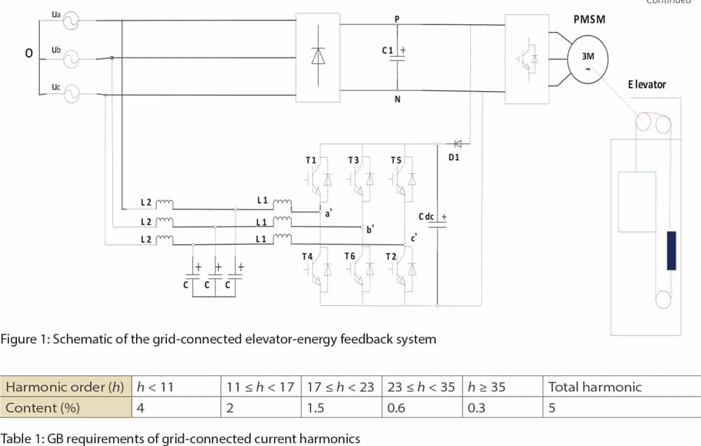
The grid-connected elevator-energy feedback system schematic is shown in Figure 1. It consists of a three-phase, full-control bridge inverter, LCL filter, DC bus capacitor and diodes. When the elevator is traveling upward with a light load, downlinks with heavy load or decelerates with its brakes, renewable energy is rectified to DC through the inverter freewheeling diodes. The DC bus capacitor voltage increases. The converted current meets the Chinese standard (GB) requirements of grid harmonics (Table 1).
Mathematical Models
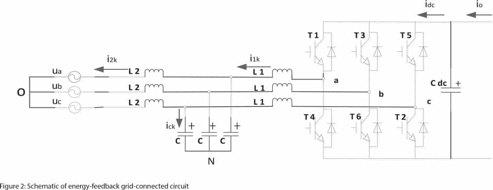
The energy-feedback grid-connected circuit with LCL filter is shown in Figure 2. The grid three-phase voltage is defined as:
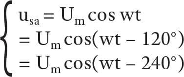
Um is the phase voltage amplitude, and the parasitic resistances of capacitance and inductance are ignored. According to Kirchhoff’s laws, the mathematical models (Equation 2) of the three-phase grid-connected inverter are established in a three-phase stationary coordinate system.
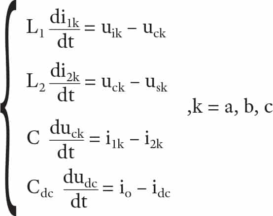
Sk is a switching function for the bridge arm. “1” represents the tube above is open and the tube below is off, while “0” represents the tube above is off and the tube below is open. i1k is the inverter-side inductor current; i2k is the grid-side inductor current; uik is the inverter output voltage; uck is the LCL filter capacitor voltage; udc is DC bus voltage; idc is the output current of the DC bus; O is the grid midpoint; and N is the AC capacitor midpoint. For a symmetrical three-phase, three-wire system, the inverter output voltage can be described as ![]() .
.
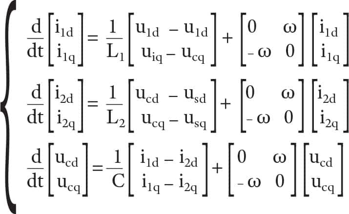
Although the physical meaning of the mathematical model in a three-phase stationary coordinate system is clear, it is difficult to achieve no static error adjustment. To facilitate the analysis, variables in the a/b/c-axis coordinates are converted through equal power conversion to the same grid fundamental as the synchronous-frequency rotating direct- and quadrature- (d/q) axis coordinate system, such as Equation 3:
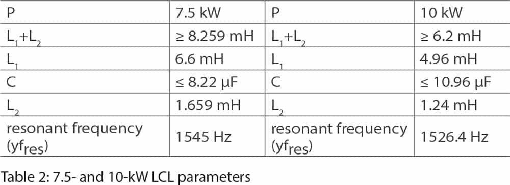
The method of LCL parameters’ design is according to Shi Liguang’s “Research on Proportional-Resonant Controller for Grid-Connected Converter with LCL-Filter,”[1] and to ensure optimal parameters, they were verified on the resonant frequency. DC-side active power values of the inverter are, respectively, P = 7.5 kW and P = 10 kW. The parameters are designed in accordance with L1/L2 = 4 (Table 2). Known conditions are grid voltage root mean square: Un = 220 V; DC-bus voltage: Udc = 650 V; and switching frequency: fsw = 5 kHz.
Control
The Analysis of Control Strategy
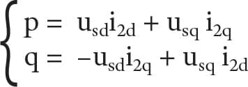
The Instantaneous Power Theory was proposed by H. Akagi and A. Kanazawa in 1983.[2] It is built on the basis of coordinate transformation. Instantaneous active and reactive power are calculated according to the instantaneous value of the two-phase coordinate transformation. To overcome the traditional theory of active and reactive power, the calculation is based on the average of the definition of the cycle. The computational delays caused by the accumulation period, which will help control strategy to make decisions using the instantaneous power, are reduced. To facilitate the PQ decoupling control, the direction of the resultant vector of the grid voltage needs to be chosen as the d-axis direction.
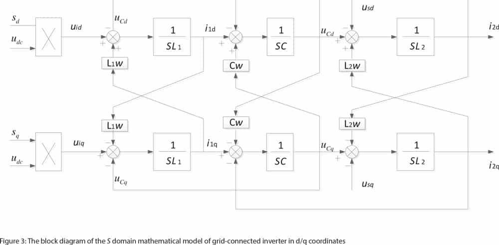
Based on Equation 3, the grid-connected inverter’s mathematical model of continuous domain block diagram can be obtained in the two-phase stationary coordinate system (Figure 3). The coordinate transformation introduces strong couplings between the d/q-axis components of the system. Without decoupling, the controller design will become complicated, showing that the current control effect is not very satisfactory.
The d/q-axis decoupling control of LCL grid-connected inverter in the two-phase rotating coordinate system is shown in Figure 4.
Controller Design
The LCL filter has a good filtering effect on higher harmonics, but its high-order features make grid current have undamped resonance, which puts forward higher requirements on the closed-loop design. Its resonant peak must be suppressed to overcome the undamped characteristics. The active-damping strategy is to take the filter capacitor current and voltage feedback to suppress the resonant frequency harmonic.[3 & 4]
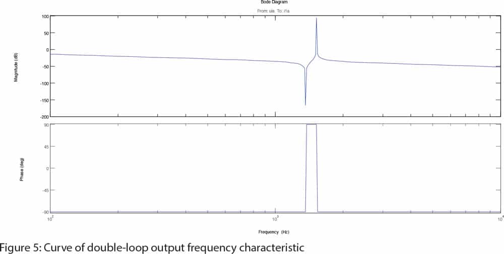
The frequency characteristics from the inverter-side voltage to the inverter-side inductor current for the 7.5-kW system is shown in Figure 5. There are two resonant peaks, the second of which is caused by a series resonance of L1, L2 and C.[5] The same problem exists in 10-kW systems.
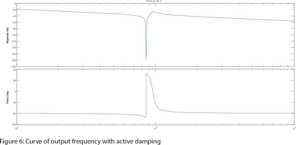
With active damping, in the series resonant frequency, the controller can better inhibit the shock (Figure 6).Considering the decoupled d/q-axis current inner symmetry, this article only covers the design of id current loop proportional-integral-controller (PI) parameters.
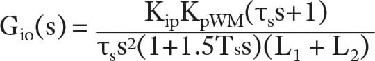
The open-loop transfer function of Figure 7 is:
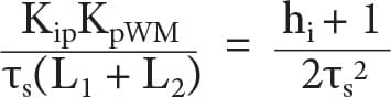
The existence of a large overshoot in the current-regulation process is not allowed. This is to achieve rapid current-tracking performance for the dynamic requirements of the current loop. The current loop’s PI parameters are designed according to the typical type II system, and the appropriate intermediate-frequency bandwidth is defined as hi = τs/([1.5T]s). hi = 5 is often taken in engineering. Parameter relation is according to the typical type-II system, in which we have:
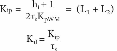
Thus, the solution is:
Simulation Results Analysis
The system model is built in MATLAB/Simulink according to the design parameters in Table 2 and aforementioned controller-design method (Figure 8).
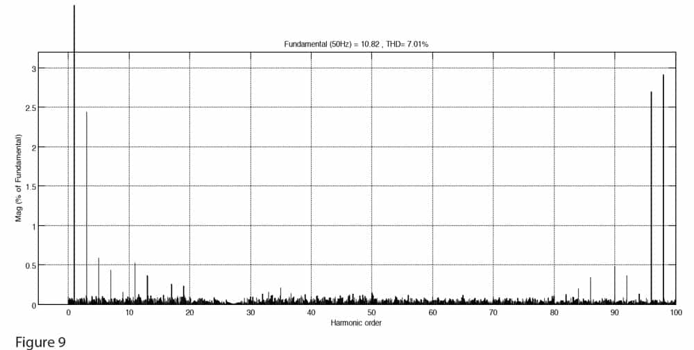
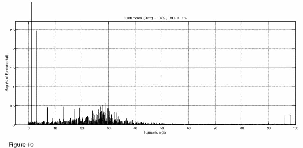
Figures 9 and 10 are the currents of, respectively, the 7.5-kW inverter and grid side’s total-harmonic-distortion (THD) analysis. Filtered by LCL, the switching frequency harmonics fall below 0.5%, and total harmonics fall to 3.11% (from 7.01%). The harmonics meet the requirements of Table 1. Grid current distortion rate is low. Figure 11 shows that the power factor is close to 1; unity power tracking, which meets the grid-connected condition, is thus realized.
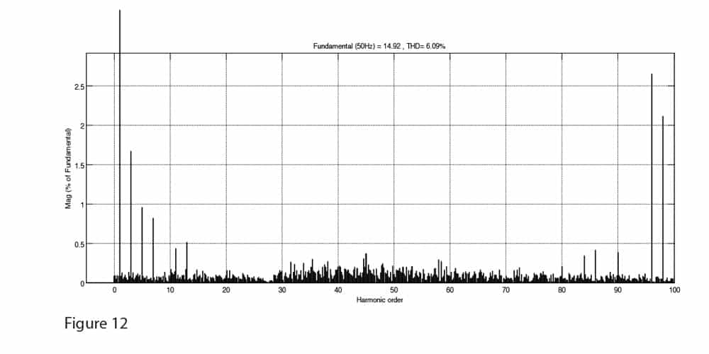
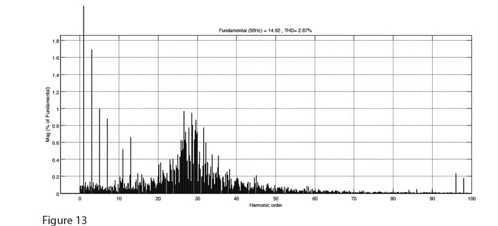
Figures 12 and 13 are, respectively, the 10-kW inverter and grid side’s THD analysis. Filtered by LCL, the high harmonics are obviously suppressed; total harmonics fall to 2.68%, which meets the requirements of the grid current harmonics.
Conclusions
Through simulation experiments on 7.5- and 10-kW systems, the results show that LCL filter can effectively suppress the harmonics. The inhibiting effect on the switching frequency is more obvious, and the current harmonics are significantly reduced. Using power outer loop control, the power factor is close to 1. The filter capacitor current and voltage-feedback control significantly enhance the stability of the system. The simulation results proved the feasibility of this method in elevator applications.
References
[1] Shi Liguang. “Research on Proportional-Resonant Controller for Grid-Connected Converter with LCL-Filter,” Tianjin University, 2013.
[2] Akagi, H.,Y. and Kanazawa, A. Nabae. “Generalized Theory of the Instantaneous Reactive Power in Three-Phase Circuits,” IPEC 1983, 1375-1386.
[3] Xu Jinming, Xie Shaojun and Xiao Huafeng. “Research on Active Damping Control Mechanisms of LCL Filter,” Proceedings of the CSEE, 2012.09: 27-33 +6.
[4] Zhang Xing and Zhang Chongwei, “PWM Rectifier and Control,” Beijing: Mechanical Industry Press, 2012.02.
[5] Qiu Zhiling, “The Study on Key Techniques of Three-Phase Three-Line Grid-Connected Converter Based on LCL-Filter,” Zhejiang University, 2009.


Get more of Elevator World. Sign up for our free e-newsletter.


