Early 20th century publisher sought to explain practical applications of electricity in a 10-volume series.
In 1917, Theodore Audel & Co. of New York, publisher of technical manuals and educational materials, published a 10-volume series titled Hawkins Electrical Guide. The series’ namesake was Nehemiah Hawkins (1834-1928), a well- known author, editor and owner of Theodore Audel & Co. The series was described as “A progressive course of study for engineers, electricians, students and those desiring to acquire a working knowledge of electricity and its applications.”[1] The title page for each book included two simple statements that announced the educational and editorial approach: “The thought is in the question. The information is in the answer.”[1] This approach was explained in the preface to the series, which was included in volume one:
“The Guides are written partly in the question-and-answer form, as this style of presentation has met with hearty approval, not only from those of limited education, but also from the better informed. The special aim of the author has been to give short and direct answers, in such plain language as to preclude a misconception of the meaning. With this in view, the answer gives simply the information, sought by the question. The answer is limited to one paragraph so that the reader may concentrate upon the fact or facts demanded by the question. Any enlargement of the answer or specific explanations of items contained therein, are presented in separate paragraphs. With this plan of separating the answer, as it were, from items of secondary importance, and making it short and simple, its content is more forcibly impressed upon the mind of the reader.”[1]
The author also chose to place detailed information, which would help the reader understand the answers to the questions, in an unusual place:
“In a text book, it is necessary to illustrate and explain the various species of commercial apparatus met with in practice, and in this connection, the publishers desire to call attention to the manner in which the author has treated what may be classed as the ‘descriptive matter.’ Contrary to the usual custom of giving descriptions of commercial machines in the main text, where they would occupy considerable space, to the exclusion of the more important matter, all such descriptions are placed in small type directly under the illustrations, leaving space for an adequate presentation of the underlying principles, theories and for the large amount of practical information that is essential to obtain a general knowledge of electricity.”[1]
Thus, Hawkins’ strategy focused on critical “underlying principles and theories,” as well as the “practical information” needed to obtain a “general knowledge.”[1] The first chapter in the final volume of this series, Hawkins Electrical Guide (Number Ten), employed this unique approach to explore and explain electric elevators.
The 70-page chapter on electric elevators addressed 91 individual topics, which were examined by 34 questions and explained (in part) by 36 drawings, 29 photographs, 21 wiring diagrams and one chart. Hawkins’ approach to education may be illustrated by examining a typical question, its answer, the supporting text, and a related illustration and its caption. The material on traction elevators, the newest system on the market at the time, included, “What difficulty is sometimes experienced with traction elevators? Answer: Slippage.”[2] The one-word answer was immediately followed by an explanatory paragraph:
“With all traction elevators, there is the danger of slippage of the cables on the driving drum, especially if the cables become greasy. This slippage is most noticeable when the operator endeavors to stop in descending with a heavy load, with the result that on high-speed cars when attempting to make a quick stop, the car sometimes slides past the landing, even to the extent of one or more stories. The fact that the traction drive is not a positive drive is a safeguard for the reason that cable strains can never increase beyond a certain limit, well within the factor of safety of the cables and fastenings. This means that the danger of the car or weight dropping, as a result of being pulled into the overhead work, and thus breaking cables or fastenings, is eliminated.”
The illustrations that accompanied this section included a drawing of an “Otis over-mounted 1-to-1 traction elevator” (Figure 1). The information found in the drawing’s caption followed Hawkins’ strategy of placing manufacturer- specific material outside the main body of text:
“The machine consists essentially of a motor, a traction driving pulley, and a magnetically released spring applied to brake, compactly grouped and mounted on a continuous heavy iron bed. The motor is of the slow-speed shunt-wound type. The drive from the armature spider to the pulley is affected through a flange integral with the spider and bolted directly to the pulley, thus eliminating torsional strains on the shaft and the use of keys. The control is full magnet; that is, the controller is actuated by a master switch in the car. The object of the oil buffer is to act as a cushion in bringing either the car or counterweight to a positive stop through the displacement of the oil.”[2]
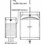
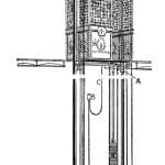
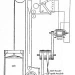
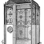
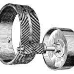
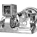
In addition to the examination of electric elevator types (belt-driven and drum machines were also discussed), the chapter included material on cars and shafts, motors, elevator controllers, drive systems (gearing types), and operational characteristics. Each of these topics was supported by a diverse set of illustrations (Figures 2–6).
The sources for the chapter’s images and contents included materials obtained from 16 different companies:
- A.B. See Elevator Co.
- Albro-Clem Elevator Co.
- Burdett and Roundtree Manufacturing Co.
- Cutler-Hammer Manufacturing Co.
- D.H. Darrin Co.
- Elektron Manufacturing Co.
- Fraser Electric Elevator Co.
- Gurney Elevator Co.
- Kaestner and Hecht Co.
- National Elevator Co.
- Northern Engineering Works (spur-geared machine)
- Otis
- Portland Elevator Co.
- Reedy Elevator Co.
- Sprague Electric Elevator Co.
- Warner Elevator Manufacturing Co.
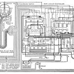
These businesses represented a diverse group of regional and national companies from across the U.S. It was not uncommon for companies to share technical descriptions, photographs and drawings with publishers. This shared content typically derived directly from manufacturers’ catalogs and was viewed as promotional material. However, the inclusion of 21 elevator controller wiring diagrams was unusual. This type of technical material was not featured in most catalogs, and many companies carefully restricted access to this often-proprietary information. Thus, the fact that nine companies (including Otis, which rarely shared this type of information) furnished these drawings is intriguing and, perhaps, speaks to the author’s power of persuasion. It is interesting to note that none of the wiring diagrams featured a lengthy, detail-filled caption similar to those that accompanied all of the other illustrations.
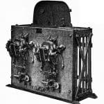
Readers were only given a brief statement that identified the company and controller type (Figure 7). By comparison, Cutler-Hammer, which furnished numerous photographs of controllers (but no wiring diagrams), provided detailed captions for all their equipment featured in the text. Figure 8 and its accompanying caption (see below) are representative examples. The caption continues:
“25 to 60 cycle circuits with two- or three-phase slip-ring induction motors, where rated full-load rotor circuit does not exceed 150 A per phase. It consists of a three-pole, drum-type reverse switch and a secondary self-starter, the two being assembled on the same frame and interconnected. The drum switch, which performs the functions of both line and reverse switch, controls the starting, stopping and reversing of the motor, and is designed to be suitably geared to the operating shaft of the elevator. As the reverse switch affords the only control over the line circuit, it is essential that the operating cable from the car be provided with a centering device. The acceleration of the motor is automatic and is accomplished by the secondary self-starter, which is of the series relay type. Automatic stopping at the travel limits must be affected by the traveling nut device on the elevator machine.”[2]
It was assumed that the underlying principles and theories found in the text would provide the information needed to understand the material found in the captions.
The chapter concluded by offering readers practical advice on elevator operation. This discussion opened with a gentle reminder that “anyone who has tried to stop an elevator at a floor will agree that it cannot be done without experience.”[2] Automatic leveling devices were not developed until the 1920s; thus, precise landing stops required experienced and skilled operators. The advice on
operating procedures covered the entire workday. Elevator operators typically arrived prior to the start of business. Their first task was to confirm that the switch controlling the elevator’s power supply was turned on. Their second task was to test their assigned elevator to ensure that it was working properly:
“Operators are usually instructed to go to the switchboard every morning before entering the car and to test the operation of the elevator by means of a try out switch, so as to ascertain that every part of the installation is operating properly. In this way, the car can be run up and down the shaft several times each morning, testing not only the control apparatus, but also the motor, limit switches, brake solenoids, etc.”[2]
The design of the “try out switch” was such that it was “not possible to operate the elevator from the car” while it was in use.[2] However, while this task was clearly defined, it is unclear how the operator, standing at the switchboard, could verify that the elevator was operating properly.
The advice on car operation reflected other normative daily activities. Operators were advised to start their car “gradually, although in order that a reasonable average speed be maintained between floors, the acceleration must be rapid.”[2] Stops should be made level the first time to avoid inching up or down: “If the stops can be made within the distance that the operator can see the landing, the best results will be obtained for moderate-speed cars. This allows the operator about 8 ft in which to bring the car to a stop from full speed.”[2] Operators were also advised not to rely on the limit stops at top and bottom landings, but to approach these in the same manner as all floor stops. However, best practice suggested that they “test the adjustment of the limit stops and determine if they remain in proper working order by trying them once daily by means of the car.”[2] Operators were also reminded that no passengers should enter or exit their car until it had come to a complete stop. They were advised, as they “opened the doors at a landing, to call out ‘Up’ or ‘Down,’ depending upon the direction in which the car is making the trip, and, while they should allow ample time for passengers to reach the car from wherever they may be standing, it may be necessary in certain cases to add, ‘Step lively, please.’[2] At the end of the workday, all cars were to parked at the lowest landing and the power switched off “to prevent any possibility of the motor starting up and causing damage,” and to prevent unauthorized use.[2]
This brief overview of the presentation of electric elevators contained in Hawkins Electrical Guide (Number 10) parallels previous ELEVATOR WORLD history articles that examined other educational materials produced in the early 20th century. Future articles will continue this investigation with regard to a comparative study of the major textbooks with regard to similarities and differences in content, focus and editorial strategy.
- Figure 1: Otis over-mounted 1-to-1 traction elevator[2]
- Figure 2: Electric drum machine elevator[2]
- Figure 3: Belt driven elevator[2]
- Figure 4: Modern elevator car[2]
- Figure 5: Gurney Elevator Co., herringbone gear, pinion and brake pulley[2]
- Figure 6: Warner Internal spur gear freight elevator machine, fitted for mechanical control[2]
- Figure 7: Diagram of Otis type MF4 direct current magnet controller for traction elevator[2]
- Figure 8: “Cutler-Hammer alternating current, reversible, single-speed, semi-mechanical controller with self-contained reverse switch for slow speed passenger or freight elevators.”[2]
References
[1] Hawkins, Nehemiah. Hawkins Electrical Guide (Number One), New York: Theodore Audel & Co. (1917).
[2] Hawkins, Nehemiah. Hawkins Electrical Guide (Number Ten), New York: Theodore Audel & Co. (1917).
Get more of Elevator World. Sign up for our free e-newsletter.
