How Elevator Door Interlocks and Brake Circuits Influence Each Other and Cross-Cycle Protection
Jul 1, 2011
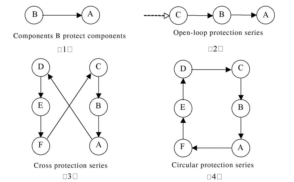
This paper provides a control mode of cross protection, which is different from secondary protection.
This paper will provide a control mode of cross protection, which is different from second protection. The second protection is redundant and it can increase the cost of the system. Secondary protection, which is behind a protection, is a weak link, namely because the secondary protection itself is no longer protected. Cross protection does not increase new protection; it only increases mutual association between the existing protection. In cross protection, each of the protection components that exert protection are protected, as well. The key problem of cross protection is solving deadlock, which is possible in the control process. Door-Interlock and
Brake-Circuit Protection
The door and brake are two important safety components in elevators, but they have faults that may lead to shear and pulley accidents, falls, etc. The most dangerous of these is a shear accident, which occurs when the car moves with the door open. This is a dangerous situation, because it is directly related to the faults of the protection circuit of door interlocks and brakes.
The door interlock consists of all car and landing door electrical switches and is connected as the doors close. It is also a necessary safety signal for elevators to begin operating. If the door interlock lines are partially welded or short-circuited, the door circuit, which has also been short-circuited, will be connected even if the door is open. There-fore, the door interlock circuit must add anti-weld (or anti-short-circuit) protection in order to avoid this dangerous situation.
The brake-control circuit is at a different angle to prevent the elevator from moving with an open door. When the elevator is parked in the station, passengers can go in or out of the car, and the car door and landing door will open; at this time, the elevator can’t move, or a shear accident could occur. But, if the brake electrical circuit is short-circuited, the elevator can’t stop by brake and will move with the door open. There-fore, the elevator brake circuit must have protection to prevent a short-circuit.
In order to prevent a brake short circuit there are two protection methods: 1) The interruption of the brake current shall be effected by at least two independent electrical devices. If one of the contractors has not routinely opened the main contacts, then the other contractor should routinely open the main contacts; 2) Setting contacts to monitor the circuit. If the elevator is stationary, one of the contractors has not opened the main contacts. Further movement of the car shall be prevented at the next change in the direction of motion.
But, to ensure two independent contacts is very difficult, because this is involved at any control level. Although two controllers of the brake are in different circuit and control modes, they are controlled in a higher level by a control contact, which can have a welded or short-circuit. These two independent contacts can still suffer failure by loss of independence. Since the independence of two contacts is difficult to guarantee, the best way to guarantee reliability of the monitoring circuit, (as long as the brake circuit contact has a welded or short-circuit) is to monitor the circuit and immediately stop operation lines, including coil circuit of the brake, so that even though the two contacts have a welded or short-circuit at the same time, the main motor and brake can also be stopped.
Protection-Series Settings
How can the reliability of the monitoring circuit be guaranteed? This problem starts by determining whether the anti-short-circuited relay or electrical device itself has a welded or short-circuit. But, this problem is not simple. For example, part “B” protects part “A;” the safety of part “A” gets a temporary solution, but if part “B” hap-pens to fail, the protection of “A” may also fail. Although “A” and “B” are two different parts, failure of both at the same time appears to be less likely; but, if part “B” fails first, and the system which has not found the fault continues working, the failure of part “A” becomes much greater. In order to avoid this type of circumstance, a third part, part “C” is needed to monitor part “B.” But, the system costs will increase, and the question of failure will not have been solved thoroughly. Because part “C” still has the possibility of having a problem, another part is needed to monitor part “C.” Carrying on like this is actually an infinite series which is difficult to realize (it is like the open-loop protection series shown in Figure 1). In addition, there are many parts that need protection in elevators, so the situation is, in fact more complex.
Cross Protection and Deadlock Prevention
In order to solve the problem in Figure 1, a protective series known as “cross circulation protection mode” can be adopted. In this mode, each component protected is also a protection to the other component. The entire protection series itself consists of a closed-ring structure, so that one can use limited protection series to solve the problem of infinite protection series. Section 3 of Figure 1 is a cross-protection series, and section 4 is a circular protection series. These two modes of topological structure are actually the same. Although cross-circulation protection structures have many forms, their basic structure is a ring. At the electric parts protection system, not all of the parts need such a protection method, but for important parts, this mode should be used.
The cross-protection series, which is essentially a circular protection series, involves mutual control of parts, so it is possible to have deadlock. Deadlock is a typical problem that the circular control structure must solve. Not only can it appear in hardware, but also in software. In fact, the concept of deadlock is proposed just in the computer-control software at first. Deadlock is usually caused by circular waiting for working conditions or resources. Because of circular waiting and mutual need, a few processes or components do not go forward, causing indefinite waiting and dead halts.
In general, computer software control is varied, and random events can occur; therefore, the practical control process cannot be accurately estimated beforehand, so it is difficult to avoid deadlock. But, in elevators, the control process is comparatively fixed and can be accurately estimated beforehand, so the deadlock can use accurate time control or adopt other measures to prevent dead halt.
Specific Crossover Protection Control
The elevator control system has three causes for the external circuit to not disconnect routinely: electrical contacts have been welded together, electrical circuits have short-circuited and electrical control error. It needs to be noted that these faults can occur not only in the external circuit of control systems, but also in the internal circuit boards.
For example, some signals, which output from a programmable controller or a computer board, may control external relay circuits directly. The control current is heavy; therefore, current transition may be conducted through internal small relay, and welded or short-circuit may also occur. In addition, the software control may also make a mistake, because the data may fail while being processed and transmitted. This possibility may be slim, but it does exist. Therefore, at least two sets of different detective circuits that could detect each other have to be applied for reliable protection, which is a detective mode of cross circulation that could fundamentally solve the problem in limited links.
Figure 2 shows an important control mode in the door-interlock and brake circuits. It can solve not only unlimited problems of protection through cross-circulation control, but also avoid deadlock through time control. As a result of current elevator control systems controlled by a programmable controller (PC) or computer, the circuit in Figure 2 is designed to be controlled by PC software, which is not only convenient for reading, but also easily transformed into the control mode by computer software. That’s why some relays and electrical contacts in Figure 2 are virtual ones designed by software, like MF (the relay of door interlock anti-short-circuited) and BF (the relay of brake circuit anti-short-circuited), and some remain hardware relays and electrical contacts.
Solving the Problem
In Figure 2, the front part is a circuit of a door interlock. To prevent a car from running while the door is open, all landing and car-door contacts should form a serial circuit that input the internal control system. But, to prevent contacts from a welded or short-circuit, the active landing door, passive landing door and car door should form three independent circuits that input the internal control system to test whether the contacts disconnected independently in every door opening. T1 is a serial circuit formed by all electrical contacts of active landing doors, T2 is a serial
circuit formed by all electrical contacts of passive landing doors, and J is a circuit of car-door contact. The disconnection function of all three contacts could be detected through the MF (door interlock, anti-short-circuit) circuit while the elevator is parked normally. The connection function of these three contacts can be detected through the MS (door interlock) circuit while the elevator is running, and at this time, MF keeps its form by self-holding contacts. In the inspection or maintenance condition, the MF detection function can be temporarily shielded, so as to facilitate the inspection operation.
VF is a frequency converter that controls a main motor. The VF is not only controlled by the door-interlock relay MS, brake circuit relay “B”, normal-operation relay “K,” upward-direction relay “SX” or downward-direction relay “XX”,” but also by the anti-short-circuited relay MF and BF. So, even if the door interlock and brake circuits are both through, the VF cannot connect as long as some contacts are unable to be disconnected as designed. Apart from disconnection, detecting each contact, respectively, MF and BF can also carry out cross detection, forming a control of closed-loop detection.
When the elevator is parked and the door is open, the MF should be disconnected and begin to detect each contact of the door interlock. But, MF cannot be connected if T1, T2 and J are all disconnected, because BF is still connected after the door is opened. The MF can be connected until the door begins to close and BF is disconnected, then MF has detected all contacts, including those of BF. When the door is closing, BF will disconnect and execute dis-connection detection on brake-control contacts; mean-while BF shall also carry out disconnection detection on MF through its delay break contact MF3 (delay normally closed contact, or delayed disconnect when relay attraction). When MF connects, MF3 will usually keep being delayed for the same amount of time it takes the door to close, plus 2 seconds (for example, the MF3 delay time is 7 seconds, if the time of closing the door is 5 seconds). That is to keep MF in a disconnected state before door closing; otherwise, BF cannot connect after MF has connected, and the cross detection of MF and BF would fail. If anyone comes in or out while the door is closing, the relay of opening the door will connect, and disconnect MF, the time of the door closing will be recorded again. If MF and contacts of the brake circuit can be disconnected as designed, the BF shall be connected after the door closes, or the elevator will be stopped by BF. So far, the disconnected detection of all contacts of the door inter-lock circuit and brake circuit, and the cross detection of two circuits have been completed.
During the inspection, the parallel contact of inspection below MF1 is connected and can shield the detection of MF, which has influence on inspection operation. At the same time, as the series contact of inspection below MF is disconnected, the self-holding circuit of MF will also be disconnected if the door interlock has been short- circuited. If the door interlock has not been short-circuited, it must be inspected once again by MF after the inspect switch returns to normal operation. This is an important way of safety protection for inspectors. In 2009, in Chongqing, China, a landing-door-lock circuit was short-circuited in inspection, and the inspector was sheared to death when he went through the landing door. The cause was the lack of the discussed protection method.
The Logic of Structure of Cross Protection
Figure 3 is a simple logic control diagram of the dis-cussed circuit. The left is the control of door interlock anti-short-circuit, and the right is the control of a brake circuit anti-short-circuit. The two controls of an anti-short-circuit must all pass, or the elevator can’t start its operation. So, on the top of Figure 3, the connection of an anti-short-circuit relay of door interlock and brake is a prerequisite for elevator operation. However, the detection of the disconnect function on anti-adhesive relays of door interlock and brake (i.e. detection on a protective device itself) is carried out in a way of mutual cross feed-back transferred to the lower part of another protective device. As a result of the discussed time controlling, the time relay MF and relay disconnection contact MF3 are applied, which not only keeps the order of disconnection and connection of BF and MF, but also avoids deadlock from resource competition.
Conclusion
If any protected parts fail in the circuit of Figure 2, they can all be protected and enable the elevator to stop operating. This forms closed-loop control within limited steps, which fundamentally solves the safety problem of the brake and door-interlock circuits. And, only on this basis, the protection function of the door-interlock and brake circuits can be fully guaranteed.
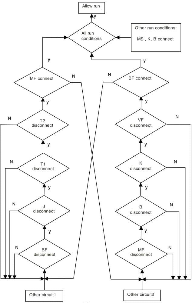
Figure 2: Door-interlock and brake circuit cross-cycle con-trol. T1: landing active door interlock relay; T2: landing passive door interlock relay; T11, T12 and T13: landing active door contacts; T21, T22 and T23 1-3: landing pas-sive door interlock contacts; J: car door interlock relay; J1: door interlock contacts; MS: door interlock relay; SX: up-ward direction contact; XX: downward direction contact; K: normal operation relay; B: brake relay; VF: frequency con-verter; BF: relay of brake circuit prevents short-circuit; MF: relay of door interlock circuit prevents short circuit; KM: open-door relay; GM: close-door relay; JX: inspecting; BZ: coil of brake; DJX: inspecting of car top; XJX: inspecting of car; JJX: inspecting of machine room 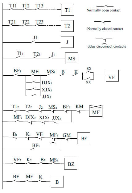
Figure 3: Locks, interlock and brake circuit cross-detect logic control chart
Get more of Elevator World. Sign up for our free e-newsletter.


