How Suspension Means Affect Cost-Effective Design And Space Efficiency
Jul 1, 2019
This component is one of the main drivers for the innovation of a complete elevator package.
Before the advent of modern elevators, hoist ropes were made of natural fibers and used to lift materials, especially into mining areas. Such environments were very harsh and aggressive against the fibers, causing them to rot quickly, giving rise to sudden breaks without notice. For that reason, one of the key factors for suspension means has always been reliability. The first metallic wire rope was invented around 1834 by Wilhelm Albert, a German mining engineer. These were used to mine in the Harz Mountains in Clausthal, Germany. At the time, Albert was looking for a more reliable means by which to periodically inspect ropes and a type that would last longer than the conventional fiber ropes and iron mine hoist chains of that era, which had proven to be unreliable.
The first twisted steel metallic rope was made of three strands with four wires each, without a core. With this specific construction, all the wires were visible from the exterior (Figure 1). This would change the users’ perception of hoist ropes.
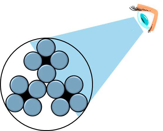
Since then, wire ropes gained quick acceptance due to their durability and superiority over fiber ropes and iron chains. They were not breaking suddenly, as signs of wear would be present if inspections were carried out routinely. This made it possible to schedule the replacement of the hoist rope before total failure.
After more than 180 years, the situation is still unchanged: steel-based suspension means, in the form of wire ropes, are still the main element of suspension for elevators around the globe, and the concept of “forecasting” the replacement of suspension means is still valid today.
Another element in elevator design is the efficient use of the space inside the elevator shaft, with the request to have smaller machines that will provide for a larger cabin in the same shaft dimensions. As the traction sheaves get smaller, the motor becomes less expensive and lighter. The motor cost and, consequently, the weight, are directly proportional to the torque generated. This latter requirement has been hard to fight until “alternative” types of suspension media that make it possible to reduce the size of the machines became available.
Reducing the bending ratio and covering the suspension means with a coating of polyurethane (PU) brought with it another problem: the definition of reliable discard criteria that was both objective and recognizable.
The aim of this article is to give an overview on the above subjects without entering a deep analysis but by pointing out the main concepts by which to understand the application and the effect on the total cost of ownership for end users.
Types of Suspension Means
Before starting any consideration on different elevator configurations, it is worth clarifying which suspension means are available on the market. Beyond conventional wire ropes, there are: small-diameter ropes, PU- coated ropes and coated steel belts (CSBs) (Figure 2).
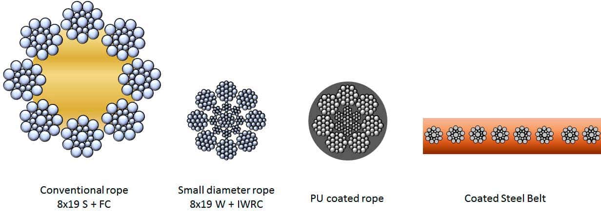
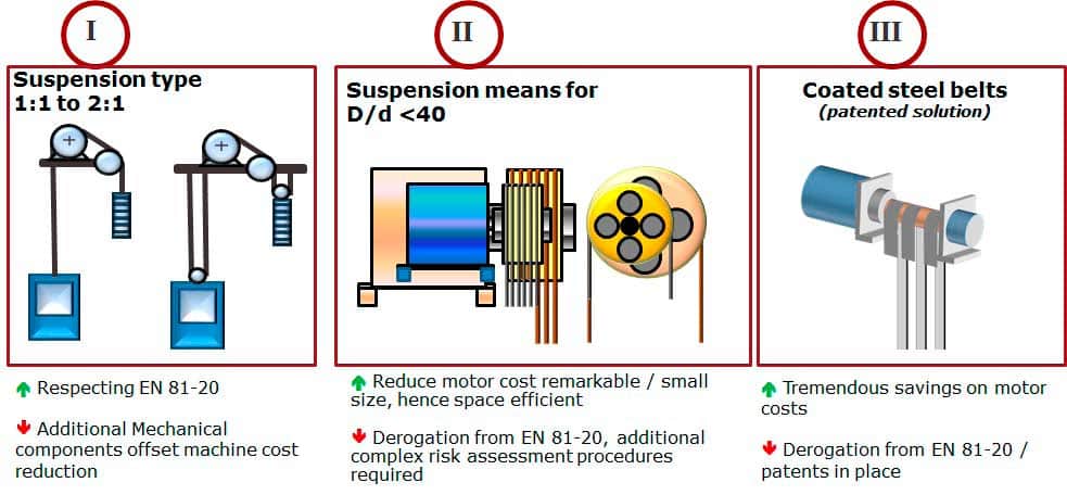
Each type of suspension means has its own pros and cons that are evaluated here in general terms. There are no strict rules in the selection of one suspension media over the others, but considerations must be drawn based on the application of the elevator, environmental conditions and traffic analysis — all known elements for elevator designers. Next, attention should be given to motor size and hoistway space efficiency. There are a few options to deal with space constrictions while saving on the motor cost (Figure 3):
The simplest way to reduce the torque of the motor is to switch from 1:1 to 2:1 suspension. This will save on the motor size, but at the same time create some drawbacks on the mechanical complexity for the complete elevator (arrangement I in Figure 3). The second possibility is to consider suspension media that allow a reduced bending ratio, D:d < 40 (small-diameter wire ropes or PU-coated ropes). In this case, the motor size could be sensibly reduced, and the space efficiency is rather consistent. However, small-diameter ropes are not currently included within EN 81-20 and would require manufacturers of small-diameter ropes to perform a risk assessment and seek a declaration certificate from a recognized certifying body. On the plus side, small-diameter ropes are under consideration to be included in a future update to EN 81-20 (arrangement II in Figure 3). A third option would be to evaluate CSBs. In this scenario, the smallest traction sheave could be used, bringing tremendous savings both to the motor cost and the increase in space efficiency. The drawback in this case is that this solution is patented (arrangement III in Figure 3).
It is also worth evaluating how much the cabin size could change within the same shaft dimensions when opting for one of the alternative suspension means (arrangements II and III in Figure 3). In Figure 4, considering that all the mechanical parts are allocated to the back side of the cabin, the gain in cabin space is readily visible, with a reduction of 30-40% of the original dimension L.
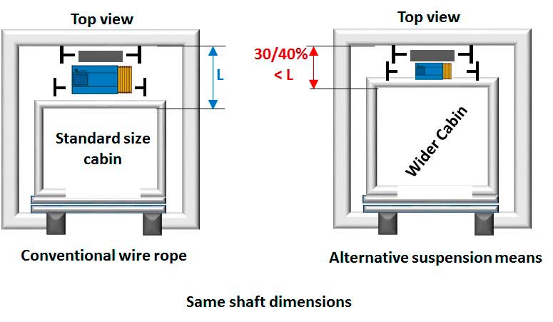
The assumption reported above could bring, in certain cases, the possibility of installing an eight-person elevator where it was previously only possible to install a six-person elevator. Furthermore, where there is a block of elevators in residential buildings, this could make it possible to install one fewer elevator, yet provide the same traffic-handling capacity. The traffic pattern must still be evaluated in a way to not increase the waiting time in front of the landing door on the ground floor too much. Alternatively, with the same number of elevators, and with the increased cabin capacity, the traffic-handling capability could be increased sensibly.
All the considerations mentioned here are valid in the case of low- and mid-rise buildings. When it comes to high-rise projects or heavy-duty applications, other elements must be considered and are outside the scope of this article. Depending on the need of the specific low- or mid-rise project, one consideration or the other could bring savings that were not available without the alternative suspension means.
Definition of Discard Criteria
Development of and enhancements to suspension means for elevators have always been related to the original concept of a visual inspection. When the first applications for small-diameter ropes and belts arrived on the market, the key concern was how to easily and reliably detect the discard criteria.
Regarding conventional wire ropes, the discard criteria is to be based on visual inspections: checking for diameter reduction, counting the number of wire breaks, identifying the points with deformations, noticing the appearance of rouging, etc. This reference rule is addressed in Annex E of ISO 4344, where it lists the discard criteria for elevator ropes in service. Figure 5 is an extraction from this rule where it reports the number of broken wires the rope must have to be discarded.
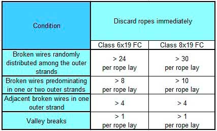
The number of broken wires is one discard criterion but not the only one. There could be cases in which there are no broken wires, but the rope must be discarded: for example, due to a reduction in diameter greater than 6% from nominal. Additionally, the ropes shall be discarded when there is red dust protruding from the outer strands, which is a clear sign of internal damage (fretting fatigue or corrosion).
It is interesting to note the last line of the table from ISO 4344, which reports that a single broken wire in the valley between one strand and another is a criterion for immediate discarding. This criterion is very important for wire rope inspectors to be aware of, since such evidence is a clear sign that the rope is losing the consistency of the core, and the outer strands are severely squeezed against each other. A thorough and deep analysis of the rope should be performed when this happens.
Small-Diameter Ropes and CSMs
The first task is to identify the most stressed portion of suspension means in which to look for discard evidence. Generally, this portion is near the traction sheave, when the cabin is on the most frequented floor (typically the ground floor).
Consider a reeving arrangement in direct suspension (1:1) with a traction sheave and diverter pulley (Figure 6). In this case, when the cabin is stopped at the ground floor, there is a portion of the suspension means, L, that will pass through the traction sheave and diverter pulley as soon as the cabin starts its travel upward. Considering that, in a residential building, almost 80% of trips start from the ground floor, there is strong evidence that this portion of the suspension means will be the most stressed area in which the discard criteria will begin to appear. For this reason, the inspection shall start from this point and then be extended to other portions and to the points in which the suspension means enters the sockets.
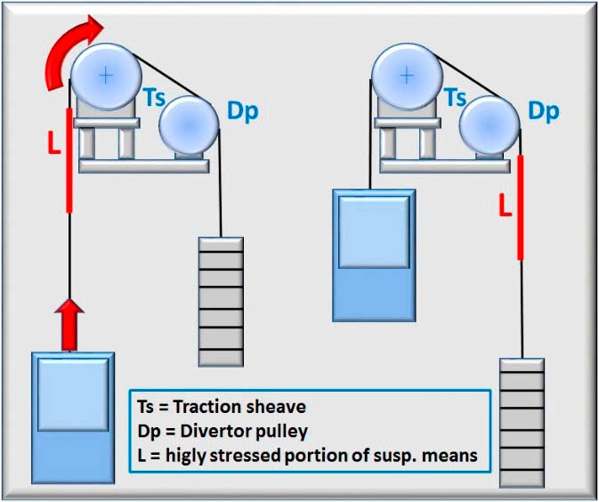
Despite the nature of the suspension element, irrespective of if it is coated, this principle holds validity and shall be used in general terms. Obviously, depending on the reeving arrangement of the specific elevator, the portion in question shall be shorter or longer, based on the number of pulleys over which the element will be bent more frequently.
The visual inspection will be first performed at a specific portion where deformation or surface abrasions could first be seen and pointed out. Following the initial visual inspection, it will be time to make a deeper analysis of the points identified to see if any broken wires are visible and if any wires are piercing the coating.
The care and maintenance instructions provided by the suspension media manufacturer should be followed, preceded only by what is reported in Annex E of ISO 4344. When in doubt, the advice of the manufacturer or a competent person should be sought.
Suspension Means Residual Life Estimation
For alternative suspension means, some new approaches have developed: a finite lifetime definition, a monitoring system with nondestructive technology or a combination of the two. To define the approach of the finite lifetime definition, it is important to create a laboratory experimentation in which a setup for simple and reverse bending is addressed. Figure 7 shows an example setup.
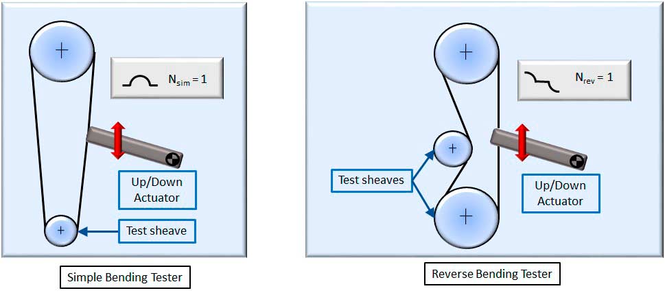
The suspension media shall be tested in combination with the expected traction sheave and deflection pulley, including the details of diameter and groove shape. An expected lifetime in service is calculated from the lifetime obtained by each element of the reeving arrangement by using a combination formula. Based on this calculation, a trip counter shall be installed on the elevator to monitor how much residual lifetime will remain for the system in operation. The counter installation should not be a direct replacement of periodic visual checks to ensure the system is in proper operating condition. Environmental factors or other reasons not anticipated could lead to damage of the suspension means and it reaching the discard point.
The second method by which to monitor the residual lifetime is by using a nondestructive methodology such as magneto- inductive, current flow, visual with webcams or by other means. As an example, let’s examine the magneto-inductive test.
The selection of this type of analysis is not because it is more suitable than the others, but because it is used extensively in similar fields like mining and aerial ropeways. The setup consists of a permanent magnet that brings the piece of rope under analysis into saturation. This means the rope is immersed into axially oriented magnetic flux lines. When an interruption of a section occurs, the magnetic flux lines are radially dispersed and detected by the detection coils (Figure 8).
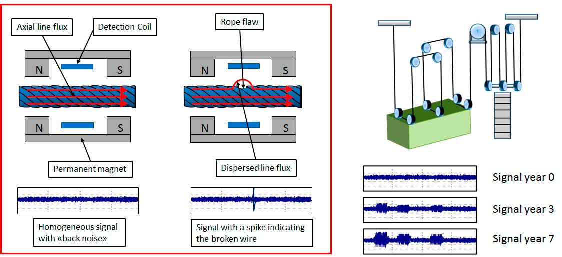
The magneto-inductive methodology is an evolutional type of exam in the sense that the signal will evolve as soon as the rope is subjected to more wear. The peaks become more and more accentuated as the fretting fatigue and internal abrasion continue. Evaluating the signals, some conclusions could be drawn on the state of the wire rope, and an expert could judge the situation. More importantly, the most stressed rope part is, in this case, put in evidence quite easily, and a visual check of this section should be conducted.
It is important to make an analysis at the time of installation and then to repeat the analysis year after year to see the evolution path of the diagram. In some cases, this device could be permanently installed on the elevator to monitor the situation in real time and to send notice to the maintenance company when there is a need for an in-depth inspection. This brings us to the matter of predictive maintenance that could be integrated with the suspension means at this point.
Using Suspension Means to Perform Predictive Maintenance Tasks
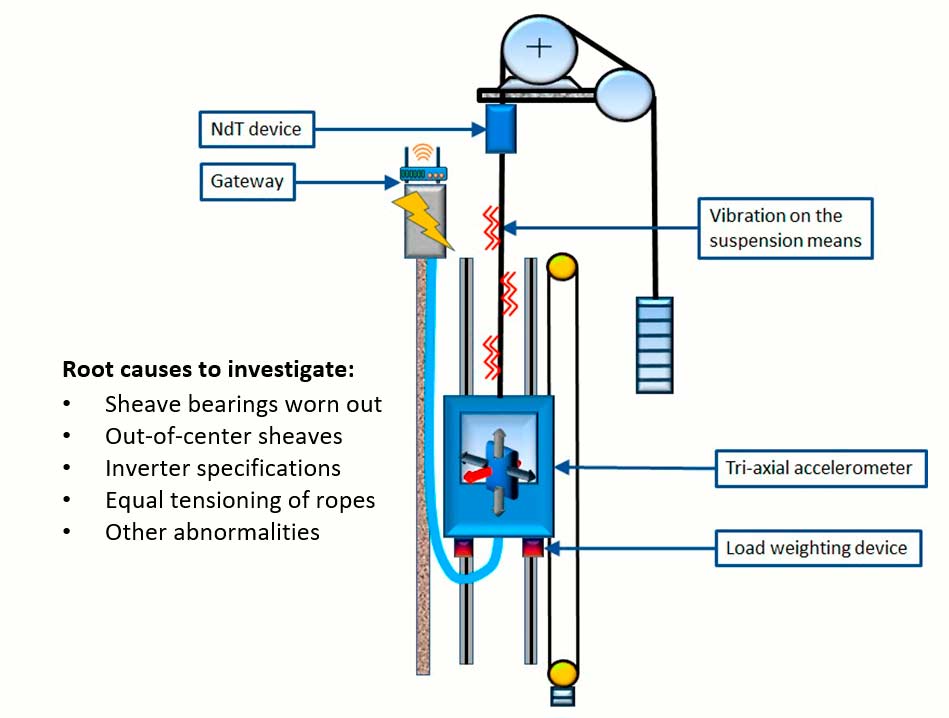
We will see now how to benefit from the sensors installed around the suspension means to get information to address predictive maintenance in the field. This will soon be realized in the industry. A basic set of sensors could eventually be composed as follows:
- A triaxial accelerometer: installed on the cabin, this will detect all the vibration connected with the travel of the elevator.
- A load-weighing device: this sensor will detect the load in the cabin and can also evaluate the vertical variation during the travel caused by bouncing or guide friction.
- A nondestructive testing device: installed close to the traction sheave, such a device can monitor the evolution on the wearing of the suspension means in real time. This could be based on any technology (e.g., magneto-inductive, current pulse, webcams, etc.).
- A gateway: to transmit the information gathered to a remote cloud where a specific algorithm will analyze the situation to draw conclusions on the quality of ride and eventual anomalies
The case analyzed is one in which the triaxial accelerator sensor is installed on the cabin and is detecting some vibration coming from the suspension means, even if the root cause could be coming from another part of the elevator system. Based on the frequency analysis and time measurement on the signal registered, the source of the problem can be determined. The maintenance company can therefore schedule a visit to the site knowing where to look, bringing the right spare parts for replacement.
Developing an algorithm that will understand the root cause from the vibration detected is a challenging process, but not impossible if the proper experimentation has been carried out.
Wearing of Suspension Means
Suspension means are subject to progressive wearing. If the frequency analysis put in evidence shows the vertical vibration has been slightly increasing over a specific time period and then suddenly experiences a peak in correspondence to the increased level of traffic, a visual check of the suspension media should be the first task performed. Visible discard criteria will likely not be present. By measuring the vertical bouncing over time, we can understand that the rope is under fretting fatigue before it contributes to ride discomfort.
Vibration Caused by the Rotating Mass
A completely different scenario is if the frequency of the vibration relates to the periodic amplitude that is somehow correlated with the traveling speed. In this case, the sheaves are the main elements to be investigated to understand if the phenomena are caused by roller bearings or by some other uniqueness of the rotary mass.
Equal Tensioning in Suspension Media
Another possible source of vibration could be from the set of ropes losing equal tensioning. In this case, the frequency has some parameter of causality but in correspondence to a specific location of the cabin in the shaft.
Effects of Inverter Parameters
Other vibrations affecting ride comfort can be attributed to the parameters of the inverter in piloting the motor. In this case, it is evident the vibrations in the cabin are amplified during acceleration and/or deceleration. Another element that could bring some variance here is the level of loading present in the cabin under such conditions.
Conclusions on Suspension Media Effects
As described above, upon seeing the suspension media vibrating, we could understand that we wouldn’t need to focus our attention on the suspension media itself. By analyzing the specific spectrum of the vibration frequency, we can obtain more characterization of the phenomena and look for the root cause from other elements of the elevator system.
Conclusions
This article should have made it evident how suspension means can contribute to the overall design of a complete elevator system, and in which way they can cooperate with safe operation and predictive evaluations. Furthermore, in specific conditions, the selection of the right suspension media for the right application could influence the total cost of ownership and the traffic management of the building.
A smart designer will start their own evaluation, taking into consideration the options that alternative suspension means could bring to their configurations.
This analysis has been limited to only a few aspects without entering into too much detail of the engineering cases. There is much more to be analyzed, and the suspension means are one of the main drivers for the innovation of a complete elevator package.
Nicola Imbimbo is the Global Applications manager for Prysmian Group’s Elevator & Escalator Business Unit. He began his career in the vertical-transportation (VT) industry as an apprentice for his family business, Imbimbo Ascensori, which was a FIAM elevator dealer at that time. He earned a degree in mechanical engineering from Polytechnic of Turin in 2001 with an experimental thesis dedicated to non-destructive monitoring of wire ropes. Upon graduation, Imbimbo served as a design engineer with an international manufacturer of specialty elevators. Prior to joining the Prysmian Group in 2011, Imbimbo worked as a technical application engineer with a few leading international companies involved in the production of wire ropes for lifting and transporting people.
Imbimbo is an active member of international working groups for the technical standardization of the elevator sector and has published numerous articles and delivered speeches at forums dedicated to VT. He is the co-author of a few books dedicated to elevator design and technical training and has trained operators, technicians and inspectors throughout Europe on rope-based systems designed for lifting and transporting loads and people.
In his spare time, he teaches training courses for the elevator industry as an independent consultant and is active on social network platforms where he publishes content related to the elevator and escalator sectors. Imbimbo is also the creator of the character “Nic The Elevator Guy®.”
Get more of Elevator World. Sign up for our free e-newsletter.


