An exploration into making elevators out of a variety of boxes, rubber bands, nails, screws and string
by Dr. Lee Gray, EW Correspondent
Recent events have had a dramatic impact on American and global society. Stay-at-home orders have shifted where and how we work and, regrettably, have affected many people’s ability to continue working. While the current situation has presented countless challenges, it has also resulted in positive shifts in behavior that are the result of people trying to figure out what they can do while “stuck at home.” There is, perhaps, an actual limit to the number of hours a person can sit on a couch and watch TV (even if you have Netflix). Fortunately, history provides some examples of how, in the “olden days,” we entertained ourselves. The patient readers of this column are now asked to find their inner child as we explore, from the perspective of the early 20th century, how to build model elevators.
In 1916, engineer William B. Stout (1880-1966) published The Boy’s Book of Mechanical Models.[1] The basis for the book was a series of newspaper columns Stout wrote, beginning around 1900, that were intended to educate young boys about engineering by building models of machines and mechanical devices. The articles were published under the pen name of Jack Kneiff, a name Stout selected because, allegedly, all you needed to build the models were simple tools, such as a jackknife (also commonly known as a pocket knife), hammer, screwdriver, etc. Stout’s book included a chapter devoted to model elevators, which featured illustrated instructions on how to build a “crank elevator” and a “hydraulic elevator.”
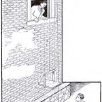
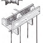
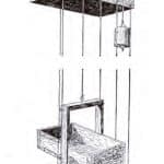
The crank elevator was, in essence, a simplified version of a winding-drum machine. The elevator was designed to carry messages or small items from the ground to a second-story window. The upper supports consisted of wood laths, and Stout’s instructions — clearly intended to terrify the builder’s parents — recommended that the supports be nailed to an exterior window frame (Figure 1). This framework held two “hoisting sheaves” made from wooden tape spools. A groove was carefully cut along the centerline of each spool to hold the hoisting string in place. Each spool was then fitted with a short wooden shaft that fit tightly into the center hole, with the shaft extending beyond the spool ends such that it almost touched the parallel lath supports. A bradawl was used to make holes in the lath slightly larger than the diameter of the small brads that were used to hold the sheaves in place (Figure 2). This construction allowed the sheaves to spin. Two screw eyes were also mounted on the upper framework. These served as anchors for the guide wires that directed the path of the car. A flat wooden base, also fitted with screw eyes for guide wires, was placed on the ground and held in place by wooden stakes (Figure 1).
The base also contained the crankshaft used to power the elevator. The crankshaft, placed at one end of the base and directly below a hoisting sheave, was held in place by two screw eyes and included a clever “brake” design. The builder cut a long notch into the end of the shaft and carefully pounded a nail into the base a few inches from and on center with the screw eye supporting the end of the crankshaft. When the operator wanted to hold the car in place, they simply pushed the shaft forward such that the nail entered the notch, which prevented the shaft from turning (Figure 3).
The builder was advised to wrap the hoisting string several times around the center of the crankshaft, after which it was passed up and over the hoisting sheaves and down to the car.
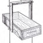
The design included two versions of an elevator car. The first, illustrated in the overall drawing of the model, was an open freight platform like those found in many factory or industrial settings (Figure 1). The second design, built using a cigar box as a base, resembles a stereotypical “boy’s model” of an elevator car (Figure 4). The builder simply attached the stiles and crosshead to the cigar box, and added screw eyes on the sides for the guide wires and a screw eye atop the crosshead for the hoisting string. “This elevator will furnish a lot of fun, and all that is required to make the car go up and down is the turning of a crank,” Stout proclaimed.
Stout’s design for a hydraulic elevator represented a remarkable translation of a water-balance elevator — one of the earliest and simplest hydraulic systems used in the U.S. — into model form. (For the history of the water-balance elevator, see the article series published in ELEVATOR WORLD, August-October 2017.) This model used the same cigar box elevator car built for the crank elevator. However, unlike the residential setting of the crank
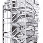
elevator, this system was illustrated in use on a fire stair in the rear yard of a four-story apartment building (Figure 5). The system’s critical components were a water storage “tank” (at the top of the system) and counterweight. Stout proposed the tank could be made from “an ordinary starch box of wood.” It is worth noting that, upon reading this description, your intrepid himself, “What’s a starch box?” It is, of course, a small wooden box designed to contain starch. Further research revealed such a box was fairly small; a typical example being approximately 6 in. high, 11 in. long and 7 in. wide. The model builder painted the inside of the box to create a waterproof container. The hoisting sheaves (wooden spools) were mounted on the side of the box, along with an automatic brake and screw eyes to anchor the guide wires. The wooden brake lever was carved to fit the curve of the center hoisting sheave and attached to a nail by a rubber band such that the band kept brake pressure on the sheave, which, in theory, prevented the car from moving. The brake was released by pulling on a string attached to the end of the lever. Although this was not mentioned in Stout’s description, the application of varying pressure on the brake via the release string would allow the operator to control the elevator’s speed (Figure 6).
The key to a water-balance elevator is, of course, the ability to add or subtract water from the counterweight, which, in turn, raises or lowers the car. Stout proposed the counterweight be made from a “tin can.” The builder first cut a short piece of metal tubing approximately 1/2 in. long. (Stout suggested the tube could come from “the handle of an umbrella or bicycle pump”). Next, a hole is carefully cut into the bottom of the tin can, and the tube is inserted such that it is half-inside and half-outside the can. The tube is then soldered in place. The next step involves using a large wood screw with a tapered head to make the seat for the valve stem. After carefully filing notches in the slanting portion of the tapered head, the builder inserts the screw into the top of the metal tube and “rotates [it] with a screwdriver while pressing down heavily on the screw. This will cut the edge of the tube at the same angle as the screw head so that when a new screw without the notches is put into the tube, we have a watertight valve” (Figure 7). A similar valve is installed in the starch box immediately above the vertical path of the counterweight. The final piece of the counterweight is a small wooden block placed inside the tin can such that it aligns with the water reservoir valve.
The operation of the elevator followed the exact method employed in a “real” water-balance elevator. If the car weighed more than the counterweight, it would descend to the bottom of the “shaft” and come to rest on the wooden base on the ground. Meanwhile, the counterweight would have ascended to the top, where the wooden block in the tin can would press upward on the bottom of the screw in the reservoir valve, allowing water to flow into the can. When the counterweight weighed more than the car, the operator would pull on the brake release string, and the car would ascend. When the counterweight reached the bottom, it would come to rest in a small trough designed to carry the water released by the upward pressure on the valve in the bottom of the can away (Figure 6).
The origins of Stout’s valve design are unknown. Its operation resembles a modern drip-stop valve (which allows removing the pot while the coffee is brewing without liquid leaking from the brew basket) in many coffeemakers. The key differences are that modern valves employ springs and washers to ensure a tight seal. Stout’s design relied on gravity, and, while it probably worked, it also probably leaked. However, this possible operational deficiency does not lessen the ingenuity of the valve design and the other skill evident in the design of both models. When his book was published, Stout was a young engineer at the beginning of what would be a remarkable career. He went on to become a leading automotive and aeronautical engineer; his numerous designs included the well-known Ford Trimotor airplane.
When reading Stout’s descriptions of these model elevators, in addition to puzzling over simple things like starch boxes, your author wondered if it would be possible to recreate these designs in a way that would replicate the original intent. Several years ago, I was able to pursue a similar investigation regarding a toy escalator (“All I Want for Christmas is a Meccano Moving Stairway,” EW, December 2017). However, that effort simply required the acquisition of several sets of antique toys. Given the materials involved in building Stout’s models, this was a different type of challenge. Fortunately, in the 21st century, we have a remarkable research tool literally available at our fingertips. I am, of course, talking about eBay.
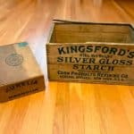
Within a month of buying Stout’s book, I was the proud owner of a set of vintage starch and cigar boxes (Figure 8). If all goes well, the publication of the conclusion of this two-part article (which examines another author’s approach to building model elevators in the early 20th century) will include images of a cigar box elevator car and hydraulic-elevator reservoir (complete with brake) as next month’s Online Extras. As is, I hope, evident in all my articles, I always have fun with my research and love what I do.
- Figure 1: Crank elevator: installation[1]
- Figure 2: Crank elevator: hoisting sheave and overhead framework design and construction[1]
- Figure 3: Crank elevator: crankshaft design and construction[1]
- Figure 4: Cigar box elevator car: design and construction[1]
- Figure 5: Hydraulic elevator: installation[1]
- Figure 6: Hydraulic elevator: details of water tank and base design and construction[1]
- Figure 7: Hydraulic elevator: details of counterweight and valve stem design and construction[1]
- Figure 8: Vintage starch and cigar boxes awaiting their transformation into model elevator components
Reference
[1] William Bushnell Stout. The Boy’s Book of Mechanical Models, Little,
Brown, and Co., Boston (1916).
Get more of Elevator World. Sign up for our free e-newsletter.
