Delving into another author’s approach to building model elevators in the early 20th century
by Dr. Lee Gray, EW Correspondent
The first part this article series explored how to build model elevators from the perspective of the early 20th century (ELEVATOR WORLD, June 2020). This exploration began with an examination of models designed by engineer William B. Stout (1880-1966), which were published in The Boy’s Book of Mechanical Models (Boston: Little, Brown, and Co.). The conclusion of this investigation, which is intended as a gentle distraction from our current challenging situation, examines the work of architect A. Neely Hall (1883-1959).
Like Stout, Hall began his career writing weekly newspaper columns. However, whereas Stout focused on introducing young boys to the world of engineering through building models of machines and mechanical devices, Hall embraced a wider scope of project types, ranging from toys to furniture. A collection of his writings on toy designs was published in 1915 as Home-Made Toys for Girls and Boys.[1] The work of these contemporary authors (Stout’s book appeared in 1916) and their different professional backgrounds — engineer versus architect — allow for an interesting comparison.
Hall’s architectural background is immediately evident in the proposed settings for his elevators, which included a dollhouse and a model office building. He also employed a different approach to the design of the elevator car. While both began with a cigar box, Hall’s design more closely resembled an actual elevator car, whereas Stout had pursued a more utilitarian scheme suited to the outdoor settings imagined for his designs. (See this month’s Online Extras at elevatorworld.com for a reconstruction of his car design.)
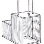
The materials list for his dollhouse elevator included “two small pulleys, 4 ft of brass chain, 6 ft of No. 12 wire, half a dozen double-pointed tacks or screw eyes, a short piece of lead pipe and a cigar box.” The brass chain, doubtless chosen for its decorative character, as it would have been visible, served as the hoisting rope and connected the car to the counterweight. The chain ran through two pulleys or sheaves located at the top of the shaft. The wire formed the “guide rails” and ran through pairs of double-pointed tacks or screw eyes placed on the sides of the car. Hall gave the cigar box a vertical orientation, with the opening
corresponding to the elevator door. He stated that the box should be “cut down,” such that the final dimensions were 2.25 in. wide, 3.75 in. deep and 7 in. high. While cigar boxes come in a wide variety of sizes, Hall’s proposed car size would have required a substantial transformation of most cigar boxes. For example, the vintage cigar box purchased for the reconstruction of the Stout elevator car is 9 in. long, 5.25 in. wide and 2.25 in. deep.
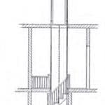
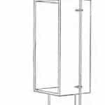
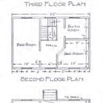
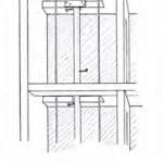
Hall provided two drawings that depicted his dollhouse elevator: a perspective view and a front elevation (Figures 1 and 2). The elevation clearly indicates the narrow car door opening, and the perspective drawing depicts the design’s essential components (and included, for unknown reasons, a detail drawing of a pulley). Both drawings include an odd cylindrical feature on top of the car. This was a small piece of lead pipe that had cosmetic and utilitarian purposes. The pipe concealed the screw eye, to which the hoisting chain was attached, and added weight to the car. The latter feature was important because of the lightweight nature of most cigar boxes. (The vintage cigar box used in the reconstruction of the Stout elevator car weighs only 5.5 oz.) Thus, the added weight helped hold the hoisting chain firmly in the sheave grooves. The lead-pipe counterweight was to “be just heavy enough to make a perfect balance between it and the car.” The elevator was also carefully depicted on the dollhouse plans; it was in the stairwell, a normative residential placement (Figure 3).
Hall’s elevator system, designed for use in a model of a six-story office building, was described as a “unique mechanical toy well worth one’s making.” The elevator’s operation was also described as “magical”:
“Release the little car at the top floor, and it will descend to the ground floor, and then return to the starting point, without you having to touch it a second time. A magical elevator? Perhaps so. A little mechanical device performs the trick.”
Interestingly, this description was, in fact, the opposite of what actually happened with Hall’s design. Whether this was an error in editing or writing is unknown. Hall’s design permitted, in theory, the car to start at the first floor and automatically ascend and descend — a movement pattern more logical in its depiction of normative elevator operation.
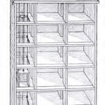
The model office building was built using a “packing case,” with wooden floorplates inserted in it. The elevator “shaft,” consisting of cutouts in the floorplates, was located at one end of the packing case (Figure 4). The overall scale of this model resulted in a much smaller car, made from cigar box wood, which was only 3 in. wide, 2.5 in. deep and 4 in. high. The car’s proportions and vertical orientation closely resembled a typical elevator car. However, this “normative” car also featured a rear compartment that was 3 in. wide, 2 in. deep and 2.5 in. high.
Both the car and rear compartment were mounted to a wood base (Figure 5). The guides were, again, made of wire; however, in this design, Hall was far less prescriptive regarding the type of wire required, stating instead that “bell-wire, or almost any wire that you have on hand, will do.” Surprisingly, the guide wires were placed inside the car, running through holes drilled in the ceiling and floor. The hoisting rope was described as a “cord,” and, in place of the pulleys employed in the dollhouse, it ran over wood thread or tape spools, which Hall described as “pulleys or sheaves.” The counterweight was a small bottle filled with sufficient sand to make it weigh more than twice as much as the car. The counterweight ran inside a “smokestack” made from a cardboard mailing tube, which was attached to the packing case with wire straps and guide wires at the top (Figures 4 and 6).
Hall also designed a simple control mechanism. This consisted of a stick or dowel, which could be made from a “broom handle, curtain pole or flagstaff.” The dowel was placed at the rear of the shaft, extended from the bottom to topmost floorplate and installed such that it could rotate. Nails were driven into the dowel on alternating sides at heights matching the floor levels. A control string was wrapped around the base of the dowel, with the string ends attached to control levers (Figures 5-7). Pulling down on a lever caused the shaft to rotate, placing a nail in the car’s path and stopping its movement.
The car’s rear compartment was a critical feature of the system’s “magical” operation. Another critical component, described by Hall as “ballast,” was a small bottle filled with enough sand such that it weighed more than the combined weight of the car and counterweight. The ballast bottle featured a cork with a screw eye, which allowed it to be suspended from a hook-and-eye at the top of the shaft. The hook-and-eye was also attached to a rubber band (Figures 7 and 8). The first step in the car’s automatic operation was to lower the car to the first floor (by hand) and rotate the controller such that car could not move. The next step was to hang the ballast bottle from the hook-and-eye. The operator would then rotate the controller to release the car, which rose swiftly up the shaft. According to Hall:
“With the hook and rubber band properly adjusted, this is what happens when the car ascends to the top of the shaft. The bottom of the rear portion of the car strikes the bottle, lifts it enough to release the end of the hook, and the rubber band springs the hook out of the way. The bottle remains upon the rear portion of the car, and its weight carries the car to the bottom of the shaft.”
Presumably, the rise and fall of the car could be stopped by the action of the controller, assuming the operator could pull the lever fast enough to catch the car before it reached the top (or bottom) of the shaft.
Hall, like Stout, is believed to have built working models of his toys as an important part of his creative process. However, in this case, the design appears to have several flaws that should have been apparent during test runs of the elevator’s automatic operation. The drawings depict the hoisting rope attached to the car such that it was slightly off-center and closer to the car entrance. This placement, coupled with the added weight of the ballast in the rear compartment, would have caused the car to tilt backward during its descent. This tilting action would have flexed the guide wires, which would have slowed the car’s speed and possibility halted its movement. An additional, more serious problem involved the shaft openings. The suggested shaft size was “about 5 in. square.” The car and rear compartment were 3 X 4.5 in. Thus, the tilt could have easily resulted in the car striking the sides of the shaft openings. However, these potential operational flaws do not detract from an ingenious attempt to design a magical toy.
As mentioned in the beginning of this article, this investigation into Stout’s and Hall’s model elevator designs was prompted in large part by a desire to explore and present an aspect of elevator history capable of, if only for a brief time, shifting our attention away from the current challenges. Of course, your author’s interest in vertical-transportation toys has been explored in the past, such as in “All I Want for Christmas is a Meccano Moving Stairway” (EW, December 2017). The contrast between these types of toys is intriguing: Meccano was a precursor to the modern ERECTOR Set, while Hall and Stout designed homemade or handmade toys. While both approaches required imagination and hard work to achieve results, the former also required sufficient economic means to acquire the necessary components. In theory, Stout’s and Hall’s designs could be built relatively cheaply using found or discarded materials (packing crates, old cigar boxes, etc.). These combined historical explorations — coupled with spending a reasonable amount of money on eBay (all, of course, justified as “research expenses”) — have allowed your author to assemble a wealth of early 19th-century resources that can be used to explore model elevator and escalator systems. Now, if I only had more time to play with my toys.
- Figure 2: Perspective view of dollhouse elevator[1]
- Figure 3: Dollhouse plans[1]
- Figure 4: Overall perspective view of office-building elevator[1]
- Figure 5: Car design for office-building elevator[1]
- Figure 6: Section view of office-building elevator[1]
- Figure 7: Perspective view of office-building elevator[1]
- Figure 8: Detail of ballast and self-lowering device in the office-building elevator[1]
Reference
[1] Hall, A. Neely. Home-Made Toys for Girls and Boys, Boston: Lothrop, Lee
& Shepard Co. (1915).
Get more of Elevator World. Sign up for our free e-newsletter.
