Lifts Without Ropes: How Many Shafts and Cars Are Needed?
Jan 1, 2016
Your authors establish traffic-design principles and describe dispatching and modeling strategies related to future systems.
by Stefan Gerstenmeyer and Dr. Richard Peters

This article was first presented at the Fifth Symposium on Lift & Escalator Technologies, www.liftsymposium.org.
A new generation of lifts currently under development applies magnetic linear propulsion and does not need ropes. Shafts are shared, and lifts move in two or more dimensions. Taller and more densely populated buildings will be accommodated by adding more cars but not necessarily more shafts. Engineers planning lift installations need new ways to assess the handling capacity and quality of service provided by ropeless elevators. In this article, some traffic design principles are established by applying simple cycle time calculations. For example, shuttle lift applications are considered and compared with current roped solutions. Improving on cycle time calculations requires the development of dispatching strategies, the modeling of safety distance requirements and traffic-simulation models. An overview of progress in these areas will be presented.
The number of roped lifts in known lift systems is limited to one or two cars in one shaft as the suspension ropes of the lower car need to be diverted around the upper car.[1] Putting more than two cars in one shaft is limited because of the space needed by the ropes. Furthermore, traffic-handling efficiency is limited by putting more than two cars in one shaft, as it becomes more difficult for all cabins to serve the main entrance floors. Using a shaft for both up and down travel means that the cars need to wait until all of the cars need to reverse their direction of travel, which is a constraint to improving performance. Having multiple cars running in at least two shafts circulating with one shaft being used for traveling in the up direction and the other shaft for traveling in the down direction enables improvements in performance and efficient shaft usage. An early example is the paternoster, which was the first realization of a circulating lift system.[2] The continuous, slowly circulating chain of open cabins, with no cabin or shaft doors, has limitations in traveling time, safety and transportation of handicapped passengers. Assuming a cabin-to-cabin distance of 3 m, a velocity of about 0.3 mps[3] and two passengers per cabin, the handling capacity of a paternoster is about 60 passengers per 5 min.
For new and safe circulating multicar lift systems (MCLSes), linear motors installed in the shaft lifting multiple individual and independent cars are among the main enabling technologies. The concept and idea of a circulating MCLS with independent moving cars is not new in the lift industry.[4] Simple traffic calculations of a circulating lift system were published based on technical assumptions, as there were unanswered technical and economic questions.[5] Technical challenges of using lifts without ropes/counterweights and opportunities in building efficiency for circulating lift systems were discussed.[6] Advanced two-dimensional traffic systems that include horizontal passenger movement were also analyzed.[7 and 8]
In 2014, an MCLS currently under development was unveiled.[9] Different technical innovations and solutions solve technical challenges to realize a circulating MCLS.[10] Linear motors propel multiple independent moving cars in multiple shafts. Lightweight cabin designs for eight passengers enable an economical system. A certified safety system, including safety brakes, ensures that there is no collision. A backpack solution guides cars and enables exchanger units to move cars between shafts horizontally. This article will examine traffic analysis of this realistic system based on simple cycle time calculations and describe constraints of the cycle time.
Traffic Concept
With intercity trains and urban transportation, different horizontal-transportation systems exist and are linked together as a horizontal-transportation concept. Compared to horizontal transportation, a circulating MCLS needs to fit into a vertical traffic concept of a tall building.
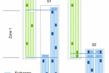
A circulating MCLS is used as a shuttle lift system between ground and sky lobbies within a vertical traffic concept.[10] Exchanger units are installed in the ground lobbies and upper sky lobbies. Figure 1 shows examples of how a circulating MCLS can be included in a vertical-transportation concept. Different MCLSes (S1) serve the sky lobbies of different building zones (zones 1 and 2). The local transportation within the building zone can be provided by traditional lift systems, e.g., machine-room-less systems (L1 b) or by systems with two independent cars in one shaft (L1 a). The latter solution enables direct interzone traffic. MCLSes with double ground lobbies and double sky lobbies (S2) enable simultaneous loading of two cabins in a shaft. Local groups can be realized with double-deck elevator systems (L2 b) or with more flexible systems with two independent cars in one shaft (L2 a). Horizontal transportation of passengers is also possible but not considered in this article.
Minimum Possible Cycle Time
The number of passengers arriving at a specific lobby that can be transported by the MCLS within a specific time can be calculated by the number of departing full cabins. The time between two subsequent cars is the cycle time.
Cycle Time
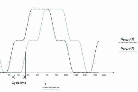
The cycle time in an MCLS is the time between the departure or arrival of two subsequent cars. It also can be defined as the time between two subsequent cars passing a specific position in the shaft traveling at the same speed and in the same direction.
Figure 2 shows the vertical positions over time of two subsequent cars, DVCar1(t) and DVCar2(t). Both cars are traveling in the up direction in the first shaft, changing shafts at the top floor at 100 m and traveling in the down direction in a second shaft. While car 1 has already changed to the down-direction shaft, car 2 is arriving at 100 m in the up-direction shaft. At the bottom floor, the cars are changing shafts again. Both cars are stopping in each direction at an intermediate floor at the 50-m level. The time between cars 1 and 2 is the cycle time.
For a better overview, the position of additional cars traveling in the MCLS is not shown. As the minimum possible cycle time is limited by the minimum distance during a complete round trip of the cars, critical situations need to be considered in detail. It is obvious that only one car can be at a specific position at the same time. If cars are traveling, they are changing position continuously, making the position available for the next car. If cars are standing, only one car can be at that position for the time the car is located at that position. To find the minimum possible cycle time over a complete round trip, the stops of the cars need to be analyzed in detail.
Safety Distance Constraints
To define the minimum possible cycle time between cars in an MCLS, safety distance constraints need to be considered. There must be a minimum distance between cars at any time during normal operation. The control system responsible for an optimized handling capacity in 5 min. (HC5) and quality of service needs to consider this minimum distance. A certified safety system triggers an emergency stop of the cars in case of violation of safety distances. In addition, by enabling a controlled stop of the cars, the control system monitors positions and movements of the cars and decelerates cars in unexpected situations without triggering the emergency stop. The controlled stopping of cars includes the same or higher jerk and deceleration rates than normal operation rates.
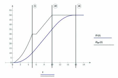
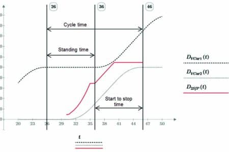
A stopping distance and a stopping point of the controlled deceleration can be calculated at any time.[11] In case of violating any minimum distances between cars, the cars can be stopped by executing controlled deceleration. Figure 3 shows the position of a car over time (D(t)) and the stopping point (DSP(t)) after a spontaneous controlled deceleration with rated deceleration values. If the lift is in the deceleration process to the 50-m level (10-16 s.), the spontaneous controlled deceleration cannot stop the car earlier if the rated values for deceleration and jerk are used. The stopping point is also constant if a spontaneous deceleration is started during the end of the acceleration process (5-6 s.), while the acceleration is reduced by a negative jerk. The controlled deceleration can also be operated with higher values for deceleration and jerk. To calculate a safe position of another car, a minimum distance, which includes the car height, needs to be added to the stopping position.
Exchanger
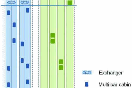
To analyze the stop at an exchanger unit, the design of the exchanger unit and the process of exchanging cars between shafts needs to be considered. The analysis is based on a backpack solution including the linear motor and car guidance.[10] The shaft elements are able to rotate by 90°. Cars can move horizontally. Passengers can load and unload during the rotation process since the cabin is held in an upright position. Figure 4 shows a simple example of the functionality of the exchanger unit.
Calculation of the Minimum Possible Cycle Time
Situations involving the bottleneck during the minimum possible cycle time (tCy) are analyzed. This includes the stops at the exchanger units and intermediate stops where both cars are stopping successively.
Cycle Time at an Exchanger Landing
The minimum cycle time at an exchanger landing (tCyEx) with passengers loading and unloading can be calculated with Equation 1. The passenger transfer during the standing time (tStand) of the cabin can be done in parallel to the exchanger preparation time tEx (rotation of the shaft element) for the following horizontal or vertical movement:
tCyEx=tArr + max (tStand, tEx) + tDep + tEx (Equation 1)
After a previous/front car has departed from the exchanger unit (tDep), the next car arrival time (tArr) is the time it takes a car to arrive after the exchanger unit has been prepared for the next car (tEx). A long car arrival time (tArr) for the next car may enable the parallel preparation of the exchanger after the previous/front car has departed the exchanger landing.
The standing time (tStand) is calculated with Equation 2 and includes passenger transfer times (tp), average number of passengers in the car (P) and door times (door open time: to, door dwell: tdwell, door closing time: tc).
tStand = to + tdwell + tc (Equation 2)
Cycle Time at an Intermediate Floor (Both Stopping)
The minimum cycle time at an intermediate floor with two subsequent cars stopping at the same floor (tCyF2) can be calculated with Equation 3. The time between departure of the front car 1 and the arrival of the following car 2 (start-to-stop time ts2s) depends on the stopping distances and minimum distances between cars and is shown in Figure 5. The safe position for car 1 related to car 2 is shown with D2SfP(t) and depends on the position, stopping point of a controlled deceleration with rated values of car 2 and an additional minimum distance between car 2 and car 1. The safe position must not touch the position of car 1.
tCyF2 = tStand + ts2s (Equation 3)
tCy = max (tCyEx,tCyF2) (Equation 4)
The situation with the longest minimum cycle time is the minimum possible cycle time of the MCLS and is defined with equation (4).
Handling Capacity
To use a circulating MCLS in a vertical traffic concept, it is necessary to know the HC5. As this lift system is different than traditional ones, the known equations need to be adapted to the new system.
General
The handling capacity for incoming passengers can be calculated with the simple equation for conventional lifts using the interval (INT) and number of passengers per cabin (P) (Equation 5).[12] This is also true for a circulating MCLS.
![]() (Equation 5)
(Equation 5)
The interval (INT) of a group of circulating MCLS is defined by the average cycle time (tCy) and the number of MCLSs (NS):
![]() (Equation 6)
(Equation 6)
The handling capacity for incoming passengers in an up direction is independent from any down traffic or traffic between upper floors (e.g., sky lobbies). Additional down traffic will affect the round trip time (RTT) of a cabin because of passenger transfer times and door times of existing or additional stops. If the RTTs of the cabins change, the number or speed of cabins needs to be adapted accordingly in order to keep the average cycle time between subsequent cars to a constant value.
Cabin Size
Increasing the cabin size will increase the handling capacity, especially in shuttle applications. However, in shuttle applications, the HC5 is not a linear function of the cabin size. Doubling the cabin size does not double the HC5 as passenger transfer times and cycle times increase.
Double Entrance
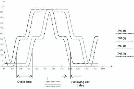
As handling capacity is limited by the passenger loading and unloading times, double entrance lobbies (two lobbies above each other) enables simultaneous loading of two cabins, which increases handling capacity. For a circulating MCLS, each entrance level may have an exchanger unit enabling a parallel exchanging of two cars. The cycle time is now measured between two pairs of cars (Figure 6); therefore, double the number of passengers can be transported per cycle time. Cycle time will increase slightly, since the arrival and departure times of two cars at a double lobby/floor are longer compared to those of a single car stopping at a single floor.
Number of Cabins
The number of cabins (NC) in a circulating MCLS depends on the RTT and the cycle time (tCy). It can be calculated with the following equation:
![]() (Equation 7)
(Equation 7)
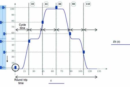
This is also illustrated with Figure 7. It shows a complete round trip of a car (D1(t)). The RTT is divided by the cycle time and shows every position of the car after a period of the cycle time. These positions equal the current position of the other cars in the MCLS at time t = 0, which is shown with the two shafts of an MCLS in Figure 7. With double entrance configurations and pairs of cars, the number of cars is doubled.
It is only possible to put an integer number of cars into the system. In case of an unchanged RTT and rounding down the number of cars (the result of Equation 7), the real average cycle time (tCyR) will be higher than the minimum possible cycle time (Equation 8). To achieve the same handling capacity, the RTT needs to be reduced (e.g., by increasing the speed of the cars).
![]() (Equation 8)
(Equation 8)
In case of rounding up the number of cabins (the result of Equation 7), the average minimum possible cycle time cannot be reduced because it is limited to a minimum. The RTT needs to be increased according to Equation 9 to avoid traffic jams (e.g. by reducing the speed of the cars):
RTT = NC * tCy (Equation 9)
Quality of Service
As the major measure of quality of service is waiting time, the waiting time derived from the cycle time and interval may be the main measure.[12] However, traveling times and the number of stops also need to be considered. In multicar applications, additional delays may be included as quality measures.[13]
The maximum HC5 for conventional roped elevators is achieved in a two-stop shuttle application. The RTT is kept to a minimum. Using RTT calculations, the quality of service, interval and waiting time can be optimized.
For a circulating MCLS, the HC5 is independent from the number of stops. In addition, the waiting time – e.g., in the main entrance – can be kept to a minimum, but additional delays during the journey will affect quality of service. In applications where all cabins have the same stops, these additional delays can be reduced to a minimum or completely avoided through synchronization of the cars. This can be compared with an underground train for urban transportation.
Every train of a specific line has the same stops with a similar stop time. If one train cannot pass another train, additional delays can be avoided during normal operation of the system.
Allowing individual stops for each car limits the options to avoid these delays without sacrificing HC5, as cars cannot pass each other. More sophisticated controls allocating passengers to cars can help improve the situation. This requires advanced passenger guidance, good indication and passenger awareness that cars loaded from the same landing door travel to different destination floors. This is unexpected by most lift passengers and could be confusing; it may be an option in the future.
Therefore, the shuttle application with one or multiple sky lobbies is preferred, as it ensures good quality of service with maximum possible handling capacity.
Comparison of Shuttle Lift Systems
Consider an MCLS when compared to traditional double-deck lift systems in a shuttle lift application. Figure 8 shows the compared configurations. The comparison is based on the cycle-time calculations for the MCLS and RTT calculations for the double deck system. Different travel heights will be compared: 100, 200, 300, 400, 500 and 600 m.
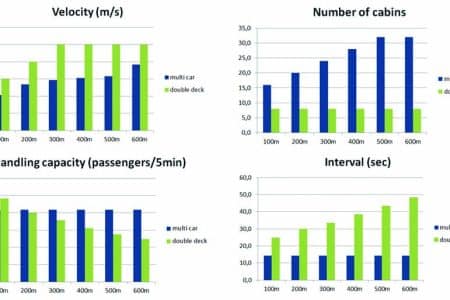
Table 1 shows the parameters of both systems. The traffic split is 80% incoming and 20% outgoing passengers equally distributed to both lobbies. Figure 9 shows the chosen velocity and number of cabins, and the HC5 and interval depending on travel height.
The handling capacity of the multi car system is constant and independent from the travel height. Starting with a travel height of about 200 m, it is going to be higher than that of the compared double-deck system. The benefit of the circulating MCLS can be seen with increasing travel height. To keep the handling capacity constant at the MCLS for every travel height, the number of cabins rezCxzCquired needs to be adapted for the MCLS without additional shafts. Without adding any shafts, the number of cabins for the four double-deck shafts is constant.
With increasing travel height, the rated velocity is increased for both systems. The velocity of the MCLS is lower than the velocity of the double deck.
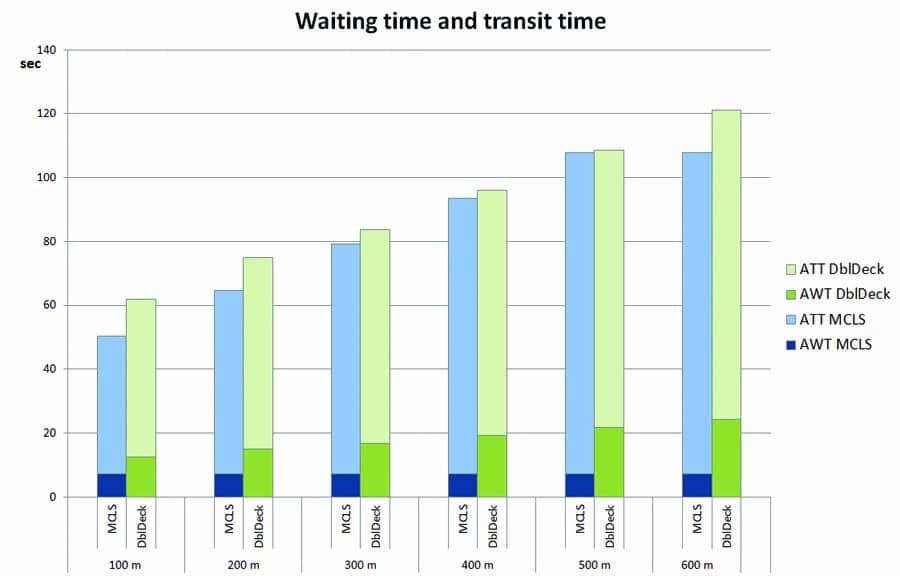
The average waiting time (AWT) and average transit time (ATT) of both systems is compared in Figure 10. The relationship between interval and waiting time is complex.[14] For simplicity, in these results, the AWT of RTT calculations is taken as 50% of the interval.
Since the interval of the multi car is constant, the AWT is also constant. Although the chosen velocity of the multi car is less than that of the double deck, the time to destination of the MCLS provides better values. This is caused by lower AWT and shorter passenger loading/unloading times.
Conclusion
Handling capacity for a circulating MCLS is based on the minimum possible cycle time of the system, which is discussed and defined in this article. If the average RTT of an MCLS increases, the number of cars has to be adapted to keep the minimum possible cycle time and a constant handling capacity. To achieve the minimum possible cycle time without traffic jams, the velocity is also adapted. Safety distances and stopping distances need to be calculated and considered to calculate reasonable values for the minimum possible cycle time. Based on cycle time and RTT calculations, a circulating MCLS and a double-deck system are compared with different traveling heights in a shuttle application. The MCLS provides constant values for handling capacity and AWT with increasing traveling heights by adding more cars to the system. Also, short cycle time enables short AWTs. These values need to be proven by simulation. Advanced control algorithms may also enable additional MCLS applications.


References
[1] Thumm, G. “A Breakthrough in Lift Handling Capacity,” Elevator Technology 14, Proceedings of Elevcon 2004, International Association of Elevator Engineers (IAEE), 2004.
[2] ELEVATOR WORLD. “The Elevator Museum – Timeline,” theelevatormuseum.org/timeline.php, 2015.
[3] Strakosch, G. and Caporale, R, The Vertical Transportation Handbook, Fourth Edition. John Wiley & Sons, Inc., Hoboken, New Jersey, 2010.
[4] “An Elevator Go Round,” ELEVATOR WORLD, Vol. XLII, January 1996.
[5] Jappsen, H. “High Rise Elevators for the 21st Century,” Elevator Technology 12, Proceedings of Elevcon 2002, IAEE, 2002.
[6] Godwin, A. “Circular Transportation in the 21st Century (Without the ‘Beautiful’ Counterweight!),” Elevator Technology 18, Proceedings of Elevcon 2010. IAEE, 2010.
[7] So, A., Al-Sharif, L. and Hammoudeh, A. “Analysis of Possible Two Dimensional Elevator Traffic Systems in Large Buildings,” Elevator Technology 20, Proceedings of Elevcon 2014, IAEE, 2014.
[8] So, A., Al-Sharif, L. and Hammoudeh, A. “Traffic Analysis of a Simplified Two-Dimensional Elevator System,” Building Services Engineering Research and Technology.
[9] ThyssenKrupp Elevator AG. “New Era of Elevators to Revolutionize High-Rise and Mid-Rise Construction,” urban-hub.com/ideas/new-era-of-elevators-to-revolutionize-high-rise-and-mid-rise-construction, 2014.
[10] Jetter, M. and Gerstenmeyer, S. “Next Generation Vertical Transportation System” submitted article to CTBUH 2015 New York Conference Proceedings, New York, 2015.
[11] Gerstenmeyer, S. and Peters, R., “Safety Distance Control for Multi Car Lifts,” research article, draft, unpublished, 2015.
[12] The Chartered Institution of Building Services Engineers. CIBSE Guide D: 2010 Transportation Systems in Buildings, London, 2010.
[13] Smith, R. and Gerstenmeyer, S. “A Review of Waiting Time, Journey Time and Quality of Service,” Symposium on Lift and Escalator Technologies, Northampton, U.K., 2013.
[14] Peters, R. “The Application of Simulation to Traffic Design and Dispatcher Testing,” Symposium on Lift and Escalator Technologies, Northampton, U.K., 2013.
Get more of Elevator World. Sign up for our free e-newsletter.

