Low-Voltage Storage for Energy-Intelligent Elevators
Jan 1, 2019
An examination of current and future ultracapacitor and battery technology shows how any small or medium-sized elevator manufacturer can offer high-end solutions with minor investments.
by Dr. Estanis Oyarbide, Luis Jiménez, Dr. Pilar Molina Gaudó, Logan López, Rubén Gálvez and Dr. Carlos Bernal Ruiz
The elevator industry is moving toward finding new solutions for energy management. Examples of such are energy recovery systems based on local storage in ultracapacitors, battery-powered elevators for peak power mitigation and improved uninterruptible- power-supply (UPS) operation, solar and/or wind powered elevators, among others. Most of these new concepts include energy-storage systems, so they require batteries and/or ultracapacitors, depending on the energy to be stored and the power cycling profile. In fact, both batteries and ultracapacitors are low-voltage technologies, whereas elevator traction systems are based on well-known three-phase industrial AC drives operating at high voltage levels of around 600 V (or 400 V in some countries) at their DC bus. One of the possible solutions consists of the serialization of many basic cells until industrial voltage levels are reached. This solution, though apparently simple, is not practical, because it is expensive, and safety and reliability problems are multiplied. Thus, a practical energy storage system for elevator applications should operate at around 48 V, which is a safe, commercially standard and cost-effective voltage level.
Some modifications are required if a 48-V energy source must be integrated in an elevator traction system. There are two possible options. First, (bidirectional) DC/DC converters can be used interconnecting low-voltage 48 V to conventional elevator traction systems at 600 V. Second, the entire traction system can be redesigned to operate at 48 V. This article shows the technical challenges of the integration of low-voltage energy storage systems in elevator traction systems. Issues related to efficiency, cost, availability of required parts for production, flexibility of use and others are analyzed. This way, it is possible to identify the key challenges and the best-suited solutions in each case.
Applications of Energy Storage
Small UPS systems are very common in most installations. The UPS normally keeps the control alive, while the elevator moves to the next stop in the most favorable direction. They are broadly used and still pose the challenge of state-of-health (SoH) of the battery pack. But, these are not enough to add energy intelligence features to new or existing elevators. Recently, customers have been demanding products that turn around local energy storage ability, and elevator manufacturers are providing solutions.[1-4] Standard energy storage devices are primarily based on chemical batteries, and, therefore, elevators with electrical traction systems are the ones best suited for this type of adaptation. Ultracapacitor technology is relatively new, but its advantages in terms of number of cycles and power density make it ideal for applications that require many high-power charging and discharging cycles.[6-10] Some application examples with batteries and ultracapacitors follow.
Extended UPS Operation
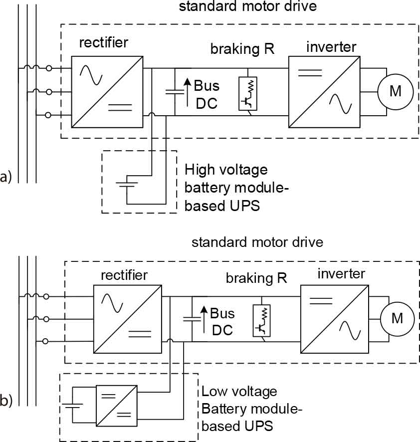
Some customers require keeping the operation of the elevator even under long-term line blackouts. Among other solutions, an easy way out is to connect a battery module to the DC bus of the inverter (Figure 1-a). Typical operating voltages are around 600 V, so many batteries must be serialized, which leads to an oversized energy storage capability. Moreover, special safety and battery management circuitry must be included, making a practical but expensive solution. In the same way, due to the fast aging of batteries, operation costs are incremented. Another solution is just to interconnect a set of low-voltage batteries with the high-voltage DC bus through a DC/DC converter (Figure 1-b).
Peak Power Mitigation
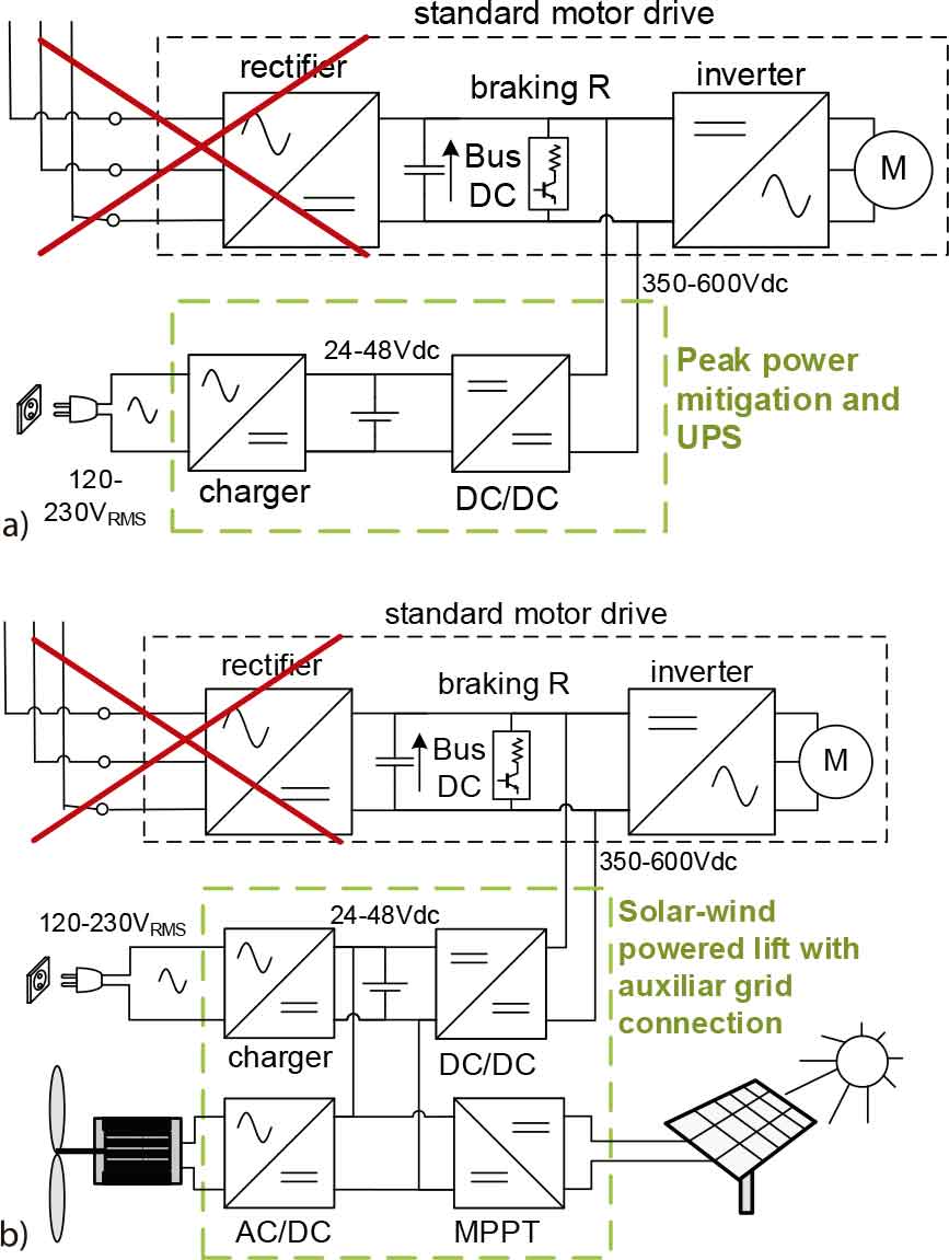
Electrical consumption by elevators is characterized by cycles of high power peaks during acceleration or deceleration and (typically) half the peak power during steady travel. The peak power determines the installation and operation costs of the connection to the grid. The peak value could be one order of magnitude higher than the average power. This fact is particularly relevant for residential elevators, in which, due to the low number of travels, the total amount of required energy is very low. Installation and operation costs could be reduced if the elevator is fed from a set of batteries permanently charged from the grid at a very low peak power rate (Figure 2-a). Other benefits of this system are extended UPS functionalities and lower line perturbations. This system can be complemented by an ultracapacitor-based storage system, thus minimizing high power demands from the battery and, therefore, increasing its life expectancy.
Solar- and/or Wind-Powered Elevator
New trends related to energy efficiency and harvesting have pushed several manufacturers to offer systems powered by solar and/or wind energy sources. Batteries are typically used to store the generated energy and provide the demanded power to the elevator. Both solar- and wind-powered sources are interfaced through power electronic devices so standard low-voltage battery modules at 48 V can be used (Figure 2-b). If a standard elevator inverter must be used, a DC/DC power converter is required to connect the low-voltage battery storage system to the high-voltage (600-V) DC bus at the inverter. A backup low-power grid connection can be added if solar and/or wind energy resources are not enough to keep the elevator working.
Energy Recovery Systems (ERSes)
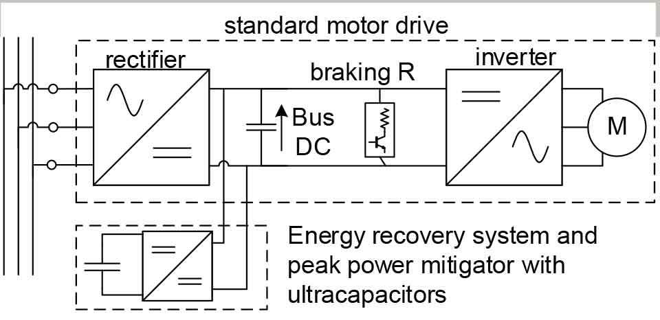
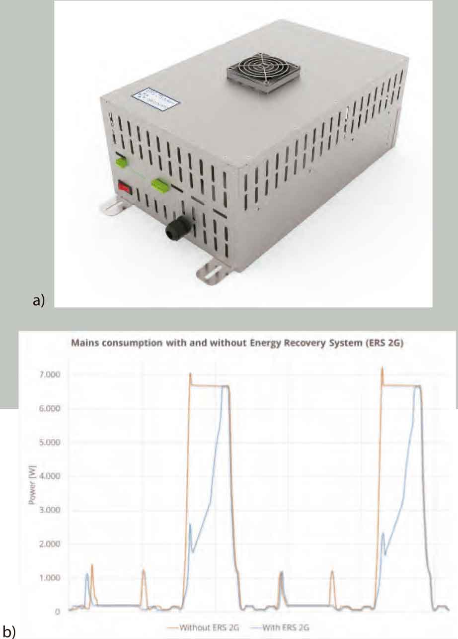
Elevators with gearless traction systems, high traffic and good levels of mechanical efficiency (around 80%) regenerate a considerable amount of energy that is currently either lost at the braking resistor or transferred back to the grid. Thanks to ultracapacitor-based energy storage systems (Figure 3), it is possible to store this energy during braking phases and reuse it during demanding traction phases.
Figure 4-a shows a commercially available[1] solution for such an ERS system. Figure 4-b depicts real measurements of instantaneous power consumption with and without the system. The area between is the energy saved in one trip. The ultracapacitor module is embedded in the system with only two wires connected to any new or existing variable-voltage, variable- frequency (VVVF) drive. Overall savings of up to 62% have been reported in real installations.
The previously listed applications require different energy and power ratings, but their storage voltage levels and some components are common.
Electrical Energy Storage Technologies
Among the possible electrical energy accumulating systems, there are only two technologies that offer mature and commercial products: batteries and ultracapacitors. Both have been manufactured in large-scale quantities for some years, and, therefore, their performance, cost and reliability are optimized and standardized. Batteries are electrochemical devices that operate through chemical reactions. Thus, it becomes difficult to get accurate knowledge of their internal state of operation. A battery is a complex device, the behavior of which is mainly characterized by empirical models. Its charging process is different from its discharging process, and it is difficult to identify its state of charge (SoC) and SoH. Moreover, its aging process depends on the depth of charging/discharging cycles, current, temperature and other parameters.
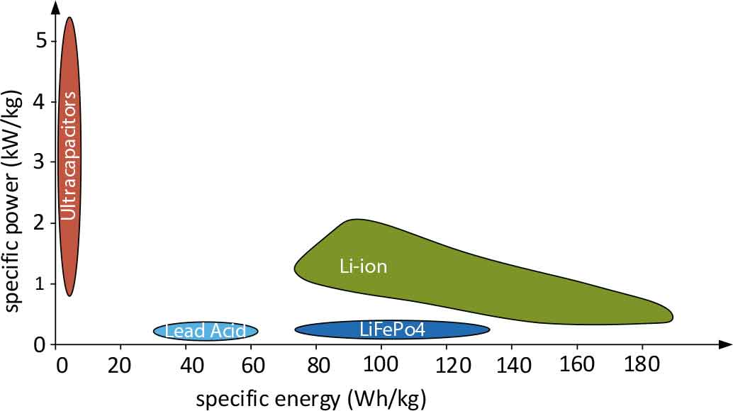
There are currently two main battery technologies in the market: lead-acid and lithium-ion batteries. In the past few years, a special type of lithium battery, the lithium iron phosphate (LiFePO4) battery, has been introduced. It has interesting features of lithium-ion batteries and a brilliant future ahead to completely substitute lead-acid batteries. Figure 5 shows the main power/ energy characteristics of these technologies, and Table 1 summarizes the main features. Data of Table 1 are approximate and have been included only for comparative purposes. It is straightforward to identify lithium-ion as the best choice in terms of functional features: it offers the best specific energy and power figures and the longest lifespan. However, it requires the inclusion of battery management systems (BMSes), and its cost is three to five times higher than the cost of lead-acid technology.
Considering the cost, ease of use and habit gained from many years of successful installations, lead-acid technology is the preferred choice for nonportable energy storage devices.
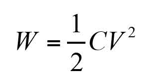
Contrary to batteries, ultracapacitor technology is based on pure capacitive phenomena. Thus, an ultracapacitor-based storage unit admits high charging and discharging powers. Its state of charge is straightforwardly determined by the well-known Equation 1, and it withstands up to one million charging/ discharging cycles (Figure 5 and Table 1). The main drawbacks are its low energy density and its very low nominal voltage (around 2.7 V), which leads to the serialization of many cells and the inclusion of a voltage management system (VMS).
It can be concluded that for UPS functionality, a big amount of energy is required, meaning lead-acid batteries must be installed. But, in the future, with costs of lithium tumbling, the scenario will probably change. Ultracapacitors will be the choice for ERS applications due many cycles and, therefore, benefits a total lack of maintenance and replacements. Hybrid technologies are possible with additional electronics needed to make them truly compatible.
Integration of a 48-V Source in Elevator Traction Systems
The “standard motor drive” block depicted in Figures 1-3 represents the common topology used in elevator drives. When a given electrical power must be exchanged, a current/voltage pair must be selected:
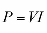
Considering that the current is responsible for most power losses, a high-voltage/low-current set of parameters is preferred. Thus, industry has been adopting standard voltage levels related to the power to be exchanged. When dealing with powers from some kilowatts up to several tens of kilowatts, three-phase 400-V RMS is the electric distribution standard.
Electrical elevator traction systems are modified versions of well-known industrial drivers, which are fed from a 400-V RMS three-phase grid. After being rectified, a 500-600-VDC bus is obtained. This standard drive technology has been used for more than 30 years in industry, so it is extremely robust; reliable; and, due to the large manufacturing scale, cost effective.
The problem arises when a 48-V or an even lower-voltage energy source is feeding part or the entire energy requirements of an elevator. There are two possible scenarios. The first approach is simply to redesign the entire traction system and build a 48-VDC- compatible drive. The second option consists of trying to keep the already developed and well-known elevator drives by interfacing the 48-V energy source and the 600-V bus by a DC/DC power converter. An explanation of these two scenarios follows.
Redesign of the Entire Traction System at 48V
In applications where the three-phase 400-V RMS line is not connected (Figure 2), there is no need to keep high-voltage DC bus levels, so it is possible to build the entire traction system considering a 48-VDC bus (Figure 6). This DC bus voltage limits the available line voltage at the inverter output to 34-V RMS, and the current is multiplied by a factor of 10 or more. So, a new motor and inverter must be carefully designed and installed.
The new voltage level leads to high currents, and, therefore, to avoid high power losses and bulky wires, the storage device, driver and motor must be located close to each other, which sometimes becomes difficult. The main drawback of this approach is that the seller and/or installer must offer and master two different traction systems for the same range of elevators. This is the approach followed by Otis in its Gen2® Switch.[2]
Feature Lead-Acid Lithium-Ion LiFePO4 Ultracapacitor Number of cycles 300-2,000 > 5,000 2,000-7,000 > 1,000,000 Specific power (W/kg) 30-180 300-,2000 15-200 5,000 Specific energy (Wh/kg) 30-60 150-180 90-120 5 BMS/VMS No Yes (BMS) Yes (BMS) Yes (VMS) Cost (€/kWh) 80 200 250 17,000
Integration of a 48-V Source in a Standard Elevator Traction System
Integration of a 48-V source in a standard elevator traction system is the case of Figures 1-b, 2-a, 2-b and 3, where a DC/DC converter is in charge of the energy exchange from the low-voltage storage system to the high-voltage DC bus. First, it is important to point out that neither the low-voltage level (not the high-voltage side) operates at constant voltage. Batteries or ultracapacitors can be installed in the low-voltage side. If a 48-V battery module is considered, its voltage can evolve from 42 to 53 V, depending on the SoC. If ultracapacitors are considered, the situation is even more variable: its voltage can evolve from 24 to 48 V, also depending on the SoC.
The situation is not better on the high-voltage side. If the drive is motoring, energy is removed from the DC bus, which decreases its voltage. In the same way, if the drive is regenerating, energy is delivered to the DC bus, and its voltage increases. The lower voltage limit is determined by the dynamics of the DC/DC converter (i.e., the time it requires until a satisfactory voltage regulation is achieved), whereas the higher voltage limit depends on the same regulation dynamics (if a bidirectional DC/DC converter is used) but also on the voltage value at which the braking resistor switches on. Most commercially available drive manufacturers establish a non-error voltage range from low 400 V to 700 or 800 V.
A cost-effective solution is possible by a large manufacturing scale, so it is desirable to get a DC/DC converter that can operate with a broad range or almost all existing commercial drives. For doing so, it must include plug-and-play functionality allowing the system to operate without producing any disturbance in its regular operation and without any need for modifications in the existing equipment. Thus, if a low-voltage energy source must be integrated on a standard elevator traction system, a DC/DC converter with these features is required:[12]
- Rated power: 4-15 kW (depending on the elevator): DC converters are very easy to parallelize for higher powers.
- Input voltage: 42-53 V or 24-48 V
- Output voltage: 400-800 V, which implies a large input-to- output voltage relation: this ratio is larger than 10 and could be, in some cases, above 20. This ratio makes it difficult to achieve high efficiencies.
- Variable input and output voltage: When the input and output voltages are kept constant, it becomes quite simple to design an optimized high-efficiency converter. But, it is difficult to get high efficiency values along all the operating conditions if input and/or output voltages evolve significantly. Moreover, the highly variable design conditions make it difficult to achieve the design goals.
- High dynamic response: In cases where the elevator is fed exclusively through the DC/DC converter (topologies of Figures 1-b and 2), the same converter is the sole responsible agent keeping the DC bus voltage level within acceptable values. This DC bus is randomly perturbed by input/output powers permanently exchanged with the motor inverter. Therefore, it is crucial to achieve very fast control dynamics capable of rejecting these perturbations.
- Bidirectional energy transfer ability to recover the braking energy in the storage system
- Plug-and-play capability: The control must achieve the above- mentioned dynamics without any complicated link with existing drivers. Only power wires must be connected, and the device must operate in an (almost) autonomous way with any commercial VVVF drive.
- High efficiency (> 90%) along all voltage ranges
- Addition of solar panels (possibly during modernization or later)
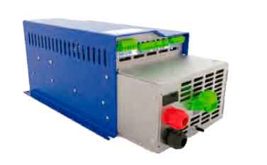
So far, there is only one set of commercially available DC/DC converters compatible with these features.[1] An example can be seen in Figure 7.
It is possible to conclude that the inclusion of a DC/DC power converter makes it possible to get any of the required functionality exploiting well-known standard drives, simplifying the portfolio of the sellers/installers and providing high flexibility. It must be pointed out that a DC/DC power converter limits the power exchange ability, but not the usable energy amount, which depends only on the installed batteries or ultracapacitors.
Conclusions
Energy-intelligent elevators require energy storage. After this, storage requirements are classified in two groups: long-term, high-energy UPS-type functionalities and short-term, low-energy ERS-type functionalities. Among the available accumulation technologies, lead-acid batteries are the preferred choice if a big amount of energy is required, whereas ultracapacitors offer the best performance for high-power, low-energy applications with intensive cyclical operation. Due to commercial availability, cost and design requirements, these are all low-voltage technologies, which can be scaled depending on the total energy requirements.
This scalable system needs to be complemented by a high-gain DC/DC converter with particular features, which has become the main challenge of the proposed architectures. Some power electronic manufacturers have come to understand the need and potential market for such a special converter and, therefore, they have included it as standard product in their portfolio. Thus, using the proposed flexible architecture, any small or medium-sized elevator manufacturer can offer high-end solutions with minor investments, meeting market requirements for higher efficiency and renewable sources of energy quickly.
References
[1] Epic Power Converters S.L. (Epic Power). “Energy Recovery Systems and Intelligent Power Supplies for Drives and Lifts,” epicpower.es (Nov. 2018).
[2] Otis. “Otis Gen2 Switch,” www.otisworldwide.com/site/lb/pages/Gen2-Switch.aspx (Nov. 2018).
[3] Schindler. “Schindler 3300 Solar,” www.schindler.com/content/dk/ internet/da/mobile-loesninger/produkter/elevatorer/ schindler-33001/_jcr_content/iTopPar/downloadlist_5530/
downloadList/54_1433939153593.download.asset.54_1433939153593/ CPH.3300_solar.ENG.pdf (2018).
[4] Power Systems International. “Power Systems for Emergency Evacuation Elevators,” www.powersystemsinternational.com/lift-power-systems/ evacuation-lift-power-systems (Nov. 2018).
[5] Ziehl-Abegg. “EVAC Evacuation Unit,” www.ziehl-abegg.com/gb/en/ product-range/drive-technology/control-technology/evac-evacuation- unit (Nov. 2018).
[6] S. Luri, I. Etxeberria-Otadui, A. Rujas, E. Bilbao, A. González. “Design of a Supercapacitor Based Storage System for Improved Elevator Applications,” 2010 IEEE Energy Conversion Congress and Exposition (ECCE), 4534-4539 (2010).
[7] E. Bilbao, P. Barrade, I. Etxeberria-Otadui, A. Rufer, S. Luri, I. Gil. “Optimal Energy Management Strategy of an Improved Elevator With Energy
Storage Capacity Based on Dynamic Programming,” IEEE Transactions on Industry Applications, Vol. 50, No. 2, 1233 – 1244 (2014).
[8] E. Oyarbide, I. Elizondo, A. Martínez-Iturbe, A. Bernal, J. Irisarri. “Ultracapacitor-Based Plug & Play Energy-Recovery System for Elevator Retrofit,” 2011 IEEE International Symposium on Industrial Electronics (ISIE), 462-467 (2011).
[9] P. Barrade, A. Rufer. “A Supercapacitor-Based Energy Storage System for Elevators With Soft Commutated Interface,” IEEE Transactions on Industry Applications, Vol. 38, No. 5, 1151-1159 (2002).
[10] N. Jabbour, C. Mademlis and I. Kioskeridis. “Improved Performance in a Supercapacitor-Based Energy Storage Control System With Bidirectional DC-DC Converter for Elevator Motor Drives,” 7th IET International Conference on Power Electronics, Machines and Drives (PEMD 2014), Manchester pp. 1-6 (2014).
[11] E. Oyarbide, L.A. Jiménez, P. Molina, R. Gálvez, C. Bernal. “Challenges of Low-Voltage Energy Storage for Lifts,” 5th Symposium on Lift and Escalator Technologies 2015, Northampton, U.K., 2015.
[12] V. Pacheco, P. Molina, L.A. Jimenez, E. Oyarbide. “Improving the Energy Efficiency of Lifts,” 5th Symposium on Lift and Escalator Technologies” Northampton, U.K. (2015).
[13] Oyarbide, E., Bernal, C. Molina, P. Jiménez, L.A., Gálvez, R., Martínez, A. “Voltage Equalization of an Ultracapacitor Module by Cell Grouping Using Number Partitioning Algorithm,” Journal of Power Sources, Elsevier (2016).
Get more of Elevator World. Sign up for our free e-newsletter.
