Machine Room-Less (MRL) Elevators
Aug 2, 2022
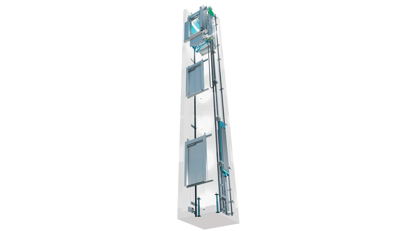
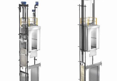
Since the needs increase continuously despite the scarcity of resources, the need for more productive designs with less material have also increases. One of the conveniences emerged showed up in 1996. Until 1996, vertical transportation (VT) designs used to require a special room for the components of the drive and control system. The first elevator that does not require a separate room (machine room) for the system components was introduced to the market in the Netherlands by KONE, in 1996.(1) In short, the design called MRL (machine room-less) system is a radical innovation that shapes today’s technology in the elevator sector.
The most important factor for the birth of MRL system is the invention of gearless elevator motors, which requires less energy than gear drive and offers more efficient in smaller areas. By this means, the smaller engine and other equipment are positioned inside the elevator shaft, meaning a need for a separate room becoming eliminated.
The first target market for the MRL elevators was the low-rise buildings which required VT systems. Using hydraulic lifts in the existing and new low-rise buildings, which do not have a separate place for a machine room over the shaft, was an obligatory choice. However, the sector preferred MRL systems with the introduction of MRL elevators which, are less costly and more environmentally friendly.
Since machine room is not required anymore, the architects had the chance to offer flexible solutions, especially for the design of the spaces over the shaft. MRL systems offer extra advantages in the buildings where panoramic elevators are preferred, as a separate room would deteriorate the appearance. They also provide savings in material, labor and energy costs for the building owners. Therefore, machine room-less systems are the most preferred elevator systems today.
To summarize the advantages and disadvantages of MRL systems:
Advantages
- Since there is no need for a machine room, these spaces can be used for other purposes.
- Saving of material, labor and energy are due to the decrease in construction.
- More environmentally friendly, due to its low energy consumption compared to gear drives, that has machine room and since it uses no oil.
- When compared with the hydraulic lifts, main advantages of MRL systems are:
- Low material and installation cost;
- Low energy consumption;
- Greener, as it does not contain hydraulic oil;
- Better ride quality and comfort;
- Higher speeds;
- Quieter operation;
- Low maintenance and service costs.
Disadvantages
- Maintenance, service and rescue operations are more difficult, compared to systems that have machine room;
- Sound insulation is worse;
- Not always efficient for high-rise, high-speed and high-capacity elevators;
- Riskier for the buildings in seismic zones;
- The motor and the equipment are needed;
- Operating temperature may increase, especially in panoramic glass elevator shafts, as the heat from the engine and the equipment is trapped inside the shaft.
Although there were some definitional deficiencies in the standards and regulations in the years that MRL elevators were introduced to the market, necessary changes have been made.
For example, while there were no rules for MRL systems in EN 81-1:1998(2), rules were defined clearly with the amendments and updates.
Rules for operation, test, maintenance and rescue are defined clearly in the current EN 81-20 standard (Safety rules for the construction and installation of lifts – Lifts for the transport of persons and goods – Part 20: Passenger and goods passenger lifts).
In Conclusion;
MRL designs, which bring freedom in architecture, low energy consumption and greener and economical construction solutions, have developed continuously in the last 20 years and have been the most preferred elevator systems. MRL systems, which rapidly develop rapidly, meet the functional elevator needs in high-rise buildings and carry the potential to remove machine room systems within the near future.
| EN 81-1:1998 | EN 81-1:1998/A2:2004 (3) |
| 3. DEFINITIONS Pulley room: (local des poulies) (Rollenraum): A room not containing the machine, but where the pulleys, the overspeed governor and the electrical equipment can also be housed. Machine room: (local des machines) (Triebwerksraum): A room in which machine or machines and/or the associated equipment are placed. | 3. DEFINITIONS: Pulley space: (Emplacement de poulies) (Aufstellungsort von Seilrollen): space(s) inside or outside of the well where pulleys are placed. Machinery space: (Emplacement de machinerie) (Aufstellungsort von Triebwerk und Steuerung): space(s) inside or outside of the well where the machinery as a whole or in parts is placed. |
| 6- MACHINE AND PULLEY ROOMS 6.1- GENERAL PROVISIONS: 6.1.1- Lift machines, their associated equipment and pulleys shall be in a special room, comprising solid walls, ceiling, floor and door and/or trap, and shall be accessible only to authorized persons (maintenance, inspection and rescue). Machine or pulley rooms shall not be used for purposes other than lifts. They shall not contain ducts, cables or devices other than for the lift. | 6 -MACHINE AND PULLEY ROOMS 6.1 GENERAL PROVISIONS: Machinery and pulleys shall be located in machinery and pulley spaces. These spaces and the associated working areas shall be accessible. Provisions shall be made to allow access to the spaces only to authorized persons (maintenance, inspection and rescue). The spaces and the associated working areas shall be suitably protected against environmental influences to be taken into consideration and provisions made for suitable areas for maintenance/inspection work and emergency operation. (See 0.2.2, 0.2.5 and 0.3.3.) |
| 12.5 EMERGENCY OPERATION 12.5.2 If the effort defined in 12.5.1is greater than 400 N, a means of emergency electrical operation from the machine room shall be provided in accordance with 14.2.1.4. | 12.5 EMERGENCY OPERATION 12.5.2 If the effort defined in 12.5.1 is greater than 400 N, a means of emergency electrical operation shall be provided in accordance with 14.2.1.4. This means shall be located in the relevant machinery space: – Machine room (6.3), – Machinery cabinet (6.5.2), or – On the emergency and test panel(s) (6.6). |
| 13.4- MAIN SWITCHES 13.4.1– Machine rooms shall contain, for each lift, a main switch capable of breaking the supply to the lift on all the live conductors… 13.4.2– The main switches as defined in 13.4.1 shall have stable open and closed positions, and shall be capable of being locked-off in the open position, with the use of a padlock or equivalent, to ensure no inadvertent operation. The control mechanism for the main switch shall be easily and rapidly accessible from the entrance(s) to the machine room. If the machine room is common to several lifts, the control mechanism of the main switches shall allow the lift concerned to be identified easily. | 13.4 MAIN SWITCHES 13.4.1 For each lift, a main switch capable of breaking the supply to the lift on all the live conductors shall be provided. This switch shall be capable of interrupting the highest current involved in normal conditions of use of the lift… 13.4.1.2 This switch shall be located: a) in the machine room where it exists; b) where no machine room exists, in the control cabinet, except if this cabinet is mounted in the well, or c) at the emergency and tests panel(s) (6.6) when the control cabinet is mounted in the well. If the emergency panel is separate from the test panel, the switch shall be at the emergency panel (6.6). If the main switch is not easily accessible from the control cabinet, then the cabinet shall be provided with an isolating switch as required in 13.4.2. |
References
2) EN 81-1:1998 Safety rules for the construction and installation of lifts – Part 1: Electric lifts (TS 10922 EN 81-1 ASANSÖRLER – YAPIM VE MONTAJ İÇİN GÜVENLİK KURALLARI – BÖLÜM 1: ELEKTRİKLİ ASANSÖRLER-NİSAN2001)
3) EN 81-1:1998/A2 (2004) Safety rules for the construction and installation of lifts – Part 1: Electric lifts A2: Machinery and pulley spaces (TS 10922 EN 81-1/A2 Asansörler- Yapım ve montaj için güvenlik kuralları- bölüm 1: Elektrikli asansörler – A2: Makina ve makara boşlukları – 27.12.2005)
Get more of Elevator World. Sign up for our free e-newsletter.

