
Reliability centered maintenance of elevators – an introduction
by Lakshmanan Raja

Value: 1 contact hour (0.1 CEU)
This article is approved for Continuing Education by NAEC for CET® and CAT®.
EW Continuing Education is currently approved in the following states: AL, AR CO, FL, GA, IL, IN, KY, MD, MO, MS, MT, NJ, OK, PA, UT, VA, VT, WA, WI and WV | Canadian Province of BC & ON. Please check for specific course verification of approval at www.elevatorbooks.com.
Learning Objectives
After reading this article, you should have learned about:
- Understanding the component properties like load, strength distribution, factor of safety, overload and fatigue
- Comparing the various failure patterns and relating the failure propagation using the P-F curve
- Analyzing the different maintenance tasks such as time directed, condition directed and run-to-fail, failure-finding tasks and its relevant application to elevator components maintenance
- Reliability centered maintenance, its purpose and processes in the elevator industry
- Applying the knowledge gained by selecting the right maintenance strategy based on the potential failure symptoms/failure mode of the components in elevators
Introduction
The main objective of elevator maintenance is to keep elevators in an acceptable condition so that they will perform their intended function fully without any compromise. Unfortunately, elevator maintenance is not always taken as seriously as it should be, and units fail. Then, the resources needed are committed to repair or replace the failed equipment. This was acceptable in earlier days, when the buildings were not as tall, and downtime did not matter as much. At the same time, most elevator systems were simple, and components were over designed. As a result, there was no need for systematic maintenance beyond simple cleaning, servicing and lubrication routines. As building heights grew, downtime became a priority. This led to the concept of preventive maintenance. Therefore, a maintenance strategy based on inspection, component replacement and overhauling at fixed intervals — regardless of condition — is now in practice. Currently, the industry is devoting a great deal of attention to performing planned maintenance tasks correctly without ensuring that the planned tasks are the required tasks. So, is this way of doing maintenance effective? How can it be improved further to suit the modern elevator system, which is a functional-based model with the combination of mechanical, electrical, electronic and software engineering? We will investigate how to improve maintenance in this article. First and foremost, for planning maintenance in an effective way, we need to understand how components fail.
Understanding Failure
No physical items have a zero-failure rate. The load placed on machine parts from use stresses their physical structure. If the stress is high, the bond across the load-carrying section separates and the material breaks: This is overload. If the loading is repetitive, only a few bonds separate and the remaining unbroken bonds carry the load with less structural strength available: This is fatigue. Material strength and machine loading are ideally envisioned to be deterministic, but in the practical world, they are probabilistic in nature. This is not only applicable to mechanical components, but electronic devices as well. The loading on the electronic devices may be the current it carries or the number of switching the transistor makes. The effect is the same, and the designed capacity is not going to be deterministic for the same type of components.
The following figures show the probability density function curve of load and strength. They show the natural spread of variation in stress and carrying capacity of identically specified material bought from different suppliers.
Figure 1 shows the set of curves where the equipment is operated and maintained in the designer-intended way. The strength distribution of the material used and the range of expected operational stresses are wide apart. The designed safety margin/factor of safety is the function of this gap.
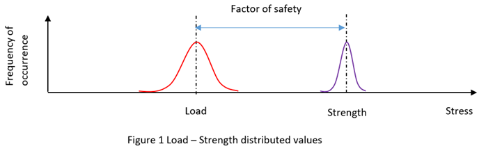
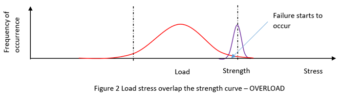
Figure 2 shows the overload situation in which the distribution of operational stresses overlaps the strength curve.
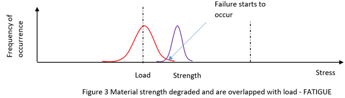
When a material is subjected to repeated stresses, it fails at a stress level below the yield point stress. This type of material failure is known as fatigue. Figure 3 shows the situation, where the material properties are degraded because of fatigue until the material is too weak to carry the rated load, and failure starts to occur.
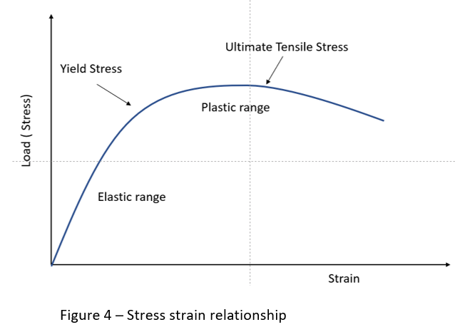
When the load increases, more deformation is caused. This relationship in metal is known as Hooke’s Law, shown in Figure 4. In the elastic region, load and strain are proportional and the metal acts like a spring. If the load increases, the strain rises to the point that the microstructure cannot sustain the load, and it enters the plastic range where the failure occurs. Material overstress happens in electrical, electronic and mechanical parts that undergo excessive operational loading and environmental stress from vibration, temperature fluctuation, etc. Overstressed parts are damaged, and the failure starts to initiate.
Failure Patterns
A traditional view of optimizing equipment availability is by doing some overhauls or component replacement at fixed intervals. The classical thinking of such a failure pattern is shown in Figure 5.
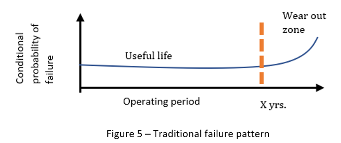
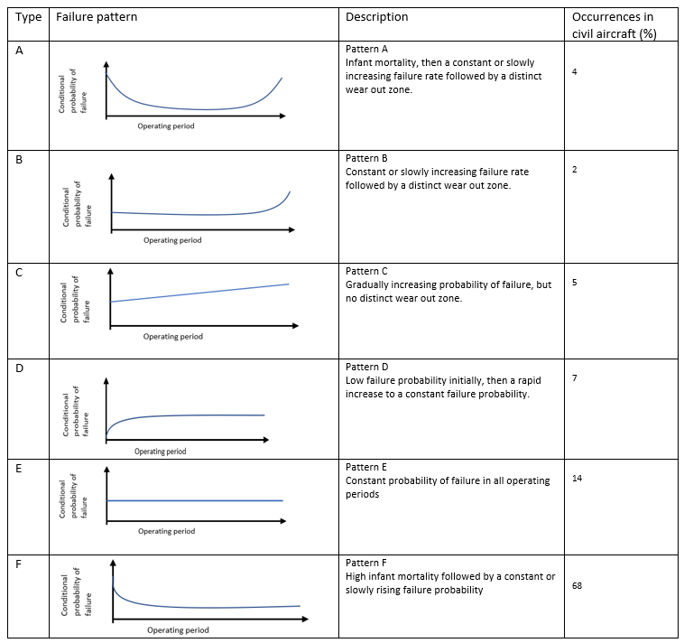
We can understand from the pattern: It was assumed that there is an obvious wear-out zone after the equipment is used for X number of years. However, newer systems are more complex than they were 20 years ago. This has led to changes in the pattern of failure, and there are six dominant failure patterns identified in the study done on the civil aircraft industry, which is shown in Table 1. The important point to note here is, the failure patterns A, B and C are age-related, whereas D, E and F are not age-related. The percentage of occurrence shows that failure patterns D, E and F contribute to more than 89% of the failure analyzed, which don’t have any definite wear-out zone. It means that overhauls and replacements conducted at specific intervals, which is current practice, may not be effective. In addition, it may create infant mortality because of the non-required intrusive maintenance activities. Customer feedback such as, “The elevator was running quite well, but after the elevator personnel did the service, it started to break down often,” is a good example of the abovementioned situation.
Detection of Failures
From the above discussion, we understand that many failure modes lack a definitive wear-out zone. However, most failures will give some sort of warning about the upcoming failure. The final stages of failure propagations are explained in Figure 6, which is called the P-F curve. The point at which the degradation detected is at point P. After this, failure will eventually happen. How soon will depend on the stress imposed on the failing part. Functional failure occurs at point F. The time interval between points P and F is called the P-F interval, which is also called lead-time to failure. This is the interval in which the potential failure becomes detectable and the point at which it degrades into a functional failure.
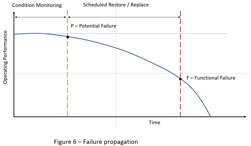
To catch the potential failures and correct them on time, the interval between the preventive maintenance task should be less than the P-F interval.
If the potential failure is detected at an early stage, we get a longer P-F interval. The longer P-F interval means that the inspection interval can be longer, and the maintenance crew will have more time to take the needed action to avoid the consequences of failure. But the challenge here is, for detecting the potential failure (point P) early, smaller deviation from the normal condition is required to be detected. This will be difficult, especially when the final stages of deteriorations are not linear.
Detection techniques using human senses are very common and cheap. Such techniques are common in the elevator and escalator industry. The main advantage of such detection with human senses is they can detect a very wide range of potential failure conditions using the four senses, as shown in Figure 7.
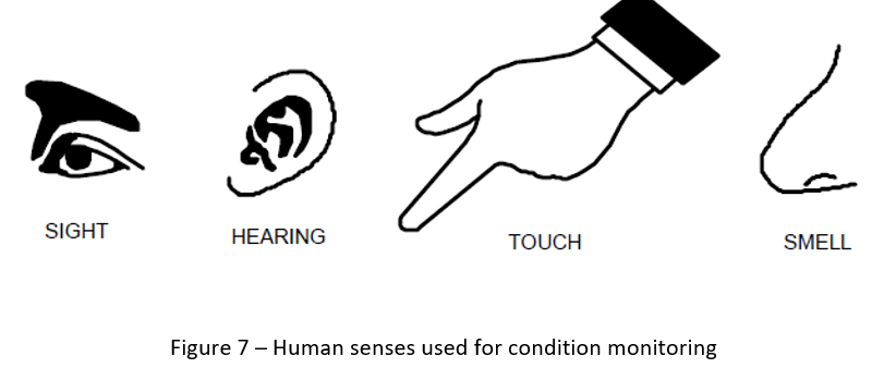
However, our human senses may not be sensitive or precise enough to detect such smaller deviation consistently, and this will result in a very short P-F interval. When we rely on technology by using suitable instruments to monitor and detect the condition of equipment, it is called condition monitoring. Such condition monitoring instruments, if properly calibrated, will detect the potential failure symptoms early, which will result in a longer P-F interval than human senses. Most of the mechanical components, like suspension ropes, driving sheaves, mechanical linkages in the car door, rollers, etc., will go through the recognizable stages of degradation. But electronic components (PCBs with solid-state devices) will not show any visible signs of potential failure. Recognizing their degradation with human senses is very challenging.
Systematic Failure
The failures seen so far involve physical items, which are random in nature and a result of one or more possible degradation mechanisms in the hardware. However, there are failures, related in a deterministic way to a certain cause that can be eliminated only by a modification of the design or of the manufacturing process, operational procedures, documentation or other relevant factors. These types of failures are called systematic failures. Example: Adjustment and maintenance procedure gives wrong information on a traction machine brake spring setting. There are also failures caused by human error, which may be sometimes classified as random or deterministic in nature, depending on the nature of error.
So, different maintenance approaches should be adopted to address all of these types of failures in the modern system.
Maintenance Tasks
We can group the maintenance tasks broadly into three types — preventive, failure finding and corrective — which is shown in Figure 8.
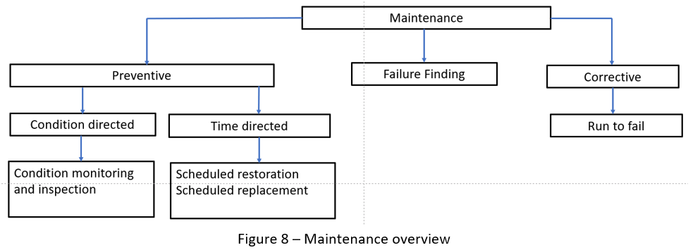
Preventive maintenance is undertaken prior to failure. This can be condition directed, which can be achieved by monitoring the condition until failure is imminent, or by a predetermined (time directed) on a fixed interval (such as calendar time, operating hours, number of cycles) consisting of scheduled restoration or replacement of an item or its components.
Failure finding cannot be treated as a preventive maintenance task since it is only a functional test to detect the health of the hidden function of the system. Example: a periodical test conducted to verify the function of speed governor and safety gear.
If the outcome of the failure-finding task shows some form of functional degradation, then possible preventive maintenance can be carried out. If the failure-finding task outcome shows a complete functional failure, then a corrective maintenance task must be carried out.
Corrective maintenance restores the functions of an item after failure has occurred or performance fails to meet stated limits. Some failures are acceptable if the consequences of failure are tolerable compared to the cost of preventive maintenance and the subsequent loss due to failure. This results in a planned run-to-failure approach to maintenance. Examples: call button, floor indicator failures or in-car light/fan failures.
Preventive maintenance is normally scheduled or based on a predetermined set of conditions, while corrective maintenance is unscheduled. There is a new way of maintenance called reliability centered maintenance (RCM) that is getting attention now. RCM identifies the optimal preventive and corrective maintenance tasks (approach) and depends on the failure mode, which we will see in the subsequent sections.
RCM of Elevators
The traditional thinking of performing preventive maintenance to preserve equipment results in many problems. The most important among them are:
- It treats all failures equally without considering the usage and the environment of the elevator and performs maintenance simply because there is an opportunity to do so, which wastes resources.
- By executing such maintenance, activity on the non-deteriorated parts could cause damage due to intrusive action, thereby increasing the chances of human error.
The purpose of the RCM is not to preserve the equipment for the sake of the equipment, but rather to preserve its functions. In the process of RCM, you have to identify the importance of each function and select the effective maintenance task to detect and mitigate the identified functional failures. Rigorous RCM analysis has been used in aircraft, space, defense and nuclear industries where functional failure has the potential to result in large losses of life or an extreme environmental impact.
Basically, the RCM process answers the following seven essential questions:
- What are the functions and associated desired standards of performance of the asset in its present operating context?
- In what ways can the asset fail to fulfill its functions (functional failures)?
- What causes each functional failure (failure modes)?
- What happens when each failure occurs (failure effects)?
- In what way does each failure matter (failure consequences)?
- What should be done to predict or prevent each failure (maintenance task)?
- What should be done if a suitable proactive task cannot be found (default actions)?
For question 1, the expected performance standard can be obtained from the relevant codes like EN 81 or ASME A17, etc. The operating context depends on the environment where the elevator is installed.
For questions 2 to 5, Failure Mode Effect Analysis (FMEA) will be a relevant tool to get that information. FMEA is similar to Root Cause Analysis but is done before the failure happens to avoid the failures. However, FMEA was primarily designed to assess risk, whereas RCM uses a structured decision process to determine a task to detect, eliminate or reduce the frequency of occurrence/consequence of each specific failure mode by selecting the appropriate maintenance task, which is addressed by question 6 and 7. RCM uses an optimum mix of maintenance tasks like time directed (TD), condition directed (CD), failure finding (FF) and run-to-fail (RTF) based on the nature of the failure mode.
Table 2 provides more information on the tasks and some examples of their relevant applications for elevators.
| Maintenance Task Types | Description |
| Condition Directed (CD) | Suitable for most of the failure patterns, where the potential failure symptoms are easily detectable before the functional failure occurs, provided it is economically justifiable. Example: Failure modes in mechanical components like door operator, traction machine parts as gear, sheave, coupling bushes and ropes. |
| Time Directed (TD) Scheduled Restoration / Scheduled Discard | Suitable for age-related failure mode where the useful life is well known. Also used in some cases where the potential failure symptoms are not easily detectable before the functional failure occurs and the impact of the failure is high. However, this should be economically justifiable. Example: Replacement of VFD after their useful life. Yearly overhauling of traction machine brake. |
| Failure Finding (FF) | A scheduled task that seeks to determine if a hidden failure has occurred or is about to occur. Example: category tests, routine annual inspections on testing safety gear, unintended car movement prevention and ascending car overspeed prevention. |
| Run-To-Fail (RTF) | Task/replacement of component is done only after the failure occurs. Suitable for where the cost and impact of failure is less than the cost of early replacement based on TD. Example: In-car light bulb, call button lights and floor indicators etc. |
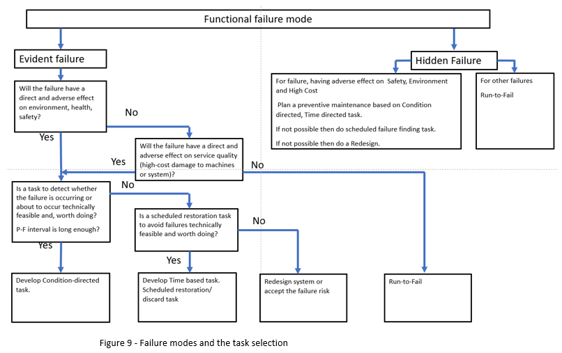
As mentioned earlier, the maintenance task needs to be focused on the prevention of failure mode. For example, your author had tabulated the failure modes of an electromechanical brake system with the recommended maintenance task in Table 3. You might have noticed that certain failure modes require competency development by training, and some require a design review or changes, which are the examples of systematic failures. Figure 9 gives general guidance on maintenance task selection for a given failure mode. The maintenance task selected should be technically feasible and worth doing.
The analysis in Table 3 guides us in selecting the appropriate maintenance task for different failure modes. Selecting the task interval is the next challenge. For the CD task, the interval on the condition monitoring should be less than the P-F interval. A task interval equal to half of the P-F interval is typically used since it provides two chances for the degradation to be detected. When a greater level of accuracy is desired, a smaller task interval is selected, but it should be justifiable by cost.
Elevator System |
|||
Function
|
|||
Functional Failure |
Failure Mode (causes of failures) |
Failure Effect (consequences of failure) |
Recommended Task |
Not opening |
Solenoid open circuited |
Motor current exceeds the limit, and the overcurrent trip will be activated |
RTF/ TD – Scheduled discard |
Solenoid short circuited |
Brake current exceeds the limit, and the over current rip will be activated |
RTF/ TD -Scheduled discard |
|
Mechanical components jammed in closed condition |
Motor current exceeds the limit, and the overcurrent trip will be activated |
CD / TD Scheduled restoration |
|
Spring force set at very high |
Motor current exceeds the limit, and the overcurrent trip will be activated |
Competency issue – Training |
|
Open partially when the current is supplied to the coil |
Mechanical components movement is affected by friction |
Brake pad worn off or Motor current exceeds the limit and trip the over current protection. |
CD / TD- Scheduled restoration |
Spring force set at moderately high |
Brake pad worn off or Motor current exceeds the limit and trip the over current protection. |
Competency issue – Training |
|
Unable to stop the car with 125% rated load |
One brake pad worn off |
The other set of brake should be able to stop the car |
CD |
Two brake pads worn off |
The elevator car will go through uncontrolled motion until it is stopped by some other mechanical means |
CD |
|
Brake coil got energised permanently due to control circuit problem |
The elevator car will go through uncontrolled motion until it is stopped by some other mechanical means |
Design issue – Design Review |
|
One brake plunger mechanically jammed in open condition |
The other set of brake should be able to stop the car |
CD / TD-Scheduled restoration |
|
Two brake plungers also jammed in open condition |
The elevator car will go through uncontrolled motion until it is stopped by some other mechanical means |
CD / TD-Scheduled restoration |
|
One Brake lever jammed in opened condition |
The other set of brake should be able to stop the car |
CD / TD-Scheduled restoration |
|
Two Brake lever jammed in opened condition |
The elevator car will go through uncontrolled motion until it is stopped by some other speed control means |
CD / TD-Scheduled restoration |
|
Brake drum oily |
The elevator car will go through uncontrolled motion until it is stopped by some other speed control means |
Competency issue – Training |
|
Stopping the car with retardation exceeds the specified limit |
Spring force set at very high |
Sudden stopping and the associated jerk will can cause injury to the passenger. |
Competency issue – Training |
For the schedule restoration or replacement, the interval is based on an evaluation of failure modes, safe life or useful life. Safe life — prescribed service life with a declared probability of catastrophic failure. Useful life — time interval, from first use until user requirements are no longer met, due to economics of operation and maintenance, or obsolescence.
The author has listed many elevator components and suggested maintenance tasks based on the potential failure symptoms of components in Table 4, and it is not comprehensive. Readers may further refine it by doing a failure mode analysis for each component to find a suitable maintenance task based on the failure modes derived. In addition, the identified maintenance tasks will also help in finding the information for the support activities, such as the provisioning of spares, level of repair analysis, requirements for tools and test equipment, manpower skill levels, etc. As every building is different, feedback on the performance of the implemented maintenance task/schedules should be continuously acquired for continuous improvement.
| Subsystems | Components | Potential failure symptoms | Maintenance Task |
1 | Traction and Brake System |
|
|
|
| Motor | Bearing | Vibration / noise | CD |
|
| Winding | Frequent trip due to over current, insulation strength | CD |
|
| Encoder | Intermittent stopping with speed control failure error | TD, CD |
| Gear | Worm gear | Backlash / Worn / Crack | CD |
|
| Gear wheel | Backlash / Worn / Crack | CD |
|
| Bearing | Vibration / noise | CD |
|
| Oil Seals | Minor leak | CD |
|
| Coupling bushes | Noise, free play at coupling link | CD |
| Brake | Brake pad | Reduction in thickness, scratches on brake drum | CD |
|
| Brake coil | No easily detectable symptoms | TD |
|
| Brake plunger | Free movement/ response time | CD |
|
| Brake lever | Free movement/ response time | CD |
|
| Brake spring | Crack, compression limit exceeded | CD |
|
| Brake switches | No easily detectable symptoms | TD |
| Machinery support structures | Beam | Corrosion | CD |
|
| Isolation pad | Compression limit / vibration | CD |
2 | Ropes and Sheaves | |||
|
| Suspension Rope / Compensation ropes | Diameter / worn off signs / rope slip | CD |
|
| Sheave | Worn off sign on groove, rope seating below the groove, excessive rope slip, noisy, wobbling while rotating | CD |
|
| Sheave bearing | Vibration / noise | CD |
|
| Diverting pulleys | Rope seating below the grove level, noisy, wobbling while rotating | CD |
3 | Safety gear and governor system | |||
| Safety gear | Wedges | Deformed, crack | TD |
|
| Safety gear switch | No easily detectable symptoms | TD |
| Governor | Governor assembly | Noisy, wobbling while rotating | CD |
|
| Governor rope | Diameter / worn off signs / rope slip | CD |
|
| Overspeed switches | No detectable symptoms | TD |
|
| Tension pulley | Noisy, wobbling while rotating | CD |
|
| Rope slackening switch | No easily detectable symptoms apart from physical damages | TD |
4 | Buffers | |||
|
| Hydraulic Buffers | Crack, corrosion, oil leak, restoring time long | CD |
|
| Buffer switch | No detectable symptoms | TD |
|
| PU buffer | Crack, disintegrated, life span | CD, TD |
|
| Spring buffer | Crack, corrosion, rusty |
|
5 | Landing door and car door system | |||
| Landing door | Air cord rope | Broken strands | CD |
|
| Hanger roller | Noisy, vibration | CD |
|
| Door track | Noisy, vibration during door operation, deformed | CD |
|
| Upthrust / eccentric roller | Jammed, rusty | CD |
|
| Door switches | No detectable symptoms | TD |
|
| Interlock roller | Damaged, worn off signs, difficult to rotate | CD |
|
| Door shoes | Worn off, noise, vibration | CD |
|
| Air cord rope | Broken strands, noise | CD |
| Car door | Belt | Stretched beyond limit, worn off | CD |
|
| Chain | Stretched beyond limit, worn off | CD |
|
| Door hanger | Noisy, abnormal vibration | CD |
|
| Door track | Worn off, door operation noisy | CD |
|
| Door shoes | Worn off, door operation noisy | CD |
|
| Door switches | No detectable symptoms | TD |
|
| Door encoder | Intermittent door operation failure, error code | CD |
|
| Light curtain | No. of LED fails | CD |
|
| Safety edge switch | Intermittent stopping of the door while closing | TD, CD |
|
| Safety edge cable | Intermittent stopping of the door while closing | TD, CD |
6 | Elevator car and landing | Lights | It’s not cost effective to monitor the symptoms | RTF |
|
| Fan | RTF | |
|
| Push button | RTF | |
|
| Indicators | RTF | |
|
| Leveling switches / sensors | Intermittent mis-leveling, error code | CD |
|
| Car structure | Corrosion, rust | CD |
7 | Hoistway items | |||
|
| Slow down and limit switches | Intermittent error captured in the error log. | CD |
|
| Buffers | Corrosion, rust, restoration time | CD |
|
| Compensation pulley | Bearing noisy, rope seating below the grove level | CD |
|
| Compensation rope / chain | Rusty, worn off | TD, CD |
|
| Guide rails | Corrosion, rust | CD |
|
| Guide brackets | Corrosion, rust | CD |
|
| Guide shoes | Corrosion, vibration | CD |
|
| Guide shoe liner | Worn – free play beyond the limit | TD, CD |
|
| Traveling cable | Intermittent connection loss, visible damages | TD, CD |
8 | Controller |
|
|
|
|
| Inverter | Error code related to speed control failure, over heating symptoms, misleveling | TD, CD |
|
| Controller PCB | Error code, intermittent stopping | TD, CD |
|
| Relays | Error code, higher contact resistance | TD, CD |
|
| Contactor | Error code, higher contact resistance | TD, CD |
Conclusions
There is a saying, “If you always do what you always did, you will always get what you always got.” For any improvement, change in the action is needed. Improving the uptime of the elevators in the building to cope with the modern, fast-paced world is an essential need now. For that, understanding the failure of elevator components is important, and to be more accurate, understanding the components’ failure mode is very important. The maintenance strategy should be decided based on the failure mode of each component. Developments in condition monitoring and remote monitoring will help in getting the required data without making a site visit. However, the collected data/information should be analyzed by skilled personnel for selecting the proper maintenance strategy. I hope this article sheds some light on understanding the failure and maintenance strategy and has given some introduction to RCM. Readers are recommended to refer to the reference section for more information.
References
[1] Moubray, John. Reliability-centred maintenance. Industrial Press Inc., 2001.
[2] Gulati, Ramesh, and Ricky Smith. Maintenance and reliability best practices. Industrial Press Inc., 2009.
[3] BS EN 60300-3-11:2009 — Dependability management. Application guide. Reliability centered maintenance
[4] Sondalini, Mike. “Industrial and manufacturing wellness.” Industrial Press Inc., 2016.
[5] NASA — Reliability Cantered Maintenance Guide for Facilities and Collateral Equipment — 2008
[6] IEC 61508 – 4 Functional safety of electrical/electronic/programmable electronic safety-related systems — Part 4: Definitions and abbreviations
Learning-Reinforcement Questions
Use the below learning-reinforcement questions to study for the Continuing Education Assessment Exam available online at www.elevatorbooks.com or on p. 126 of this issue.
- State the advantages of using instruments to do condition monitoring rather than the human senses.
- What are the challenges and benefits of using only the time-directed preventive maintenance tasks?
- List the components/subsystems in an elevator, where condition-directed maintenance tasks are preferred.
- Explain how the upcoming technology like remote monitoring and data analytics will help in implementing RCM in the elevator industry.
- List the advantages and disadvantages of implementing the RCM in elevator industry.
Also Read: Vertical Sliding Door Maintenance
Get more of Elevator World. Sign up for our free e-newsletter.
![]()


 Holy Alliance?")
![]()