Making Hydraulic Elevators Heat Resilient
Sep 1, 2016
The dangers of heat in hydraulic systems and how to guard against them
One of the biggest technical challenges a hydraulic engineer faces is designing a heat-resilient hydraulic elevator system. Such a challenge becomes even more difficult when the system has to work in an environment with high ambient temperature, a humid climate, poor ventilation and very high usage.
A hydraulic elevator is typically made up of components sourced from different manufacturers. Every component manufacturer, a specialist in its own domain, optimizes the design and performance of its own product. Much of the energy and focus during component design is on tolerances, production techniques, minimizing pressure losses, fulfilling elevator safety norms, quality control and overall functionality of the product.
Learning Objectives
After reading this article, you should have learned about:
♦ Understanding the effects of heat on a hydraulic elevator and the source of heat generation
♦ Effective solutions to make hydraulic elevators heat resilient and other best practices
♦ Laws of thermodynamics, including calculation and analyzing heat load
♦ Selection of coolers (if necessary)
♦ Design optimization
After reading this article, you should have learned about:
It is the job of the system designer to optimize the working of the complete assembly, keeping in mind its application and operating conditions. This involves selecting the right components in compliance with elevator safety code, sizing the components, running heat calculations and analyzing elevator traffic so the complete elevator system can deliver the needed performance. This article describes how to get this process right, focusing on minimizing heat generation.
Effects of Heat on a Hydraulic Elevator
Heat alters the viscosity of the hydraulic fluid, which triggers the problems. Hot (thin) oil results in:
- Increased leakage within the system (pumps, valves etc.), reducing the volumetric efficiency of the system
- Erratic hard start-and-stop travel characteristics, over traveling of the floor level, and increased wear and tear of oil seals and components
- Oxidation of oil accelerates its degradation by changing its properties and reducing its lifespan.
A simple checklist sums up everything that can help deliver a heat-resilient elevator system:
- Source of heat generation
- Ways to minimize heat generation
- Calculating and analyzing heat load
- Optimizing the hydraulic elevator system to naturally dissipate the generated heat
- Sizing coolers if forced convection is necessary
Source of Heat Generation
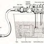
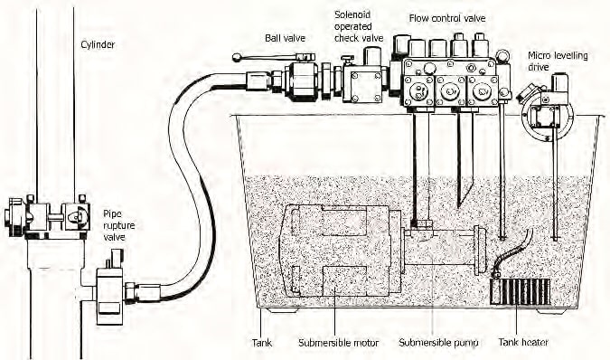
The hydraulic power unit is made up of a tank, oil, motor, pump, control valve and related accessories connected to the hydraulic cylinder with a hose pipe or a metal pipe. This driving unit is usually located in the machine room or, in some machine-room-less (MRL) units, in the elevator shaft itself.
The following practices can contribute to heat generation of the power unit:
- Power unit too small for the elevator it is driving
- Placement within a poorly ventilated or unventilated place, such as too close to a wall
- Very small machine room
- Tank made of (nonmetallic) material that cannot dissipate heat effectively
- Inadequate piping, causing turbulent flow, pressure losses and heat generation
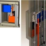
As a general rule, the size (volume) of an oil tank should be at least 2.2 X pump flow, with at least 10 cm of space still left from the tank cover to the oil surface when the elevator is on buffer. The unit should be located in a room with cross-ventilation, which can help the heated air dissipate quickly. If the installation is an MRL type, place the power unit in a wall closet with an opening into the shaft. This helps cool the tank automatically as the car movement in the shaft pushes air on the tank with its movement (Figure 2). Metallic tanks are preferred, as they can dissipate heat much more easily than fiber and plastic tanks. Adequate piping size should be selected, and the usage of reducers, unnecessary bends and adapters should be avoided.
Oil
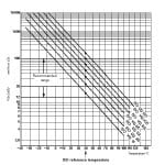
Using the correct oil type can significantly contribute in keeping oil temperature under control. Hydraulic fluid best suited for elevator application is one that has a relatively low change in viscosity when its temperature changes. The temperature and viscosity of hydraulic oil is inversely related: oil viscosity decreases with increase in temperature.
The viscosity index (VI) is a single-number representation of the viscosity temperature characteristics of a fluid. The greater the value of the VI, the smaller the variation in viscosity for a given change in temperature or vice-versa.
Hydraulic lifts consistently used in warm ambient temperatures (above 30°C) and running in heavy traffic should use an ISO VG 68 type of oil. Oversizing the tank for it to contain oil volume three times the pump flow should be used when temperature of the oil during the working cycle of the elevator rises by 25-30°C.
Control Valve
A flow control valve regulates the flow of oil by letting the excess oil flow back to the tank during the bypass, acceleration, deceleration and leveling stages, giving passengers a smoother ride experience. Many different types of flow control valve specifically designed for hydraulic elevators are available. These range from the simplest and most widely used mechanical valves, servo electronic valves with proportional solenoids, to variable-voltage, variable-frequency (VVVF)-driven valves.
A wrongly adjusted control valve can contribute to heating of the oil. Improperly set pressure-relief valve, longer bypass and leveling times can impact the oil temperature on every run. Undersizing the valve, especially at high operating pressure, can also contribute to unnecessary temperature increase. Using the wrong valve type in a heavily used hydraulic elevator, like installations in public places or hospitals, for instance, can contribute to the heating of the system.
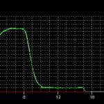
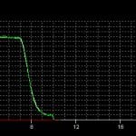
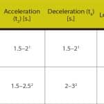
Correct valve adjustments are critical for trouble-free operation and minimizing wear and tear of the components and oil seals. A wrongly adjusted valve during the installation phase not only results in erratic travel characteristics, but also keeps heating the oil for the rest of the time. For example, Figure 4 shows a wrongly adjusted valve with unnecessary longer leveling time; whereas Figure 5 shows the travel with optimum leveling time. Table 1 shows optimum bypass, acceleration, deceleration and leveling timings of valve adjustments.
Undersizing
Using the control valve at or more than the full flow capacity causes high pressure losses and turbulence, which heat the oil quickly. High operating pressure (more than 65 bar) adds to the heating problem. Manufacturers’ recommended operating flow range for the given size should not be ignored in the interest of minimizing pressure losses at maximum flow. Using the next-bigger valve size for pump flow nearing maximum flow range is always recommended to prevent turbulence. While selecting connectors, piping, reducers and bends, the narrowest flow passage should be appropriate for handling the maximum flow without causing turbulence or huge pressure losses.
Valve Type
VVVF valves with inverters are the best option when temperature and pressure compensation are desired with dynamically changing operating conditions beyond the scope of simple mechanical control valves. An inverter-based system not only minimizes heat generation, but also energy consumption by up to 60%.
Calculating and Analyzing Heat Load
The first law of thermodynamics says that energy cannot be created or destroyed, simply transformed from one type to another. Thus, in a hydraulic elevator system, energy must be added to the hydraulic oil to elevate the car to its destination. An energy source such as an electric motor is needed to drive a pump to convert the mechanical energy into flow. Resistance to flow in the hydraulic system creates pressure, the energy of which actuates the cylinder of the elevator system. Hence, the complete hydraulic elevator system is actually an energy-transfer system. As the energy is simultaneously transformed from one type to another, some of the energy in the system is converted into heat and is no longer available for useful work. The lost energy that gets converted into heat increases the temperature of the oil in the tank. The heat in the oil is then naturally dissipated to the environment until the temperature gradient between the oil and ambient temperature equalizes.
Heat dissipates from a hydraulic system mainly in two ways: natural convection and forced convection. Natural convection takes place as heat moves from the various system components to the surrounding air because of the temperature gradient. It is good when natural convection dissipates all the heat generated by the elevator system. If not, system temperature will continue to rise, thereby necessitating a heat exchanger, which is the second heat-dissipation mode (forced convection). A third heat-dissipation mode, radiation, is in action, too, but its effect is essentially negligible.
In principle, the heat generated by the system needs to be effectively dissipated to maintain the oil temperature. When heat generated is in excess of the heat that can be dissipated, the oil temperature will rise, and an oil cooler will be necessary as an additional method by which to maintain oil temperature. An oil cooler can be installed to maintain the oil temperature within a specified range; however, it comes with an increase in cost and power consumption. As a general rule of thumb, a temperature rise of 0.5°C can be considered for every 10-bar pressure drop across a flow passage.
One of the main objectives of the power-unit design is to balance heat losses at an acceptable oil temperature by natural transfer from the oil to pipes, actuators and a reservoir, and subsequent dissipation into the air. The hardest calculation is the heat balance, which requires a true mathematical summation of heat entering and leaving the hydraulic system. In practice, some empirical formulations are used in the industry to decide the necessity and the size of the oil cooler. The performance characteristics of a hydraulic power unit highly depend on the working temperature range, type of hydraulic oil and oil cleanness level, air bubbles and water.
To obtain a detailed and realistic estimate, many internal and external factors are to be considered simultaneously. Ultimately, it is the equilibrium of heat energy entering and leaving the hydraulic system that has to be factored in the calculation. A true formulation should consider:
- Ambient temperature
- Average trips per hour
- Average load per trip
- Average travel height
- Speed of the elevator
- Total travel, bypass and leveling times
- Motor and pump sizes and their efficiencies
- Pressure drop in valves and piping
- Air ventilation in the machine room and shaft
- Location of the tank in the machine room
- Internal tank design and tank size
All these factors have to be evaluated in each elevator design before establishing the heat balance equation.
Calculation for heat balance is performed at a critical limit where the oil temperature and ambient temperature are selected at their limit values, such as 55°C (130°F) and 30°C (86°F). At that critical situation, the amount of generated and dissipated heat power is calculated with respect to number of round trips in 1 hr. This calculation, however, does not consider the time until the critical limit has been reached. Moreover, the calculation is not cumulative. When the duration to reach the critical level may be long enough, the cooler may not be needed at all. Therefore, a better assessment method that considers the time parameter may give more realistic results. A very general equation for calculating the heat generated is as follows:

where λ is the average factor for the value of the product of weight, stroke and motor starts 0.5 is considered an average value (0.8 in extreme cases). Totalweight is the summation of all weights (payload, car weight, etc.) in kilograms. Stroke is the stroke of the piston in meters. Motor starts per hour is the number of times an elevator gets up calls in 1 hr.

where λ is the average factor for the value of the product of weight, stroke and motor starts. 0.5 is considered an average value (0.8 in extreme cases). Totalweight is the summation of all weights (payload, car weight, etc.) in pounds. Stroke is the stroke of the piston in feet. Motor starts per hour is the number of times an elevator gets up calls in 1 hr.
A general equation for calculating the heat dissipated is as follows:

where Tankarea, Pipearea, cylinderarea and Pistonarea are the surface area in square meters. Difftemp is the temperature difference the oil is subjected to in degrees Celsius. ![]() (1.0 to 1.3) is the factor used for the tank size. A lower value should be used for a small and light-colored tank; a higher value should be used for a large and dark-colored tank.
(1.0 to 1.3) is the factor used for the tank size. A lower value should be used for a small and light-colored tank; a higher value should be used for a large and dark-colored tank.

where Tankarea, Pipearea, cylinderarea and Pistonarea are the surface area in square inches. Difftemp is the temperature difference the oil is subjected to in degrees Fahrenheit. ![]() (1.0 to 1.3) is the factor used for the tank size. A lower value should be used for a small and light-colored tank; a higher value should be used for a large and dark-colored tank.
(1.0 to 1.3) is the factor used for the tank size. A lower value should be used for a small and light-colored tank; a higher value should be used for a large and dark-colored tank.
If heat generated is less than heat dissipated, no forced cooling is required.
Formulations and equations mentioned are generic and should only be considered as reference. Details specific to the elevator installation, application and power-unit design should be factored in to get more accurate results before arriving at any conclusions. For more details, refer to “Importance of Thermal Balance for Hydraulic Elevators.”[1]
Optimization
Apart from the aforementioned options on reducing heat generation, the design of hydraulic elevator systems can be further optimized to dissipate heat more effectively in a short duration of time by:
- Using metal tanks with a larger vertical surface area, effectively exposing a larger area for optimum heat dissipation
- Elevating the tank so as to have good air circulation below it
- Placing the power unit in a proper ventilated area or shaft closet for natural cooling with every run of the elevator
- Avoiding concealed piping, if possible, to dissipate heat effectively
- Using an oversized tank, which can contain more oil volume for a time-to-heat advantage
- Not exposing the power unit to direct sunlight or any other heat-generating source
- Using a VVVF control-valve system where elevator usage is high so as to generate much less heat
- Selecting system components with low pressure losses
- Using the correct oil type appropriate for the elevator application
- Sizing coolers if forced convection is necessary
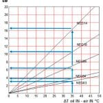
In a true balance, what goes in must be accounted for, either as a temperature increase or transfer of heat out of the system. Thus, if generated heat is higher than that dissipated, a heat exchanger with a cooling capacity of that difference is selected. When designing a new hydraulic elevator system, a good rule of thumb is that a cooler should be sized to remove approximately 25-30% of the input power. Cooler manufacturers have selection charts that make the selection of coolers relatively easy. The size of the cooler is based on the amount of heat (in kilowatts) that needs to be neutralized with respect to a temperature difference (△T) in accordance with ambient temperature. Figure 7 shows a typical selection chart of oil cooler sizes from a cooler manufacturer.
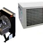
An oil cooler (heat exchanger) typically operates with the help of a thermostat switching the cooling circuit on and off. The operating temperature of the thermostat contact can be set from outside by means of a hand wheel. The sensor element is immersed into the oil. The thermostat of the oil cooler should be adjusted so it comes into operation after a 10-12°C increase from the ambient temperature. A pump is used to deliver hot oil from the tank to a heat exchanger. Oil is cooled there by a motor-driven fan – a process similar to the water-cooling system in an automobile. The cooled oil is then pumped back into the tank for use by the elevator system. The exchanger is installed on the wall of the machine room such that it blows warm air out. The calories (amount of heat transfer) depend on the size of the cooler.
Refrigerated oil coolers are uncommon but can also be found in installations where the ambient temperature is very high and the elevator is used frequently, such as in shopping malls, hospitals, exhibition centers, etc. A refrigerated oil cooler works very much on the same principle as a refrigerator. The warm oil from the tank, which is circulated by means of a pump, exchanges its heat with the coolant, being circulated in the refrigerator by a compressor. Thus, the oil is quickly cooled and delivered back to the hydraulic tank.
Learning-Reinforcement Questions
Use the below learning-reinforcement questions to study for the Continuing Education Assessment Exam available online at www.elevatorbooks.com or on p. 173 of this issue. Which critical design aspects can influence heat generation and dissipation in a hydraulic elevator?
♦ How is heat load analyzed?
♦ How can component selection and adjustment affect heat generation?
♦ How are heat dissipation and heat generation calculated?
♦ How should the cooler size be calculated (if needed) once the heat load has been ascertained?
- Figure 1: Schematic of a hydraulic power unit
- Figure 2: MRL hydraulic elevator system
- Figure 3: Oil viscosity grade table
- Figure 4: Valve adjusted for longer leveling time
- Figure 5: Valve adjusted to correct leveling time
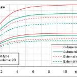
- Figure 6: Effects of motor and valve types on thermal balance temperature: Z: starts per hour; MV: mechanical valve; EV: electronic valve[1]
- Figure 7: Thermal exchange diagram; courtesy of Seim S.r.l. (Italy)
- Figure 8: Cooler types; courtesy of Seim S.r.l.
- Table 1: Typical travel times for mechanical and electronic valves: 1 depends on the temperature and pressure ranges; 2 depends on the travel speed.
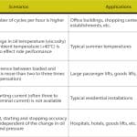
- Table 2: Advantages and applications of VVVF systems
Reference
[1] K. Ferhat Celik and Murad Kucur. “Importance of Thermal Balance for Hydraulic Elevators,” Elevator Technology 18: Proceedings of Elevcon 2010.
Get more of Elevator World. Sign up for our free e-newsletter.
