Manual Release of Brakes in MRLs and Its Challenges
Aug 1, 2023

A critical safety task
by Lakshmanan Raja
Value: 1 contact hour (0.1 CEU)
This article is approved for Continuing Education by NAEC for CET® and CAT®.
EW Continuing Education is currently approved in the following states: AL, AR CO, FL, GA, IL, IN, KY, MD, MO, MS, MT, NJ, OK, PA, UT, VA, VT, WA, WI and WV | Canadian Province of BC & ON. Please check for specific course verification of approval at Elevator Books.
Learning Objectives
After reading this article, you should have learned about:
- Manual release of brakes for emergency rescue operations of an elevator with a machine room and without (machine-room-less [MRL])
- Code requirements related to manual release of brakes and rescue operations in MRL elevators
- Mechanical means for releasing the brake with levers, brake-release cable and its challenges due to the capstan effect
- Electrical means for releasing the brake using a battery, and with automatic speed control feature
- Comparison between mechanical and electrical means and ways of overcoming the challenges
The manual release of brakes is considered the most safety-critical task because during the normal operation of elevators, brakes are energized to open only after ensuring that the safety circuits* and door circuits# are closed and the motor is powered. Hence, by releasing the brake directly, we are overriding many safety controls and assuming a huge responsibility. It should be the last resort executed by elevator personnel during emergency rescue situations. Emergency situations arise when passengers are trapped in an elevator due to power failure, as there is no backup power in the building or it is not working. Passengers may also get trapped due to control failures like drive failure, motor failure or other motion control failure, which take longer to troubleshoot and repair. In such situations, rescuing passengers by manually releasing the brake is the only option. Manually releasing the brake is also needed for testing purposes. As this brake release operation involves high risk, the features used to perform this task should be well designed, installed and maintained. Unfortunately, these manual brake-releasing devices are not used often, and they are usually overlooked. This article sheds some light on those devices and their features and highlights the challenges to be considered.
There are some exceptions.
#Per A17.1, 2016-2.12.3.1. Door circuit may get bypassed by other control circuit. Examples: Car leveling or truck zoning device (2.26.1.6), hoistway access switch (2.12.7), by the use of hoistway/car door bypass switches (2.16.1.5) or during the advance door opening feature.
*Per A17.1, 2016-2.7.6.5.2 (h) — landing inspection operation switch shall bypass the following: car safety mechanism switch, car buffer switch, final terminal stopping and car and counterweight governor switches.
Elevators With Machine Rooms
For elevators with motor machine rooms, elevator personnel are able to stand within proximity of the traction machine, manually release the brake using the brake releasing tool provided, observe the car speed and control car movement during rescue and test operations. Due to the imbalance between the car and counterweight, the release of the brake will cause the car to accelerate either upward or downward. An authorized elevator mechanic must repeatedly release and apply the brake to control the movement of the car and to stop it within the unlocking zone.
Industry practice in the field is to mark the suspension rope to identify the floor level. The person performing the rescue operation will stop the car approximately at the floor level by observing that marking. After that, he can go down to the respective floor to open the elevator door for the trapped passenger to safely exit the elevator car.
Therefore, the person opening the brake must be very observant and skillful to open and close the brake at the correct interval. If the brake is held open for a longer time, the car will reach a dangerous speed@, which can cause serious injury to the person inside the car due to the car’s sudden stop when the brake is applied again.
@This can be avoided in the traction machine, which uses a permanent magnet synchronous machine (PMSM) with the dynamic braking feature.
MRL Elevator
The introduction of the MRL elevator in 1996, and the inclusion of such arrangements in the ASME A17.1S-2005 supplement edition, brought advantages and challenges. The important challenge in the MRL is that the traction machine is located inside the hoistway: It is difficult to observe the machine closely for car speed, direction, approximate speed and the arrival of car into the door-unlocking zone while performing the rescue operation. Therefore, the code included all those requirements for an MRL.
Code Requirements
I have listed the A17.1-2016 rules related to MRLs, especially on the manual break release and rescue operations (with my interpretation) in Table 1. For accurate information, readers should refer to the A17.1 code book and the relevant handbook.
| Rules | Interpretation by Author |
| 2.7.6.2 | Allows the machinery spaces and control spaces to be located inside or outside the hoistway. |
| 2.7.6.3.1 | Allows the electric driving machine to be located in machinery space or machine room. |
| 2.7.6.4 | Since the machine and brakes are allowed to be located inside the hoistway, rule 2.7.6.4 and rule 2.7.6.4.1 through 2.7.6.4.3 dictate the requirement for means necessary to conduct the test, which requires the movement of the car and the releasing of the brakes to be provided outside the hoistway. It also permits elevator personnel to use those means for passenger rescue. |
| 2.7.6.4.1 | While elevator personnel conduct the necessary tests or rescue from the location outside the hoistway, where direct observation of the elevator drive sheave or ropes is not possible, rule 2.7.6.4.1 requires display devices or the equivalent shall be provided to convey information like the direction of movement of the elevator car, speed of the elevator car and the arrival of the elevator car into the unlocking zone. Those display devices shall function for at least 4 h when normal power fails. If batteries are used for that purpose, then their power should be monitored. The car shall not be allowed to restart after a normal stop at the landing if the battery power is insufficient. |
| 2.7.6.4.2 | Allows the means necessary for tests to be located within an inspection and test panel conforming to the requirements in 2.7.6.5.2. to prevent unauthorized access. As per 2.7.6.5.2, inspection and test panels are to be kept closed and locked. The key shall be Group 1 security, which covers access or operation of equipment restricted to elevator personnel. Inspection and test panels shall include display devices as required by 2.7.6.4.1. |
| 2.7.6.4.3 | Means to move the car from outside the hoistway shall conform to the following: It shall not be dependent on the availability of normal power and shall be accessible by elevator personnel only. It shall allow the car to move only with continuous effort. If the car is moved manually, the effort required to move the car in the direction of load imbalance shall not exceed 400 N (90 lbf). If the means used is removable, it shall be stored outside the hoistway and access to the means shall be with a key that is Group 1 Security. It shall be suitably marked to indicate the machine for which it is intended. Where the manual effort required to move the car exceeds 400 N (90 lbf), a means of electrical operation shall be provided to allow the car to be moved. This means of electrical operation shall require constant pressure on operating devices to move the car, and when activated, operation of the car by all other operating means shall be prevented. Failure of a single constant pressure operating device shall not permit the elevator to move or continue to move. Where batteries are used for this electrical operation, a monitoring system shall be provided. In the event that — during normal operation of the car — the monitoring system indicates insufficient power to move the car, the car shall not be permitted to restart after a normal stop at a landing. |
| 2.24.8.4 | Manual release of the driving machine brake is permitted. However, the car movement should be in a gradual, controllable manner. The manual release device shall be designed to be hand applied only with continuous effort. Provisions are made to prevent the unintended actuation of these devices. The brake shall reapply at its fully adjusted capacity in the absence of the hand-applied effort. When the manual-release device is in use, ascending car overspeed protection or an unintended car movement protection device is permitted to be temporarily disabled. |
| 2.26.8.1 | Driving-machine brakes shall not be electrically released until power has been applied to the driving-machine motor, except as permitted by 2.7.6.4.3. |
Table 1: Code interpretation
Most of the manual brake-releasing arrangements used in the elevator industry are based on either mechanical or electrical technology. Both have advantages and challenges.
Mechanical Means
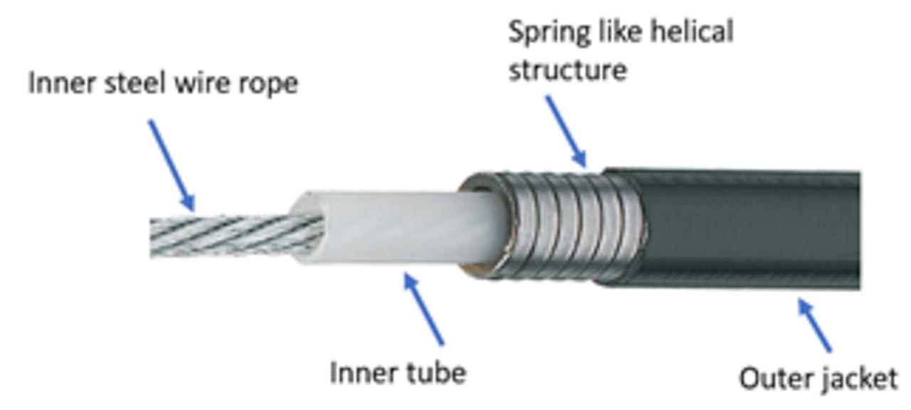
This kind of manual brake-releasing arrangement includes a pivoted lever placed at the inspection and test panel, connected by a brake release cable (Bowden cable) to the drive machine brake, located inside the hoistway. The release cable consists of thin multi-stranded steel-wire rope routed through a flexible conduit like housing, which is similar to the one seen in a bicycle for releasing the brake. The housing consists of an inner lining/tubing to reduce friction, a non-compressible layer of steel wire wound in a helical structure like a spring and a protective outer jacket covering as shown in Figure 1.
Apart from that, there will be display devices to indicate car moving direction, speed and the presence of the car in the door unlocking zone. These display devices are required to function for at least 4 h when the normal power fails. This is needed for rescue operations during a power failure. If batteries are used for that purpose, then their power is to be monitored and the car shall not be allowed to restart after a normal stop at the landing if the battery power is found to be insufficient.
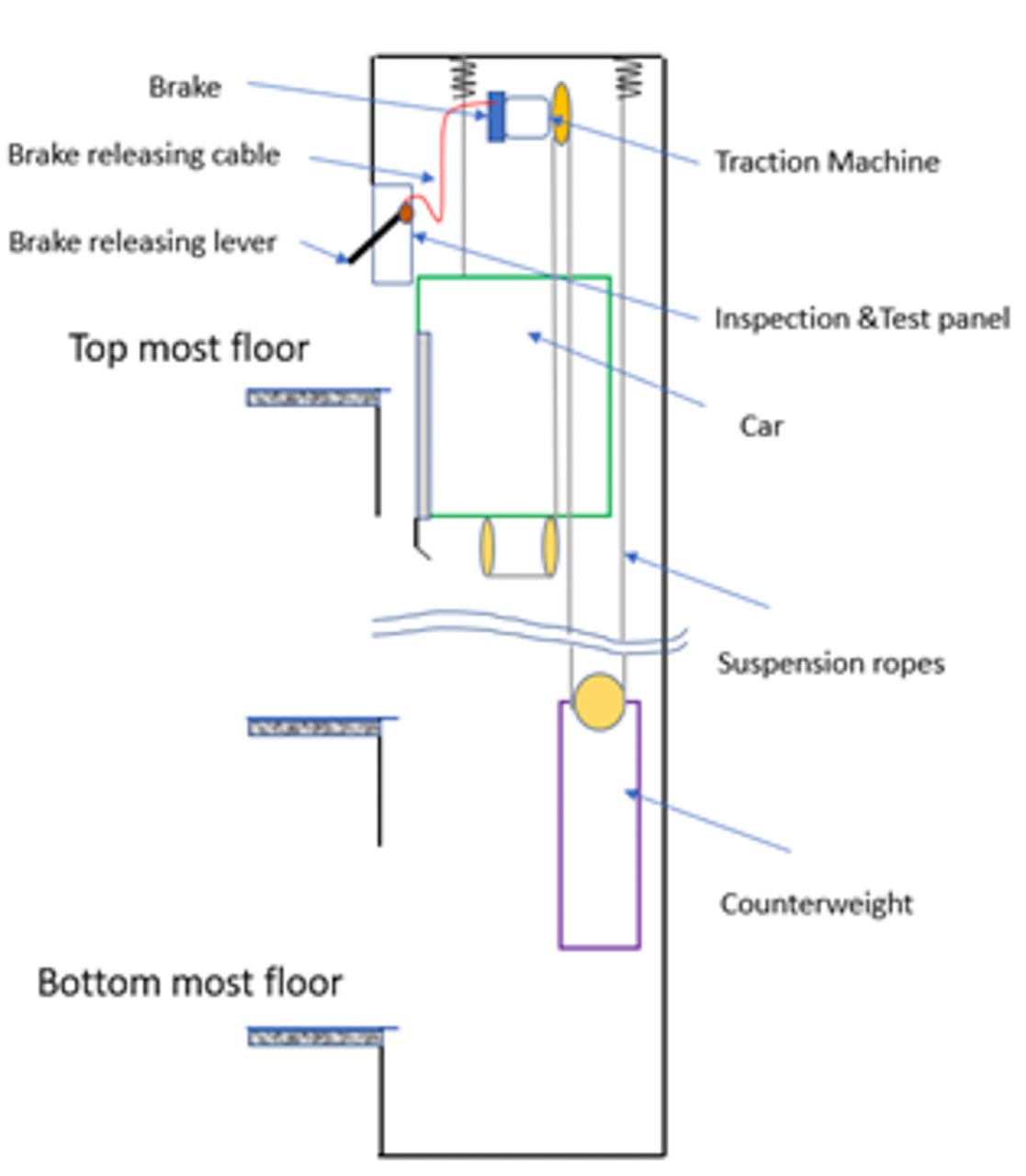
During the rescue operation, when the lever is moved from outside the hoistway, the inner wire rope of the cable slides over the tubing of the conduit and pulls the brake releaser located at the traction machine and, thus, opens the brake. That is how mechanical energy is transmitted through the flexible path. However, the flexibility doesn’t come friction-free, and there is friction, which depends on how the cable is laid. A similar MRL arrangement with mechanical means for releasing the brake is shown in Figure 2.
If the cable is laid with many bends, then its energy transmission efficiency reduces. It is governed by the capstan equation: eμθ=Ratio between the tension forces on the cable before and after the bend
Where µ is the friction coefficient and θ is the angle in radian subtended by the bend. If there are multiple bends, then their angles are added. Figure 3 and the subsequent analysis show how this relationship is derived.
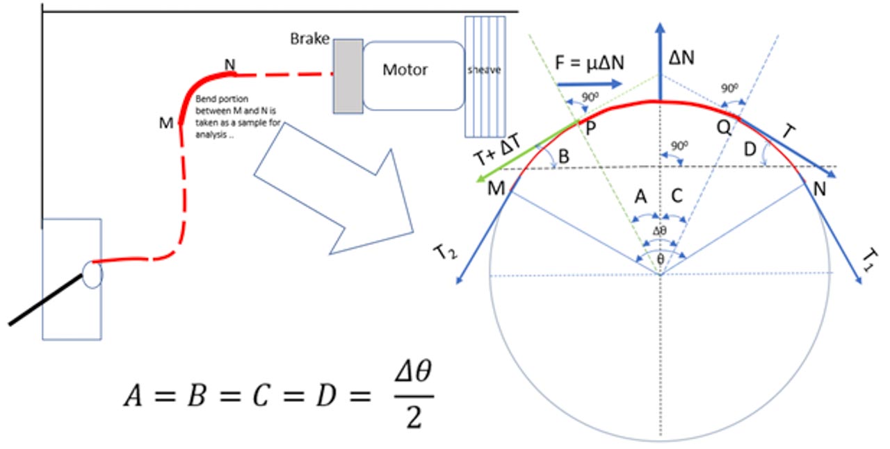
Considering the situation in which the brake is manually opened by moving the lever at the inspection and test panel, it creates a pull force on the rope inside the brake-release cable, and it is just about to move toward the left. The bend portion (arc MN) of the cable is taken for our analysis to study. Let:
- T2 be the tension at the lever side
- T1 be the tension at the brake side
- θ be the angle subtended by the arc MN
Now consider a small segment PQ within the arc MN of the bend portion, which subtends an angle Δθ at equilibrium condition and let:
- T + ΔT be the tension at the lever side
- T be the tension at the brake side
- ΔN is the normal force acting on this small segment
- µΔN be the friction force and
- As the segment PQ subtends an angle Δθ, and it is equally divided between ∠A and ∠C: ∠A=∠C= Δθ/2
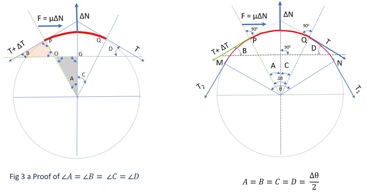
- Consider the two triangles OPB and OGA in Figure 3A.
- ∠G=90°
- ∠P=90° since P is at the meeting point of a tangent with radius.
- ∠O is of same value in both triangles as it is an opposite angle.
- Two angles in both triangles are of the same value. Hence, the third angle ∠B= ∠A.
- In the same way ∠C= ∠D.
- Thus ∠A=∠B= ∠C=∠D= Δθ/2
Now resolving the force horizontally and summing to zero since the rope is just about to move and the system is in equilibrium.
In the same way, resolving the forces vertically and summing to zero:
Now substituting the value of ΔN, which we found from equation 2 into the equation 1:
Dividing all the terms with Δθ:
Dividing the numerator and denominator of the second term by numeral 2:
Rearranging the second term, we get:
If we now let Δθ approach zero, then:
It will result in a following differential equation:
We got the relationship as dT/T=µdθ for the considered small segment PQ of the cable.
To evaluate the full bend portion MN, we integrate the left-hand side of the equation with tension from T1 to T2 and the right-hand side from angle 0 to θ.
After integration, we obtain:
By taking the exponential on both sides, we have:
The ratio of the tension force increases exponentially with the coefficient of friction and the cumulative angle subtended by the bends in the brake release cable.
Note: The equation derived is the Euler-Eytelwein equation, which is nothing but the traction equation. In the traction application, we enhance the friction coefficient µ by using a different groove profile on the drive sheave and the holding force by the increasing of the wrap angle θ. However, in the brake-releasing application, we need less friction coefficient and the wrap angle (angle subtended by turns), which is opposite to that of traction application.
From Equation 3, we understand that whenever there is a bend in the brake-releasing cable, the applied input force is reduced by the factor eμθ.
- µ is the friction coefficient, which depends on the materials used for manufacturing the cable.
- θ is the cumulative angle in radian, subtended by the turns. This angle has to be controlled during installation in the field.
Cumulative bend angle | Friction Coefficients | ||||
0.2 | 0.3 | 0.4 | 0.5 | 0.6 | |
0.5π | 0.7304022 | 0.6242277 | 0.5334873 | 0.4559373 | 0.3896603 |
π – half turn | 0.5334873 | 0.3896603 | 0.2846087 | 0.2078788 | 0.1518351 |
1.5π | 0.3896603 | 0.2432368 | 0.1518351 | 0.0947797 | 0.0591641 |
2π – single turn | 0.2846087 | 0.1518351 | 0.0810021 | 0.0432136 | 0.0230539 |
2.5π | 0.2078788 | 0.0947797 | 0.0432136 | 0.0197027 | 0.0089832 |
3π | 0.1518351 | 0.0591641 | 0.0230539 | 0.0089832 | 0.0035004 |
3.5π | 0.1109007 | 0.0369319 | 0.012299 | 0.0040958 | 0.001364 |
4π – two turns | 0.0810021 | 0.0230539 | 0.0065613 | 0.0018674 | 0.0005315 |
4.5π | 0.0591641 | 0.0143909 | 0.0035004 | 0.0008514 | 0.0002071 |
5π | 0.0432136 | 0.0089832 | 0.0018674 | 0.0003882 | 8.07E-05 |
5.5π | 0.0315633 | 0.0056076 | 0.0009962 | 0.000177 | 3.144E-05 |
6π – three turns | 0.0230539 | 0.0035004 | 0.0005315 | 8.07E-05 | 1.225E-05 |
| Efficiency value reduces as the cumulative bend angle and friction coefficient increases | ||||
Table 2: Efficiency of brake-release cable for various µ and θ
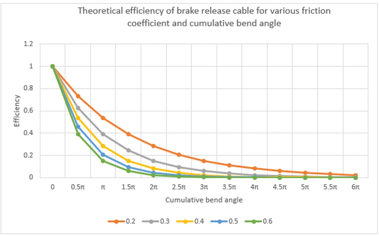
The theoretical efficiency of the brake-release cable for various friction coefficient and cumulative bend angles is plotted in the graph shown in Figure 4 and the corresponding datapoints are given in Table 2. We can see from the graph that the brake cable efficiency reduces with the increase in the friction coefficient and the cumulative bend angles.
During manual brake release, force is applied by elevator personnel at the lever side. This moves the inner wire rope of the brake release cable toward the lever and opens the brake. Once that force is withdrawn, then the brake will start to close, and while closing, it will pull back the inner wire rope toward the brake side. The capstan effect applies to both situations, thus preventing the movement of the inner wire rope. The following example illustrates this clearly.
Example: Considering Figure 5, the brake cable used is with friction coefficient 0.2. The releasing force required by the brake is 200 N.
Case 1
The cumulative angle subtended by the brake release cable observed from Figure 5 is calculated as π/2+ π/2+2π=3π.
The force to be applied by elevator personnel at the lever located outside the hoistway for opening the brake is = 200 N X e0.2×3π = 1317 N. (Note: A lengthy lever/extension bar can be used to reduce this force. The mechanical advantage of such items is not considered here.)
Case 2
The cumulative angle subtended by the brake release cable observed from Figure 5 is calculated as π/2+π/2=π.
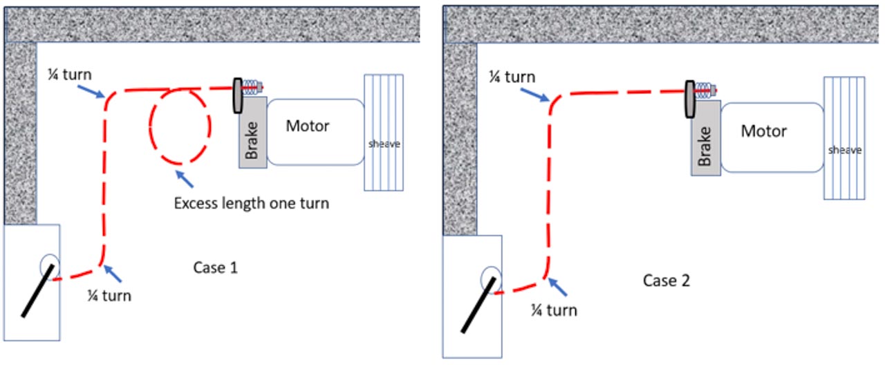
The force to be applied by elevator personnel at the brake-releasing lever located outside the hoistway is = 200 N X e0.2×π = 374 N.
The example clearly shows the importance of proper laying of brake release cable. The cumulative bend angle must be reduced as much as possible. With a just addition of one full turn in Case 1, the force required to open the brake increased by four times, and that is the effect of the factor eμθ.
Now consider a situation in which the elevator personnel withdraws his effort, and the brake starts to close. The brake exerts a pull force of 200 N on the inner wire rope, and the inner wire rope starts to move towards the brake side. Assuming the brake release lever or the end termination of the inner wire rope has some frictional/loading issues and it exerts some residual holding force. Let us calculate how much residual force present at the lever side may stop the brake from closing and compromise the brake’s effectiveness. Let that residual force be Fresidual.
For Case 1, a small force of 30 N is able to prevent the movement of the inner wire rope and, thus, prevent the brake from completely closing back. If the residual force present at the lever side is 15 N, then it can partially compromise the brake operation. For Case 2, since it is with less bends, it requires 107 N to compromise the brake operation completely. Case 2 has higher immunity since the cable is laid with lesser bends.
The Bowden cable inner wire rope movement on both directions is restricted by the capstan effect. This is not allowed by the code, as the code has a requirement that states that the brake shall reapply at its fully adjusted capacity in the absence of the hand-applied effort (A17.1 2016 – 2.24.8.4). The manufacturer might have added extra springs to ensure the proper retracting of the inner wire rope after the brake release operation. Downstream contractors should understand the importance of such springs so there won’t be any negligence during installation and maintenance.
In addition, manufacturer installation procedure should clearly state the maximum cumulative bend angle allowed and the minimum bend radius to be maintained. Although the cable bend radius is not a part of Equation 3, small bend radius increases the wear on the cable, which negatively influences the friction coefficient over time. The bend radius recommended by the manufacturer is at least 20 times greater than or equal to the inner wire rope diameter. After installation, with the necessary precaution, the field professional tests and ensures that the usage of the manual release device is free from any resistance and doesn’t compromise the brake operation.
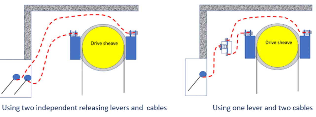
So far, we have done our study on one brake opened by one lever. If there are two brake units on the machine, then examples of arrangements to open the brake individually are shown in Figure 6. However, a similar kind of force analysis and capstan effect applies to such arrangements.
Electrical Means
In this rescue system, electrical energy is used to release the brake. Electrical energy is obtained from a battery. This battery is charged from normal power through the charging circuit. The charge of the battery is to be monitored, and if the charge is below the threshold, the car shall not be permitted to restart after a normal stop at a landing. Electrical energy to the brake is controlled by constant pressure operating devices, which are operated by the elevator personnel for moving the car. The failure of a single constant pressure operating device shall not permit the elevator to move or continue to move.
Most of the electrical rescue systems have more functions than just opening the brake. They have a speed monitoring and control feature that will cut off the brake power when the elevator speed exceeds certain preset limits and resets after some predetermined time. This is similar to elevator personnel controlling the car movement by repeatedly opening and closing the brake in the mechanical rescue system. However, here it is done in an automated way.
Setting up a speed limit below the inspection operation speed is a safe industry practice because the trapped passenger will experience the sudden stop from that speed when the brake is switched OFF. A17.1 2016 – 2.26.1.4.1 states the inspection speed limit as less than 0.75 ms/s. Speed governor overspeed contacts can be used as an input for overspeed detection circuit as additional safety layers. Apart from that, there are indicators to show whether the elevator car reached the door zone, car moving direction and approximate speed.
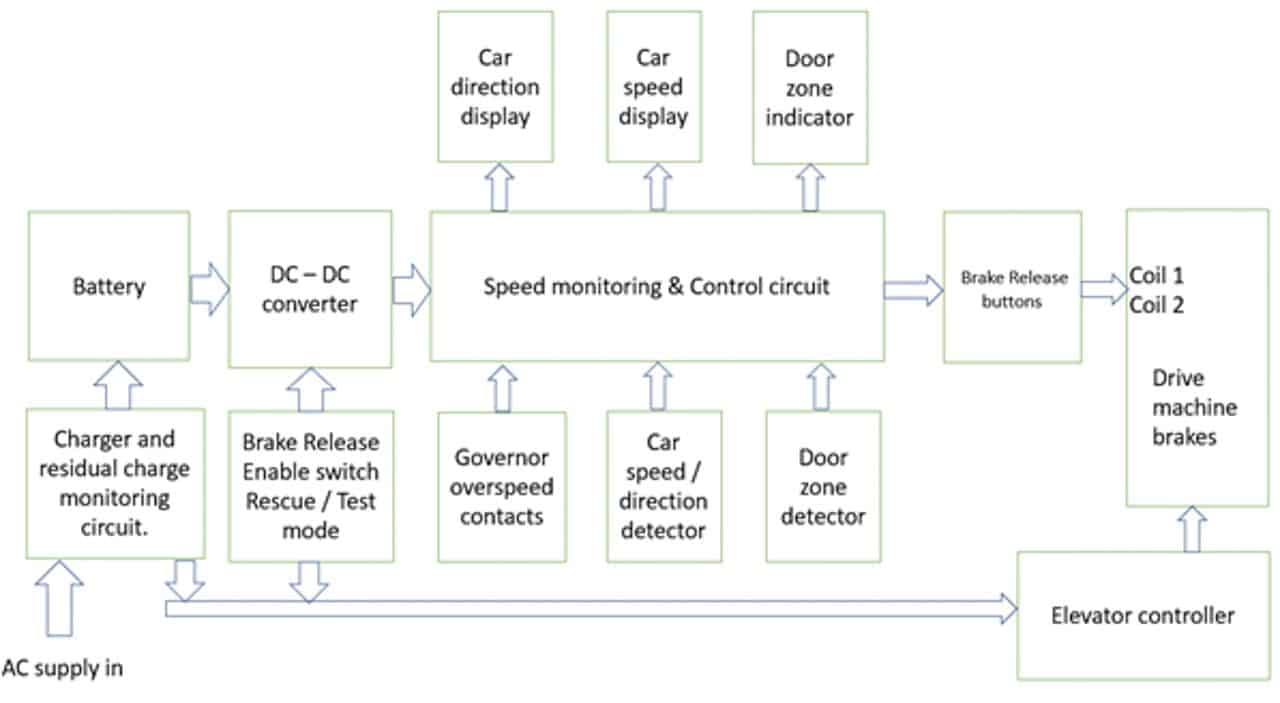
A typical arrangement of such systems is shown in Figure 7. During the rescue operation, elevator personnel have to change the enable switch to rescue mode. This will enable the DC-DC converter, which converts the battery voltage to the voltage required by the brake coil. As the elevator is still stationary, the speed monitoring circuit will allow this voltage to reach the brake-release buttons. There may be two release buttons if there are two coils for the brake. Both have to be pressed continuously for the current to reach both coils and energize it to open the brake. Due to the imbalance in the load between car and counterweight, the car will accelerate either up or down. When the speed reaches the set limit, the speed-monitoring circuit cuts off the supply to the brake coil and the elevator stops. If the buttons are kept pressed continuously after the car is stopped, the speed-monitoring circuit will allow the supply to reach the brake coil after a predefined time, which can be seen from the graph in Figure 8. The brake is energized to open now, the car starts to accelerate and this cycle repeats a few times until the car reaches the door zone.
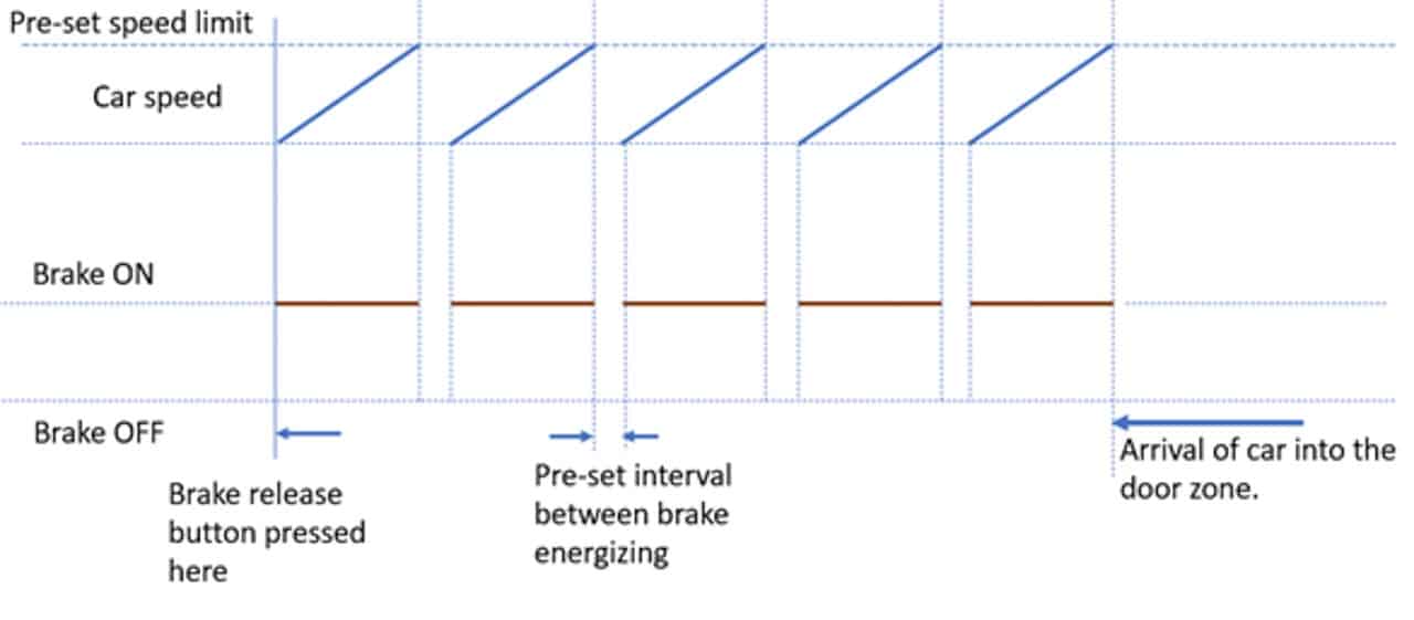
Response of the ON-OFF controller for controlling the car speed is shown in Figure 8. The increase in speed after opening the brake may not be linear as shown in the graph, and it won’t become zero immediately after the brake is de-energized. The graph is a very simplified conceptual view of the ON-OFF controller.
Conclusion
Time and safety are important factors while performing rescue operations. The reliability of systems used for the manual release of brakes is critical. Manual release systems are not used in everyday, normal operation of the elevator, and their failure will not be easily noticed. Inspection and testing of such items are very important. I have summarized the key differences and common requirements between the mechanical and electrical manual release system in Table 3.
| Mechanical Means | Electrical Means | |
| 1 | Manual brake release is done by mechanical energy transmitted from a brake-releasing lever located outside the hoistway through a Bowden cable to the brake releaser of the traction machine inside the hoistway. | Manual brake release is done by electrical energy transmitted by electrical wires from a chargeable battery to the brake coil inside the hoistway. Batteries have to be monitored during normal operation of the elevator, and if the charge is insufficient, then the car shall not be permitted to restart after a normal stop at a landing. |
| 2 | Control of car speed during rescue operation depends on the elevator personnel’s skill. If he is not skillful enough and kept the brake continuously open for a long time, the car may accelerate to a high speed, and stopping after that may injure the trapped passenger. However, this is avoided when using a PMSM with dynamic braking features. | Automatic overspeed prevention can be incorporated into the system, thus preventing the possibility of the car reaching a high speed and coming to a sudden stop. Speed governor overspeed contacts can be used as an input for overspeed detection as an additional safety layer. Thus, overspeeding of the car due to human error can be avoided. |
| 3 | Friction of the brake-release cable plays a significant role. The cable is to be laid in such a way to reduce the angle it subtends. Sharp bends are to be avoided. Manufacturer installation manuals must provide those details and field professionals should adhere to them. | Reliability of printed circuit boards and the electronic components used plays a significant role. Since these components are controlling the opening of the brake directly, their failure modes have to be studied and taken care of. |
| 4 | Both means shall be designed to be hand applied only with continuous effort. Provisions are made to prevent the unintended actuation of these devices. The brake shall reapply at its fully adjusted capacity in the absence of the hand-applied effort. | |
| 5 | Both means to be provided with display devices or the equivalent to convey information like the direction of elevator car movement, its speed and the arrival of the elevator car into the unlocking zone. Those display devices shall function for at least 4 h when the normal power fails. If batteries are used for that purpose, then their power is to be monitored. The car shall not be allowed to restart after a normal stop at the landing if the battery power is insufficient. | |
Table 3: Comparison of mechanical and electrical rescue means
For more information, readers are advised to refer to the respective code, handbook and manufacturer installation and maintenance manuals.
“Zero Energy State”
submitted by Dave Smarte and Ray Downs
A mechanical energy source deals with the moving parts of any machine or system, and the electrical energy source focuses on the design and testing of the system to overcome any challenges in the safe operation of the product. When dealing with mechanical or electrical energy sources, the elevator technician must ensure they establish a “Zero Energy State” both mechanically and electrically. This can be done by following your company safety policy, and as a second option, review the 2020 Elevator Industry Field Employees’ Safety Handbook. Refer to Section #3 – 3.1 Proper Clothing; 3.2 Eye and Face Protection; and 3.7 Hand Protection, Also, review Section 7.1 Lockout and Tagout (Safety Absolute #4) and Section 7.1 Mechanical Stored Energy (Safety Absolute #5) for additional assistance.
Dave Smarte is Global Education and Safety officer at the National Association of Elevator Contractors. Ray Downs is senior VP, Environmental Health and Safety-TEI Group.
References
[1] Schiele, Andre, Pierre Letier, Richard Van Der Linde, and Frans Van Der Helm. “Bowden cable actuator for force-feedback exoskeletons.” In 2006 IEEE/RSJ International Conference on Intelligent Robots and Systems, pp. 3599-3604. IEEE, 2006.
[2] Jones, J., J. Burdess, and J. N. Fawcett. Basic mechanics with engineering applications. Routledge, 2012.
[3] Beer, Ferdinand P., E. Johnston Jr., Mazurek Russell, F. David and Elliot R. Eisenberg. “Vector Mechanics for Engineers: Statics (SI Units).” 7th edition, McGraw Hill Higher Education.
[4] ASME A17.1-2016, Safety Code for Elevators and Escalators, American Society of Mechanical Engineers.
[5] ASME A17.1S-2005, Supplement to ASME A17.1 – 2004, Safety Code for Elevators and Escalators, American Society of Mechanical Engineers.
[6] Otis Elevator Co. “Elevator Rescue System” U.S. Patent No. 6,196,355. March 6, 2001.
[7] Kone Oy “Arrangement for Releasing the Brake of an Elevator Machinery” U.S. Patent No 5,971,109. October 26, 1999.
[8] Installation and operational instruction for Mayr — ROBA — twinstop elevator brakes mayr.com/produkte/einbau-und-betriebsanleitungen/b.8012.en.pdf
Learning-Reinforcement Questions
Use the below learning-reinforcement questions to study for the Continuing Education Assessment Exam available online at Elevator Books or on p. 141 of this issue.
- What are the challenges in manually releasing the brake for doing a rescue operation in an MRL?
- What are the code requirements related to manual release of brake for performing a rescue operation in an MRL?
- How do the mechanical rescue means function in opening the brake from outside the hoistway using the brake release cable, and what challenges are involved?
- How do the electrical rescue means function with their automatic overspeed detection system, and what challenges are involved?
- How are the challenges of both rescue means handled?
Get more of Elevator World. Sign up for our free e-newsletter.
![]()


![]()