Model Lifts
Sep 1, 2021
A look at their fraught beginning and evolution into acceptance
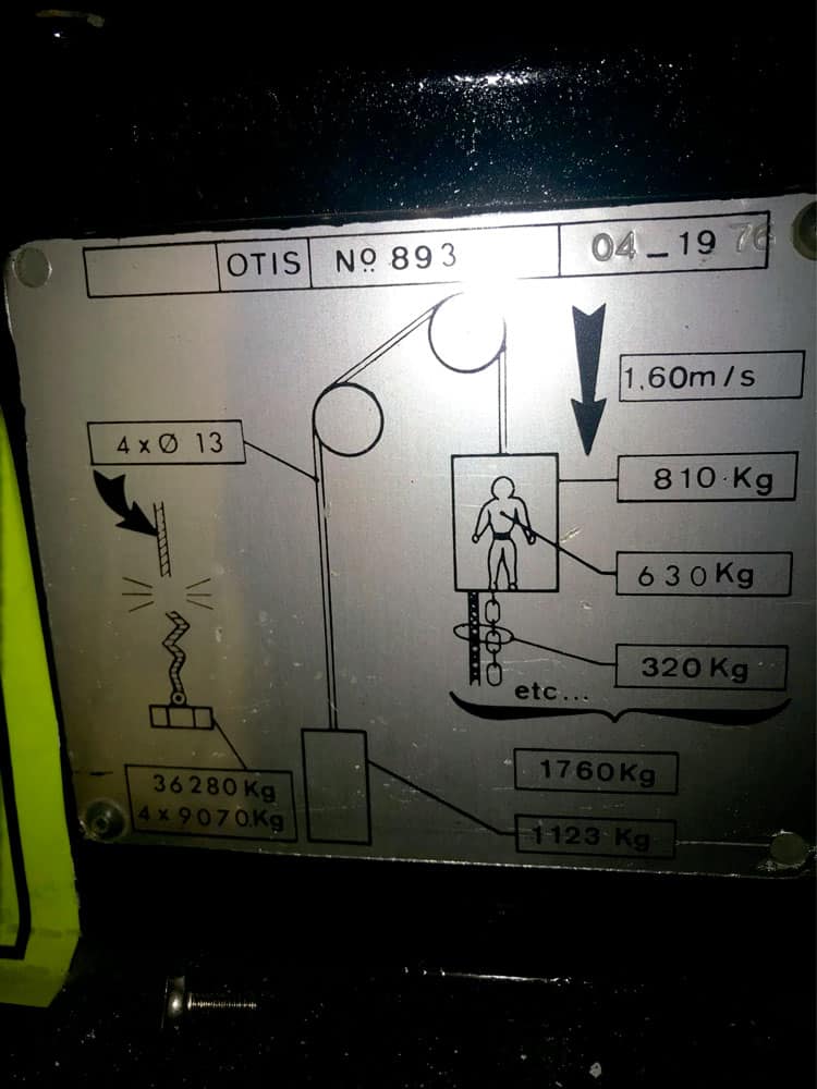
I found a recent LinkedIn post relating to the engineering and suspension rope provisions applied to a 1976 Otis LM893 passenger lift (Image 1) to be of interest. This lift design was one of several early developments of standardised or model lifts. They incorporated reduced car weights together with several other changes, which, when considered with the wider level of technological change extant at the time, is of interest.
I also came across a paper by Harry Pettinger, a respected Otis and industry leader whose experience extended from 1937 to 1982, and who had both observed and participated in the technological and commercial change that arose post WWII.
Pettinger presents several arguments in support of the model lift concept (formulated perhaps to ease concerns as much as to inform), drawing upon an analogy relating to standardisation in domestic white goods, and considering the production inefficiencies and higher costs inherent to traditional designs and the manufacture of custom equipment. Perhaps the most pressing aspect of the standardisation debate lay in new equipment lead times and the effect of these upon the construction sector. Traditionally, lead times had been in the region of 35 weeks or more from order. Pettinger also recognised efficiencies in field installation and in workforce understanding of the equipment, and envisaged that Otis’ output of model lifts would approach 50% of production in the “not too distant” future. He was certainly right in that respect, in that the current European market production of the major firms is predominantly based upon standard designs, perhaps up to 90% or more.
The introduction of CAD and CAM systems aided the drive to greater standardisation, as well as further reducing lead times as design and manufacturing time was reduced.
Issues of labour force deskilling, engineer earnings and job security arose, together with concerns as to customer acceptance (Traditionally, architects had design lifts meet their specific requirements).
In the late 1960s, Otis produced an early model lift range in the U.K. Whilst these were to a significant extent standardised, the quality and robustness of much of the equipment was far in excess of that applied today, and it is interesting to contrast the 1970s designs with some of today’s low-cost models.
In this case, the LM893 was designed for the EU market and of 630-kg capacity, equipped with four ropes of 13-mm diameter in a 1:1 configuration. The data plate indicates a car weight of 810 kg together with chain compensation and total attachments to the car at 320 kg. Excepting for the lift designation, the data plate is identical for all lifts of that capacity and reflects the worst case (highest rise) condition, reflective of another element of standardisation (Image 1).
This caught my interest in that I had worked on a two-stop LM891 (the single-speed equivalent of the LM893), which served only two stops (maybe a 3.5-m travel), but which was equipped with four 13-mm ropes and chain compensation. I had wondered at the application of compensation (together with a comparatively large machine and 13-mm diameter ropes) on a two-stop, single-speed lift, perhaps the lowest cost configuration of the standard range at that time. I found the inclusion of compensating chains, regardless as to rise and car speed, to be intriguing, and in low-rise applications, this was no more than a trade-off to standardisation in design and manufacture.
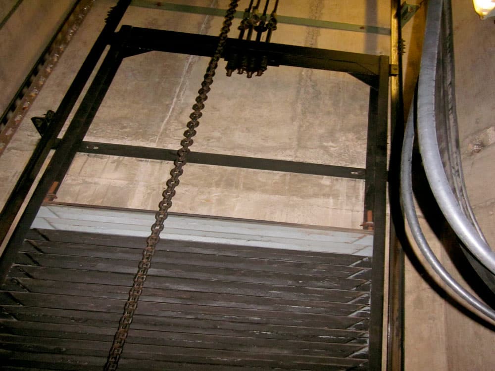
Guide rails were of reduced profile in comparison to those traditionally used, and a standardised (oversize) welded counterweight frame was applied (Image 2) that could readily accommodate the full load range from 320 kg to 1000 kg.
Overspeed governors on early models were of rope-grip design, which represented a significant additional cost in comparison to friction governors.
Preassembled wiring looms with modular plug-in terminal connectors, which included unfamiliar methods of terminal connection and circuit nomenclature, gave rise to some consternation.
Door system design followed the theme, with the application of simplified, lightweight operators and lightweight door panels replacing the heavier traditional designs. There were no detectors, just operator-mounted contact safety edges and, if you paid extra, a photocell or light ray in the car return.
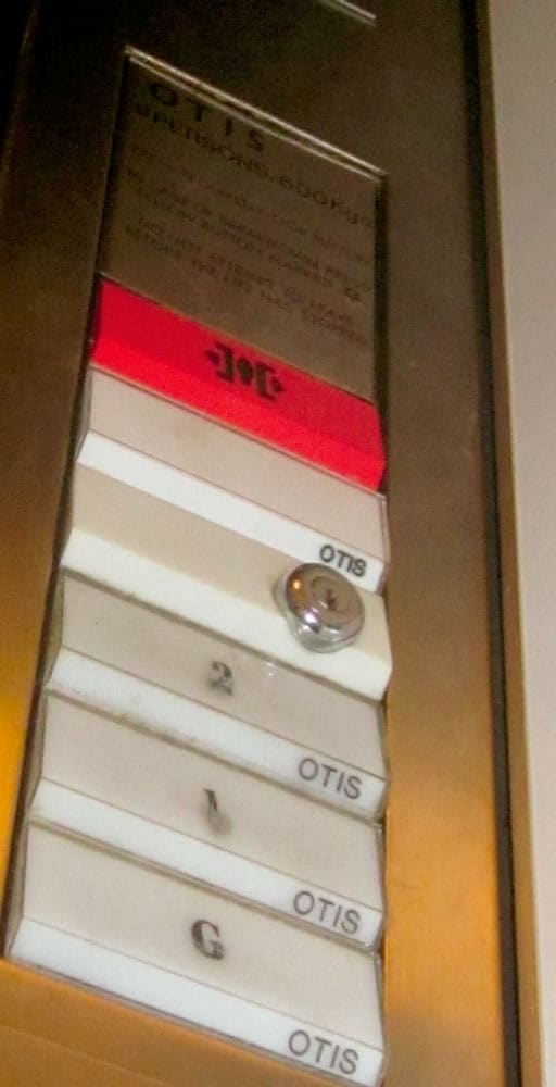
Fixture design followed a modernist theme with piano-key push button forms, bright colours and modular hall lanterns, together with early diode-based digital position indicator displays (Image 3). Faceplates, which had traditionally been formed in 3-mm-thick stainless steel, were produced in formed 1.5-mm stainless, which was far more readily pressed and cut to shape.
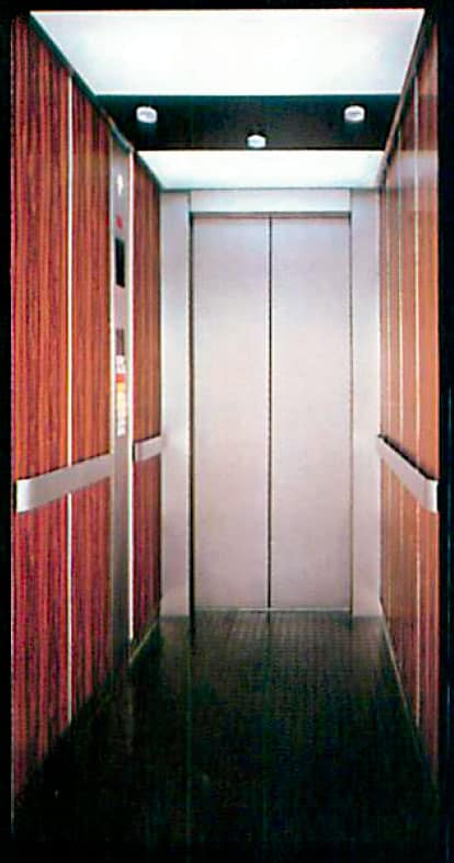
Car interiors came prepared for lining with a range of lightweight modular clip-in decorative liner panels. Door panels had detachable skins in stainless steel or paint finish (Image 4).
The reduced car weights did not result in an immediate reduction in machine size, as manufacturers continued with existing lines, although this did change during the 1980s when vertically configured motor/gear units became the preferred application.
Whilst aspects of the design practice of the time may now appear odd, it should be remembered this was a period during which the technology that underlies today’s equipment was developed, albeit there were too many instances of product development undertaken in the field, much to the annoyance of industry customers.
One problem that quickly became manifest was that of increased levels of noise and vibration, the level of which could vary between installations. These problems were investigated and eventually resolved in future car and system designs, such that today’s similarly lightweight cars do not generate the same problems.
One early model lift used a lightweight car in conjunction with a single-speed motor and geared machine with a large-diameter traction sheave. The resulting floor levelling accuracy was a constant source of complaint, and better designs incorporated a more realistic match between gearing and sheave diameter to provide better performance.
It may be argued that the U.K. Standard Housing design represented the first standardisation in lift design. However, this was imposed in response to cost efficiencies deemed to be necessary in support of the post-war housing construction boom, which continued from the 1950s into the 1980s, rather than having originated due to a purely market-driven influence. Standard Housing included some similar design principles, including the use of lightweight fluted-aluminium panelling in car construction, together with single-panel doors to reduce manufacturing and maintenance costs.
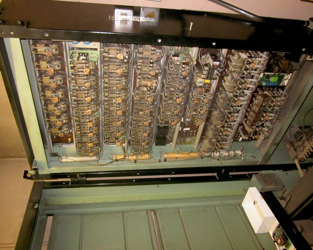
Whilst many in the industry were, and still are, critical of aspects of these model lift designs (an underlying element of a persuasive, and possibly even reluctant approach, is detectable in Pettinger’s paper), it is important to consider these in the wider context of the design thinking and technologies that prevailed and were emerging at the time. This was the transition period between electromechanical relay control and the microprocessor. Indeed, the LM893 was initially equipped with Ward-Leonard sets, relay controllers (Image 5) and floor selectors, evolving through to ACVV drives and various forms of electronic and early microprocessor-based controllers.
Overall, the surprising factor is that, despite the continued application of over-engineered and expensive components and associated increased costs, the product was cost-effective, even in low-rise applications.
Despite these clear inefficiencies (which would be designed out in later years), the benefits attained in the standardisation of design and manufacture were such as to render the overall system of production comparatively cost-effective relative to that of traditional design and manufacture. The problems that emerged from, and became apparent in, these early designs provided a fertile training ground for a budding young lift engineer, but they were not quite so well received by a number of industry customers.
Get more of Elevator World. Sign up for our free e-newsletter.


